Challenger Lifts, Inc - NY Tech Supply
Challenger Lifts, Inc - NY Tech Supply
Challenger Lifts, Inc - NY Tech Supply

You also want an ePaper? Increase the reach of your titles
YUMPU automatically turns print PDFs into web optimized ePapers that Google loves.
<strong>Challenger</strong> <strong>Lifts</strong>, <strong>Inc</strong>.<br />
Model’s 24012*<br />
*( E, W, EW, XL, LR, AR)<br />
FOUR POST SURFACE<br />
MOUNTED LIFT OPERATION, INSTALLATION &<br />
MAINTENANCE MANUAL<br />
IMPORTANT!!!<br />
READ THIS MANUAL COMPLETELY BEFORE INSTALLING OR OPERATING THE LIFT<br />
200 Cabel Street, P.O. Box3944<br />
Louisville, Kentucky 40201-3944<br />
Email - sales@challengerlifts.com<br />
Web Site -www.challengerlifts.com<br />
Office (502) 625-0700 Fax (502) 587-1933
Installation Procedure<br />
Models 24012 (E, W, EW, XL, LR, AR)<br />
Installation, Operation and Maintenance<br />
1. Determine the location for the lift installation. Fig. 1 gives the overall dimensions<br />
of the lift, including the drive on ramps. The area must be level and there must<br />
be free access to load and unload the vehicles.<br />
There must be enough overhead clearance to raise vehicles six feet above the<br />
floor. Thirteen feet is the recommended ceiling height.<br />
The floor must be 3000 psi concrete with a minimum thickness of four inches and<br />
steel reinforced per local commercial practice. If pads are used, they must be<br />
two feet square with a minimum thickness of twelve inches and steel reinforced<br />
per local commercial practice. Fig. 2 gives the pad layout dimensions.<br />
2. Refer to Fig. 3, General Arrangement. For muffler work, it is satisfactory to erect<br />
the lift with the cylinder beam on the left, or drivers side. For alignment and work,<br />
which require access to the front seat of the car, the top rail can be positioned on<br />
the right side so it is out of the way.<br />
3. Refer to Fig. 2 to get the dimensions for the post base locations. Refer to Fig. 1<br />
to determine where to locate the sides and ends of the post base plate with<br />
respect to walls and other obstacles at the installation. <strong>Inc</strong>lude additional<br />
clearance where required near walls and obstacles.<br />
4. Once the location is determined, use a chalk line to mark base line A-B to locate<br />
one side of the lift, refer to Fig 4. Use the width dimension from Fig 2 to measure<br />
off the dimensions A-D and B-C. Draw arcs as illustrated in Fig. 4. Draw a chalk<br />
line D-C tangent to the two arcs to establish the other side of the lift.<br />
5. Mark on one of the two parallel lines the points 1 and 2 to establish the ends of<br />
the post base plate as determined from Figs. 1 and 2. From points, 1 and 2<br />
measure diagonally to the opposite parallel line to determine points 3 and 4.<br />
Draw a chalk line between points 1 and 4 and points 2 and 3. The four lines<br />
locate the four outside corners of the post base plates.<br />
6. Position the cylinder beam and the two main side posts as shown in Fig. 5. The<br />
main side post which has the drilled hole pattern on one side is the power unit<br />
post. Bolt the cylinder beam to the main side posts using ½-13 x 1 3/4 bolts,<br />
washers, and nuts (use shipping bolts). Use 2 bolts on the power post and 3 on<br />
the other main side post.<br />
7. Lift the assembled cylinder beam to the upright position. Place the post base<br />
plate into their corners of the chalk line rectangle. Check the centering of the<br />
bolting slots of the top rail and main side leg tops. Correct as necessary, the<br />
main side post must be plumbed before tightening.<br />
8. Review the concrete anchor bolt instructions near the back of this manual. Drill,<br />
install, but do not tighten the 4 anchor bolts for the rear leg. DO ONLY THE<br />
REAR MAIN SIDE POST AT THIS TIME.<br />
File: 24107 2 Rev. 01.09.01
Models 24012 (E, W, EW, XL, LR, AR)<br />
Installation, Operation and Maintenance<br />
9. Plumb the post so that it is perpendicular. Use the level and check both side-toside<br />
and front to rear. Use shims, 3/4" steel flat washers or 1/16 or 1/8 thick by<br />
1" wide steel flat, strips are recommended for shims. Tighten the anchor bolts<br />
and recheck for plumb. Adjust if necessary.<br />
10. After anchoring the rear MAIN SIDE post, align the front post with the chalk lines.<br />
Check and adjust plumb of the front post. The base plate may vary from the<br />
measured dimensions slightly, but it is more important that the post be plumb and<br />
parallel with the other post. Install the anchor bolts in the front main side post.<br />
After completion of steps 8 & 9 tighten cylinder beam mounting bolts.<br />
IMPORTANT<br />
DO NOT DRILL OR SET OFF SIDE POST ANCHOR BOLTS AT THIS TIME.<br />
THE LIFT MUST BE CORRECTLY ALIGNED AND CYCLED BEFORE THE<br />
ANCHOR BOLTS ARE INSTALLED.<br />
11. Position cross rails in their approximate locations. Note: The tapped holes on<br />
the cross tube must be facing out for proper anti-sway installation. The<br />
lifting chain connector must be at the MAIN SIDE post location. See Fig. 6.<br />
12. Use a pull wire to pull the cross rail chain through the cross rail tube. The chain<br />
runs over the sheave at the main side end and under the sheave at the off side<br />
end. See Fig. 7. Repeat for the other cross rail.<br />
13. Attach the cross rail chain to the main side post chain anchor with a 5/16 headed<br />
pin and cotter key. Repeat for the other cross rail. See Fig. 6.<br />
IMPORTANT<br />
THE CROSS RAIL CHAIN MUST HAVE THE CENTER LINK AND IT MUST<br />
BE IN A VERTICAL POSITION, NOT COCKED TO THE FRONT OF THE<br />
CHAIN ANCHOR. FAILURE TO FOLLOW THIS REQUIREMENT COULD<br />
RESULT IN PERSONAL INJURY OR PROPERTY DAMAGE.<br />
14. Position a 2 x 4 block under the safety latch on the main side end of the cross rail<br />
as shown in Fig. 6. Remove the packing pin from the cross rail end assembly.<br />
Install a 3/4 nut onto the safety rod. Turn down the nut to the bottom of the<br />
thread on the rod. Insert the safety rod into the space previously occupied by the<br />
packing pin in the cross rail end assembly. Insert the threaded end of the rod<br />
into the rear hole at the top of the main side post. Secure the top of the safety<br />
rod with a 3/4 nut. The top 3/4 nut should be flush with the end of the safety rod<br />
and the bottom nut should be tightened against the post top cap. Remove the<br />
wooden block. Repeat at each post.<br />
15. Remove the cap from the front cylinder port. Manually extend the cylinder ram.<br />
Attach the lifting chains to each cross rail chain connector using a 5/16 x 3 grade<br />
8 shoulder bolt and lock nut. See Fig. 6.<br />
IMPORTANT<br />
THIS BOLT MUST BE THE SHOULDER BOLT SUPPLIED WITH THE LIFT<br />
OR MEET THE SPECIFICATIONS ABOVE. FAILURE TO FOLLOW THIS<br />
File: 24107 3 Rev. 01.09.01
Models 24012 (E, W, EW, XL, LR, AR)<br />
Installation, Operation and Maintenance<br />
REQUIREMENT COULD RESULT IN PERSONAL INJURY OR PROPERTY<br />
DAMAGE.<br />
16. Install the bolt end of the cross rail chain into the hole at the top of the off side<br />
posts. Attach the 1" washer and nylon lock nut to the bolt. Hold the chain with a<br />
crescent wrench and tighten the nut to remove most of the slack from the chain.<br />
Repeat for the other cross rail.<br />
17. Attach the power unit to the front main side post using the 5/16" hardware<br />
provided.<br />
18. Attach the hydraulic hose between the fitting at the rod end of the cylinder and<br />
the fitting just above the power unit tank. Secure the hose to the cylinder with<br />
the tie wraps.<br />
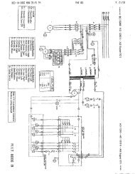
19. Connect the power unit to a dedicated 30 amp electrical branch circuit, using<br />
wiring methods prescribed by local codes. Refer to Fig. 8 for wiring schematic.<br />
20. Using a funnel in the breather cap fitting on the power unit reservoir, fill the<br />
reservoir with 11 quarts of clean petroleum or vegetable based hydraulic oil.<br />
DO NOT OVERFILL THE RESERVOIR. The oil level should be no higher than 2<br />
inches below the mounting flange of the tank. Check by removing the screw just<br />
below the reservoir cap, and filling until oil comes out of the hole. Replace the<br />
screw.<br />
21. Using the power unit, raise the cross rails about 6 inches. Level the cross rails<br />
by adjusting the cross rail chain tension at the top of the off side posts. Use a<br />
level to check the cross rails.<br />
22. Position the runways on the cross rails. Place the runways equal distance from<br />
the center of the cross rails. 36 ½" Between the runways is suggested for model<br />
24012LR, 38 ½" for all other models. Install the “U” bolts provided to each<br />
outside corner of the runways, but DO NOT tighten at this time. If an oil pan or<br />
jacking beam is to be installed, do not install the “U” bolts at the end the jack or<br />
oil pan will be rolled on from until the equipment is installed.<br />
23. Position the off side posts and plumb so that the cross rail chain in the off side<br />
posts hangs straight, the lifting chains in the main side posts hang straight, the<br />
cross rails hang in the center of the post openings and the runways are<br />
positioned correctly on the cross rails.<br />
DO NOT AT THIS TIME DRILL OR INSTALL THE ANCHOR BOLTS FOR<br />
THE OFF SIDE POSTS. THE LIFT MUST BE CYCLED UP AND DOWN AND<br />
CHECKED FOR CORRECT ALIGNMENT BEFORE THE BOLTS ARE<br />
INSTALLED.<br />
File: 24107 4 Rev. 01.09.01
Models 24012 (E, W, EW, XL, LR, AR)<br />
Installation, Operation and Maintenance<br />
THE OFFSIDE POSTS MAY VARY SLIGHTLY FROM THE CHALK LINE<br />
LAYOUT POSITIONS. IT IS MORE IMPORTANT THAT THE POSTS BE<br />
SQUARE AND PLUMB AND THE LIFT CYCLES FREELY.<br />
24. Raise the lift to the top of its travel. Check the positioning of the cross rails in the<br />
posts as the lift is raised. The single point safety release will move across the<br />
rack at the bottom of the cylinder beam. At the top of the lifts travel, pull down<br />
the safety release until the cam locks it in this position. Lower the lift. Check the<br />
operation and positioning of the lift as it is being lowered. Correct any problems<br />
by adjusting the position and plumb of the offside posts. If the cylinder beam<br />
safety latch does not operate properly refer to the Trouble Shooting Section of<br />
this manual.<br />
25. When the lift is operating correctly, drill and install the anchor bolts for the off side<br />
posts.<br />
26. Complete the installation of Models 24012, W, E, EW, and XL by installing the<br />
runway end chocks and the approach ramps. The chocks are installed by<br />
dropping the pins on the chock into the holes on the runway ends. The ramps<br />
are installed with a hinge pin and cotter pins provided.<br />
27. Cycle the lift fully three times to bleed the air from the hydraulic system.<br />
28. After completing the general installation, and confirming that all columns are<br />
plumb and square. The anti-sway devices can be installed.<br />
29. Each anti-sway assembly consists of (1) bracket, (1) nylon slide block, (2) 3/8-16<br />
x 1 hex head capscrews, (2) 3/8" split lock washers and (2) 3/8" flat washers.<br />
30. Raise the lift to a comfortable working height. Install each assembly at the<br />
outside corner of each cross rail with the hardware supplied. The cross rails are<br />
pre-drilled and tapped. Only hand tighten the assemblies at this time.<br />
31. With the lift in the completely lowered position set each assembly so that contact<br />
is made between the slide block and the column. Cycle the lift to full stroke to<br />
insure that the slide blocks are set to the widest point encountered during travel.<br />
Finish the installation by tightening all the hardware.<br />
32. Demonstrate the operation of the lift to the owner and review correct and safe<br />
lifting procedure, using the “Lifting It Right “ booklet as a guide.<br />
33. Complete the installation Checklist/Warranty Validation Questionnaire with the<br />
owner. Review the terms of the warranty with the owner. Complete the warranty<br />
registration card, and return the card and a copy of the questionnaire to<br />
<strong>Challenger</strong> <strong>Lifts</strong> <strong>Inc</strong>.<br />
Continued Installation for Alignment Rack (24012AR)<br />
1. After completing the general installation, activate the alignment rack slip plates<br />
by raising the slip plates and installing the ball bearings into the holes in the<br />
spacer plates. Each spacer plate will accept ten ball bearings.<br />
File: 24107 5 Rev. 01.09.01
Models 24012 (E, W, EW, XL, LR, AR)<br />
Installation, Operation and Maintenance<br />
2. Attach the “L” pins to their locking blocks on the outside of the tracks using the<br />
cables and clamps provided.<br />
3. The alignment lift is supplied with leveling legs. To install these legs raise the lift<br />
to a comfortable working height, and attach the leveling leg assemblies at each<br />
outside corner of the lift using the ½-13 bolts and nuts provided. Lower the lift<br />
onto the leveling legs and level by adjusting the foot at each leg.<br />
4. Install ½-13 bolt and nut (shipping hardware) in the hole in the jack rail at the<br />
front (turn plate) end. This bolt will act as a stop for the rolling oil drain pan or<br />
bridge jack.<br />
Continued Installation for Lube Rack 24012LR<br />
1. Locate and install the center walk platform between the runways at the front end<br />
using the 3/8-16x1 1/4 bolts provided. Attach gate lock to center platform using<br />
3/8-16x11/4 bolts provided.<br />
2. Install gate post at front end of rack using 3/8-16 x 3/4 hex bolts provided. Install<br />
gates and lock rod. Check the gate swing for proper operation, some shimming<br />
of the gate post may be necessary for proper gate swing.<br />
3. Assemble wheels to the ladder using the axle, 5/8” washers and 1/8 x 1 1/4<br />
cotter keys provided. Attach the ladder assembly to the rack using the axle, 5/8"<br />
washers and 1/8 x 1 1/4 cotter keys provided.<br />
4. Install walkway railing in pockets and shim as needed. Assemble ladder railing<br />
to ladder using 3/8-16 x 2 1/4 bolts and nylon lock nuts provided. Install 12<br />
plastic square tube caps.<br />
5. For drive through applications remove front wheel chocks and install drive<br />
through ramps using axles and 1/8 x 1 ½ cotter keys provided.<br />
Anchor Bolt Installation<br />
1. Insure the concrete has had sufficient time to cure - 28 days minimum.<br />
2. Always wear safety glasses.<br />
3. Follow the drill manufacturers safety instruction.<br />
4. Use only solid carbide-tipped drill bits meeting ANSI B94 tip diameter standards.<br />
File: 24107 6 Rev. 01.09.01
Models 24012 (E, W, EW, XL, LR, AR)<br />
Installation, Operation and Maintenance<br />
5. Drill the anchor bolt holes perpendicular to the work surface. To assure full<br />
holding power, do no ream the hole or allow the drill to wobble.<br />
6. Drill the hole at least as deep as the full length of the anchor, completely through<br />
the slab if possible.<br />
7. Clean the hole, using compressed air and a wire brush. A clean hole is<br />
necessary for proper performance.<br />
8. Assemble the washer and nut on the anchor bolt so that the anchor protrudes<br />
slightly beyond the nut.<br />
The anchor should drop easily into the hole, requiring no more<br />
than a slight tap to seat it fully.<br />
9. Tap the anchor through the fixture (lift base plate) and into the hole, making sure<br />
that the nut rests solidly against the fixture.<br />
10. Tighten the nut to 150 ft-lbs for 3/4 inch diameter bolts and to 75 ft-lbs for 3/8<br />
inch diameter bolts.<br />
Lift Operation Instructions:<br />
Notice: This <strong>Challenger</strong> Model 24012* surface mounted automotive lift has been<br />
designed and constructed in accordance with ANSI/ALI B153.1-1990 standard to insure<br />
that it is safe to use. The standard applies to lift owners and employers, as well as to lift<br />
manufacturers. The owner/employer’s responsibilities, as prescribed by ANSI/ALI<br />
B153.1-1990 are summarized below. For the exact wording, refer to the actual<br />
standard included in the literature pack.<br />
The Owner/Employer shall ensure that the lift operators are instructed in the safe use<br />
and operation of the lift using the manufacturer’s instructions and the “Lifting It Right”<br />
and “Safety Tips” literature supplied with the lift.<br />
File: 24107 7 Rev. 01.09.01
Models 24012 (E, W, EW, XL, LR, AR)<br />
Installation, Operation and Maintenance<br />
The Owner/Employer shall display the operating instructions and “Lifting It Right” and<br />
“Safety Tips” Literature supplied with the lift in a conspicuous location in the lift area<br />
convenient to the operator.<br />
The Owner/Employer shall establish procedures to periodically maintain, inspect, and<br />
care for the lift in accordance with the manufacturer’s recommended procedures to<br />
ensure its continued safe operation.<br />
The Owner/Employer shall provide necessary lockout/tagouts of energy source per<br />
ANSI Z244.1-1982 before beginning any lift repairs.<br />
The Owner/Employer shall not modify the lift in any manner without the prior written<br />
consent of the manufacturer.<br />
Raising Vehicles:<br />
1. Drive the vehicle onto lift. Set the parking brake.<br />
2. Push the power button on the power unit to raise the vehicle to the desired<br />
height.<br />
3. Depress the lowering valve handle on the power unit to lower the lift onto the<br />
safety latch.<br />
4. Before walking under the lift, verify that the safety latch locking pin is<br />
positioned in the latch rack under the top rail tube.<br />
Lowering Vehicles:<br />
1. Raise the lift off the safety latch by pushing the raise button on the power unit.<br />
File: 24107 8 Rev. 01.09.01
Models 24012 (E, W, EW, XL, LR, AR)<br />
Installation, Operation and Maintenance<br />
2. Release the safety latch by pulling down on the latch until the cam sets to hold<br />
this position.<br />
3. Lower the lift by depressing the lowering valve handle on the power unit.<br />
IMPORTANT<br />
DO NOT WORK OR WALK UNDER THE LIFT WHEN THE SAFETY LATCH<br />
IS IN THE RELEASE POSITION. IF IT IS NECESSARY TO RETURN UNDER<br />
THE VEHICLE, RESET THE LEVER BY LOWERING THE LIFT SLIGHTLY,<br />
THEN RAISING IT AGAIN. VERIFY THAT THE SAFETY LATCH LOCK PIN<br />
IS ENGAGED IN THE LATCH RACK.<br />
IMPORTANT<br />
THE SAFETY LATCH WILL AUTOMATICALLY RESET WHEN THE LIFT IS<br />
RAISED OF THE GROUND. ALWAYS VERIFY THAT THE LATCH IS<br />
OPERATING WHEN THE LIFT IS BEING USED. CORRECT A<strong>NY</strong> PROBLEM<br />
BEFORE USING THE LIFT.<br />
Maintenance:<br />
The following maintenance points are suggested as the basis of a preventive<br />
maintenance program. The actual maintenance program should be tailored to the<br />
installation site.<br />
Daily<br />
Inspect the lift for loose anchor bolts (if loose tighten to 70-80 ft-lbs), fluid leaks and<br />
loose connections.<br />
Weekly<br />
ALL ANCHOR BOLTS SHOULD TAKE FULL TORQUE<br />
Check fluid level in the power unit reservoir.<br />
Monthly<br />
Check cross rail and lift chains for wear and tension, adjust if necessary. Lubricate<br />
chain with light oil to reduce drag.<br />
File: 24107 9 Rev. 01.09.01
Trouble Shooting Guide:<br />
Models 24012 (E, W, EW, XL, LR, AR)<br />
Installation, Operation and Maintenance<br />
1. Lift will not rise when button is pushed.<br />
a. Blown Fuse - Replace fuse<br />
b. Crushed hydraulic line - replace line<br />
c. Micro switch not operating - call factory for replacement<br />
d. Oil supply is low - fill reservoir with proper oil<br />
e. Lift overload - remove load.<br />
2. Lift will not lower.<br />
a. Lift is obstructed by foreign body - remove object<br />
b. Lock has not been released - raise lift and release latch.<br />
3. Lift will drift down when upward travel stops.<br />
a. Debris is lodged in lowering valve - depress lowering valve handle and<br />
energize pump at the same time. This will purge the valve.<br />
4. Lift will not lift vehicle to top position.<br />
a. Low on oil - Fill reservoir with proper oil<br />
File: 24107 10 Rev. 01.09.01
Models 24012 (E, W, EW, XL, LR, AR)<br />
Installation, Operation and Maintenance<br />
Figure 1<br />
15'-6"<br />
1'-10"<br />
17'-2"<br />
1'-10"<br />
RUNWAY (172")<br />
RUNWAY (192")<br />
11'-4"<br />
11'-4"<br />
STANDARD LIFT DIMENSIONS<br />
(24012, 24012W)<br />
EXTENDED LIFT DIMENSIONS<br />
(24012E, 24012EW)<br />
1'-8 7/8"<br />
3'-6 3/<br />
-10"<br />
17'-2"<br />
1'-10"<br />
15'-6"<br />
RUNWAY (192")<br />
RUNWAY (208")<br />
'-0"<br />
11'-4"<br />
LUBE LIFT DIMENSIONS<br />
(24012LR)<br />
ALIGNMENT LIFT DIMENSIONS<br />
(24012AR)<br />
18'-6"<br />
1'-10"<br />
RUNWAY (208")<br />
11'-4"<br />
EXTRA EXTENDED LIFT DIMENSIONS<br />
(24012XL)<br />
Overall Lift Dimensions<br />
File: 24107 11 Rev. 01.09.01
Models 24012 (E, W, EW, XL, LR, AR)<br />
Installation, Operation and Maintenance<br />
18'-6"<br />
17'-2"<br />
11'-4"<br />
21'-8 3/8"<br />
12'-0"<br />
20'-11 5/16"<br />
EXTRA EXTENDED LIFT DIMENSIONS<br />
(24012XL)<br />
LUBE LIFT DIMENSIONS<br />
(24012LR)<br />
17'-2"<br />
15'-6"<br />
11'-4"<br />
20'-6 13/16"<br />
11'-4"<br />
19'-2 7/16"<br />
EXTENDED LIFT DIMENSIONS<br />
(24012E, 24012EW)<br />
STANDARD LIFT DIMENSIONS<br />
(24012, 24012W, 24012AR)<br />
Figure 2<br />
Post Base Locations<br />
File: 24107 12 Rev. 01.09.01
Models 24012 (E, W, EW, XL, LR, AR)<br />
Installation, Operation and Maintenance<br />
Figure 3<br />
General Arrangement<br />
File: 24107 13 Rev. 01.09.01
Models 24012 (E, W, EW, XL, LR, AR)<br />
Installation, Operation and Maintenance<br />
C<br />
B<br />
3<br />
2<br />
4<br />
1<br />
D<br />
A<br />
Figure 4<br />
Chalk Line Layout<br />
File: 24107 14 Rev. 01.09.01
Models 24012 (E, W, EW, XL, LR, AR)<br />
Installation, Operation and Maintenance<br />
Figure 5<br />
Cylinder Beam/Main Side Post Assembly<br />
File: 24107 15 Rev. 01.09.01
Models 24012 (E, W, EW, XL, LR, AR)<br />
Installation, Operation and Maintenance<br />
Figure 6<br />
Safety Rod Installation Main Side<br />
File: 24107 16 Rev. 01.09.01
Models 24012 (E, W, EW, XL, LR, AR)<br />
Installation, Operation and Maintenance<br />
Cross Rail Chain Under<br />
Roller on Off Side End<br />
Anti-Sway Mounting Holes<br />
Face Toward Outside<br />
Cross Rail Chain Over<br />
Roller on Main Side End<br />
Figure 7<br />
Cross Rail Chain Arrangement<br />
File: 24107 17 Rev. 01.09.01
Models 24012 (E, W, EW, XL, LR, AR)<br />
Installation, Operation and Maintenance<br />
FOR SINGLE PHASE<br />
T4<br />
T5<br />
T1<br />
M<br />
FOR THREE PHASE<br />
2 1<br />
4<br />
3<br />
6 5<br />
FACTORY WIRED FOR<br />
208−240V<br />
T1<br />
T7<br />
T2<br />
T8<br />
T3<br />
T9<br />
M<br />
T4<br />
T5<br />
T6<br />
2 1<br />
4<br />
6<br />
3<br />
5<br />
RECONNECTIONS FOR<br />
440−480V<br />
T1<br />
T2<br />
T3<br />
M<br />
T4<br />
T7<br />
T5<br />
T8<br />
T6<br />
T9<br />
Figure 8<br />
Wiring Schematic<br />
File: 24107 18 Rev. 01.09.01