Challenger Lifts, Inc - NY Tech Supply
Challenger Lifts, Inc - NY Tech Supply
Challenger Lifts, Inc - NY Tech Supply

Create successful ePaper yourself
Turn your PDF publications into a flip-book with our unique Google optimized e-Paper software.
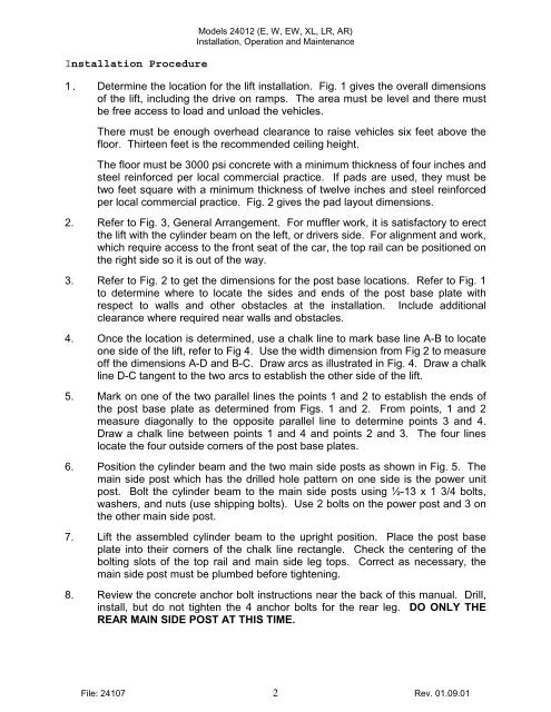
Installation Procedure<br />
Models 24012 (E, W, EW, XL, LR, AR)<br />
Installation, Operation and Maintenance<br />
1. Determine the location for the lift installation. Fig. 1 gives the overall dimensions<br />
of the lift, including the drive on ramps. The area must be level and there must<br />
be free access to load and unload the vehicles.<br />
There must be enough overhead clearance to raise vehicles six feet above the<br />
floor. Thirteen feet is the recommended ceiling height.<br />
The floor must be 3000 psi concrete with a minimum thickness of four inches and<br />
steel reinforced per local commercial practice. If pads are used, they must be<br />
two feet square with a minimum thickness of twelve inches and steel reinforced<br />
per local commercial practice. Fig. 2 gives the pad layout dimensions.<br />
2. Refer to Fig. 3, General Arrangement. For muffler work, it is satisfactory to erect<br />
the lift with the cylinder beam on the left, or drivers side. For alignment and work,<br />
which require access to the front seat of the car, the top rail can be positioned on<br />
the right side so it is out of the way.<br />
3. Refer to Fig. 2 to get the dimensions for the post base locations. Refer to Fig. 1<br />
to determine where to locate the sides and ends of the post base plate with<br />
respect to walls and other obstacles at the installation. <strong>Inc</strong>lude additional<br />
clearance where required near walls and obstacles.<br />
4. Once the location is determined, use a chalk line to mark base line A-B to locate<br />
one side of the lift, refer to Fig 4. Use the width dimension from Fig 2 to measure<br />
off the dimensions A-D and B-C. Draw arcs as illustrated in Fig. 4. Draw a chalk<br />
line D-C tangent to the two arcs to establish the other side of the lift.<br />
5. Mark on one of the two parallel lines the points 1 and 2 to establish the ends of<br />
the post base plate as determined from Figs. 1 and 2. From points, 1 and 2<br />
measure diagonally to the opposite parallel line to determine points 3 and 4.<br />
Draw a chalk line between points 1 and 4 and points 2 and 3. The four lines<br />
locate the four outside corners of the post base plates.<br />
6. Position the cylinder beam and the two main side posts as shown in Fig. 5. The<br />
main side post which has the drilled hole pattern on one side is the power unit<br />
post. Bolt the cylinder beam to the main side posts using ½-13 x 1 3/4 bolts,<br />
washers, and nuts (use shipping bolts). Use 2 bolts on the power post and 3 on<br />
the other main side post.<br />
7. Lift the assembled cylinder beam to the upright position. Place the post base<br />
plate into their corners of the chalk line rectangle. Check the centering of the<br />
bolting slots of the top rail and main side leg tops. Correct as necessary, the<br />
main side post must be plumbed before tightening.<br />
8. Review the concrete anchor bolt instructions near the back of this manual. Drill,<br />
install, but do not tighten the 4 anchor bolts for the rear leg. DO ONLY THE<br />
REAR MAIN SIDE POST AT THIS TIME.<br />
File: 24107 2 Rev. 01.09.01