

DEMO - 1972 Ford Car Shop Manual (Vol I-V) - ForelPublishing.com
DEMO - 1972 Ford Car Shop Manual (Vol I-V) - ForelPublishing.com
DEMO - 1972 Ford Car Shop Manual (Vol I-V) - ForelPublishing.com

Create successful ePaper yourself
Turn your PDF publications into a flip-book with our unique Google optimized e-Paper software.
, 11-02-02 Wheels And Tires-Drop Center Rim<br />
The Space Saver Spare can, in<br />
case of a puncture, be repaired the same<br />
as an original equipment tire.<br />
-<br />
FRONT WHEEL ASSEMBLY<br />
Each front wheel and tire is bolted<br />
to its respective front hub and brake<br />
drum or rotor assembly. Two opposed<br />
tapered roller bearings are installed in<br />
each hub. A grease retainer is installed<br />
at the inner end of the hub to prevent<br />
lubricant from leaking into the drum or<br />
on the rotor. The entire assembly is retained<br />
to its spindle by the adjusting nut,<br />
nut lock and cotter pin (Figs. 1 and 2).<br />
REAR WHEEL ASSEMBLY<br />
The rear wheel hub and brake<br />
drum assembly is attached to studs on<br />
the rear axle shaft flange by three speed<br />
nuts. The wheel and tire mounts on the<br />
same rear axle shaft flange studs and is<br />
held against the hub and drum by the<br />
wheel nuts. The rear wheel bearing is<br />
pressed onto the axle shaft just inside the<br />
shaft flange, and the entire assembly is<br />
retained to the rear axle housing by the<br />
bearing retainer plate which is bolted to<br />
the housing flange.<br />
4 REMOVAL AND INSTALLATION<br />
HOISTING INSTRUCTIONS<br />
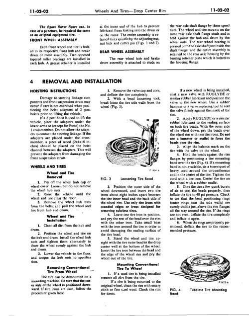
1. Remove the valve cap and core,<br />
and deflate the tire <strong>com</strong>pletely.<br />
Damage to steering linkage <strong>com</strong> 2. With a bead loosening tool,<br />
Ponents and front suspension struts may break lobse the tire side walls from the<br />
occur if care is not exercised when posi- wheel ( ~ i 3). ~ .<br />
tioning the hoist adapters of 2 post<br />
hoists prior to lifting the vehicle.<br />
If a 2 post hoist is used to lift the<br />
vehicle, place the adapters under the<br />
lower arms or (except for Pinto) the NO.<br />
1 crossmember. Do not allow the adapters<br />
to contact the steering linkage. If the<br />
adapters are placed under the crossmember,<br />
a piece of wood (2x4~16 inches)<br />
should be placed on the hoist<br />
channel between the adapters. This will<br />
prevent the adapters from damaging the<br />
front suspension struts.<br />
WHEELS AND TIRES<br />
Wheel and Tire<br />
Removal<br />
1. Pry off the wheel hub cap or<br />
wheel cover. Loosen but do not remove<br />
the wheel hub nuts.<br />
2. Raise the vehicle until the<br />
wheel and tire clear the floor.<br />
3. Remove the wheel hub nuts<br />
from the bolts, and pull the wheel and<br />
tire from hub and drum.<br />
Wheel and Tire<br />
Installation<br />
1. Clean all dirt from the hub and<br />
drum.<br />
2. Position the wheel and tire on<br />
the hub and drum. Install the wheel hub<br />
nuts and tighten them alternately to<br />
draw the wheel evenly against the hub<br />
and drum.<br />
3. Lower the vehicle to the floor,<br />
and torque the hub nuts to specifica<br />
tion.<br />
Removing Conventional<br />
Tire From Wheel<br />
The tire can be demounted on a<br />
mounting machine. Be sure that the outer<br />
side of the wheel is positioned downward.<br />
If tire irons are used, follow the<br />
procedure given here.<br />
/<br />
FIG. 3<br />
Loosening Tire Bead<br />
3. Position the outer side of the<br />
wheel downward, and insert two tire<br />
irons about eight inches apart between<br />
the tire inner bead and the back side of<br />
the wheel rim. Use only tire irons with<br />
rounded edges or irons designed for<br />
removing tubeless tires.<br />
4. Leave one tire iron in position,<br />
and pry the rest of the bead over the rim<br />
with the other iron. Take small bites<br />
with the iron around the tire in order to<br />
avoid damaging the sealing surface of<br />
the tire bead.<br />
5. Stand the wheel and tire upright<br />
with the tire outer bead in the drop<br />
center well at the bottom of the wheel.<br />
Insert the tire iron between the bead and<br />
the edge of the wheel rim and pry the<br />
wheel out of the tire.<br />
Mounting Conventional<br />
Tire To Wheel<br />
1. If a used tire is being installed<br />
remove all dirt from the tire.<br />
If a tire is being mounted to the<br />
original wheel, clean the rim with emery<br />
cloth or fine s.eel wool. Check the rim<br />
for dents. '<br />
If a new wheel is being installed,<br />
coat a new valve with RUGLYDE or<br />
similar rubber lubricant and position the<br />
valve to the riew wheel. Use a rubber<br />
hammer or a valve replacing tool to seat<br />
the valve firmly against the inside of the<br />
rim.<br />
2. Apply RUGLYDE or a sim ilar<br />
rubber lubricant to the sealing surface<br />
on both tire beads. With the outer side<br />
of the wheel down, pry the beads over<br />
the wheel rim with two tire irons. Do not<br />
use a hammer or mallet to force the<br />
beads over the rim.<br />
3. Align the balance mark on the<br />
tire with the valve on the wheel.<br />
4. Hold the beads against the rim<br />
flanges by positioning a tire mounting<br />
band over the tire (Fig. 4). If a mounting .<br />
band is not available, tie a tourniquet of<br />
heavy cord around the circumference<br />
and in the center of the tire. Tighten the<br />
cord with a tire iron. Center the tire on<br />
the wheel with a rubber mallet.<br />
5. Give the tire a few quick bursts<br />
of air to seat the beads properly, then<br />
inflate the tire to 40 psi pressure. Check<br />
to see that the bead positioning rings<br />
(outer rings near the side walls) are<br />
evenly visible just above the rim flanges<br />
all the way around the tire. If the rings<br />
are not even, deflate the tire <strong>com</strong>pletely<br />
and inflate it again.<br />
6. When the rings are properly positioned,<br />
deflate the tire to the re<strong>com</strong>mended<br />
pressure.<br />
FIG. 4<br />
Band<br />
Tubeless Tire Mounting


