

DEMO - 1972 Ford Car Shop Manual (Vol I-V) - ForelPublishing.com
DEMO - 1972 Ford Car Shop Manual (Vol I-V) - ForelPublishing.com
DEMO - 1972 Ford Car Shop Manual (Vol I-V) - ForelPublishing.com

You also want an ePaper? Increase the reach of your titles
YUMPU automatically turns print PDFs into web optimized ePapers that Google loves.
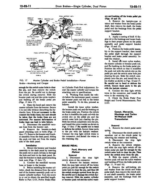
12-02- 1 1 Drum Brakes-Single Cylinder, Dual Pistori 1 2-02-1 1.<br />
MASTER CYLINDER MUST<br />
BE FRW FULL TO 0.15<br />
INCHES FROM TOP.<br />
BOOSTER CHECK<br />
PEDAL SUPPORT ASSY.<br />
l/B MAX. 6 FULL WIDTH OF CLMP<br />
ON HOSE INSTALLATION<br />
PEDAL WPPORT ASSY.<br />
LUTOl PEDAL ABY.<br />
BEND TABSPGAFTER ASSY.<br />
' NO PROJECTIONS PERMISSIBLE.<br />
(1 REQD.)<br />
VIEW A VIEW B n 1861.~<br />
FIG. 17 Master Cylinder and Brake Pedal Installation-Power<br />
BrakeMustang and Cougar<br />
enough for the switch outer hole to clear<br />
the pin, and then remove the switch<br />
from the pin. Be careful not to damage<br />
the switch during removal. Slide the<br />
booster push rod and the nyloh washers<br />
and bushing off the brake pedal pin<br />
(Figs. 15 thru 17).<br />
2. Open the hood and remove the<br />
master cylinder from the booster. Secure<br />
it to one side without disturbing the hydraulic<br />
limes. It Is not necessary to dlsconnect<br />
the brake Unea, but care should<br />
be taken that the brake llnea are not<br />
deformed. Per manent deformation of<br />
brake line8 can lead to tube failure.<br />
3. Disconnect the manifold vacuum<br />
hose from the booster unit.<br />
4. Rmiove the booster-to-dash<br />
panel attaching nuts or bolts (Figs. 15<br />
thru 17). Remove the booster and bracket<br />
assembly from the dash panel, sliding<br />
the push rod link out from the engine<br />
side of the dash panel.,<br />
Imtauatiop<br />
1. Mount the booster and bracket<br />
assembly to the dash panel by inserting<br />
the push rod or push rod link in through<br />
the hole and boot in the dash panel. Install<br />
the bracket-to-dash panel attaching<br />
lock nuts (Figs. 15 thru 1.7).<br />
2. Connect the manifold vacuum<br />
hose or hoses to the booster.<br />
3. Before installing the master cylinder,<br />
check the distance from the outer<br />
end of the booster assembly push rod to<br />
master cylinder surface. Turn the screw<br />
in or out to obtain the specified length.<br />
Refer to Part 12-01, Power Brake Mas-<br />
ter Cylinder Push Rod Adjustment. Install<br />
the master cylinder and torque the<br />
attaching nuts to specificatiops.<br />
4. Working from inside the vehicle<br />
below the instrument panel, connect<br />
the booster push rod link to the brake<br />
pedal assembly. To do this, proceed as<br />
follows:<br />
Install the inner nylon washer,<br />
the booster push rod, and the bushing on<br />
the brake pedal pin. Position the switch<br />
so that it straddles the push rod with the<br />
switch slot on the pedal pin and the<br />
switch oukr hole just clearing the pin.<br />
Slide the switch <strong>com</strong>pletely onio.the pin,<br />
and install the nylon washer as shown in<br />
Figs. 15 thru li.~e careful not to bend<br />
or deform the switch. Secure these parts<br />
to the pin with the hairpiin retainer.<br />
Connect the stop light switch wires to<br />
the connector, and.&stall the wires in<br />
the retaining clip.<br />
BRAKE PEDAL<br />
<strong>Ford</strong>, Mercury and<br />
Meteor<br />
Removal<br />
1. Disconnect the stop light<br />
switch wires at the connector.<br />
2. Remove the hairpin retainer.<br />
Slide the stop light switch off the brake<br />
pedal pin just far enough for the switch<br />
outer hole to clear the pin, and then lift<br />
the switch straight upward from the pin.<br />
Be careful not to damage the switch during<br />
removal. Slide the master cylinder<br />
or booster push rod and the nylon wash-<br />
ers and bushlng off the brake pehd pin<br />
(Figs. 10 and 15).<br />
3. Remove the hairpin-type re<br />
tainer and washer from the brake pedal<br />
shaft, then remove the shaft, the brake<br />
pedal and the bushings from the pedal<br />
support bracket.<br />
Installation<br />
1. Apply a coating of SAE 10 Engine<br />
oil to the bushings and locate bushings<br />
in their propr places on the pedal<br />
assembly and pedal support bracket<br />
(Figs. 10 and 15).<br />
2. Position the brake pedal assembly<br />
to the support bracket, then install<br />
the pedal shaft through the support<br />
bracket and brake pedal assembly. Install<br />
the retciiner.<br />
3. Install thk inner nylon washer,<br />
the master cylinder or booster push rod,<br />
and tAe bushing on the brake pedal pin.<br />
Position the switch so that it straddles<br />
the push rod with the switch slot on the<br />
pedal pin and the switch outer hole just<br />
clearing the pin. Slide the switch wmpletely<br />
onto the pin, and install the nylon<br />
washer as shown in Figs. 10 and 15.<br />
Be careful not to bend or deform the<br />
switch. Secure these parts to the pin<br />
with the hairpin retainer.<br />
4. Connect the stop light switch<br />
wires to the connector, and install the<br />
wires in the retaining clip.<br />
5. Check the Brake Pedal ' Free<br />
Height and Travel Measurements, Part<br />
12-01.<br />
Comet, Maverick,<br />
Montego and Torino<br />
W/<strong>Manual</strong> Shifi<br />
Transmission<br />
Removal<br />
1. Remove the clutch pedal assist<br />
spring.<br />
2. Disconnect the clutch pedal t&<br />
equalizer rod at the clutch pedal by<br />
removing the retainer and bushing.<br />
3. Disconnect the stop light<br />
switch wires at the connector.<br />
4. Remove the switch retainer,<br />
and slide the stop light switch off. the<br />
brake pedal pin just far enough for the<br />
switch outer hole to clear the pin. Then<br />
lower the switcb away from the pin.<br />
5. Slide the master cylinder or<br />
booster push rod and the nylon washers<br />
and bushing off from the brake pedal pin<br />
(Figs. 11, 14 and 16).<br />
6. Remove the self-locking pin<br />
and washer from the clutch and brake<br />
pedal shaft, then remove the clutch pedal<br />
and shaft assembly, the brake pedal<br />
assembly, and the bushings from the<br />
pedal support bracket.


