The sound - MuleSlow Services
The sound - MuleSlow Services
The sound - MuleSlow Services

You also want an ePaper? Increase the reach of your titles
YUMPU automatically turns print PDFs into web optimized ePapers that Google loves.
cilloscope is a voltage measuring instrument,<br />
it is almost impossible to<br />
observe internal transient overshoot<br />
problems in such amplifiers without<br />
their modification or the use of expensive<br />
current probes.<br />
In this article, a practical design example<br />
is presented which is based almost<br />
entirely on the design philosophy<br />
presented in the previous article.<br />
Since each internal stage in this amplifier<br />
utilizes local negative current<br />
feedback, the impedance levels in the<br />
amplifier are sufficiently high and the<br />
feedback ratio is sufficiently low so<br />
that the transient response of each internal<br />
stage can be measured easily<br />
with an oscilloscope. <strong>The</strong> circuit has<br />
been carefully designed so that transient<br />
inter-loop signal overload cannot<br />
occur, even with ultra-fast risetime<br />
square-wave signals applied to<br />
the amplifier input. Since no internal<br />
stage is subject to transient overload<br />
problems, the amplifier is theoretically<br />
free of TIM distortion, and the results<br />
can be startlingly audible, especially<br />
with full-range electrostatic<br />
speakers.<br />
When used within its power limitations,<br />
the amplifier can be used with<br />
the finest associated equipment. In<br />
several subjective listening tests, it has<br />
audibly equaled or surpassed any amplifier<br />
to which it has been compared.<br />
<strong>The</strong> audible differences are greatest<br />
during music which contains loud<br />
high-frequency material and percussive<br />
<strong>sound</strong>s. <strong>The</strong>se differences are<br />
attributed to the controlled inter-loop<br />
transient response of the amplifier<br />
and the lack of TIM distortion in the<br />
reproduced music. <strong>The</strong>se are principally<br />
a direct result of the fact that the<br />
open-loop frequency bandwidth is<br />
38,000 Hz or approximately twice that<br />
of the audible spectrum.<br />
<strong>The</strong> amplifier is a fully complementary-symmetry,<br />
directcoupled<br />
design. It has a closed-loop<br />
frequency response which extends<br />
from approximately 0.5 Hz to 150,000<br />
Hz. <strong>The</strong> response outside these limits<br />
has been intentionally rolled off. Otherwise,<br />
the small-signal frequency response<br />
would extend from d.c. to<br />
over 800,000 Hz. With the specified<br />
power supply, the power output is 70<br />
watts per channel, both channels<br />
driven simultaneously, or 84 watts<br />
from either channel driven alone.<br />
Both the 1M distortion (SMPTE Standard)<br />
and the THO are less than 0.2%<br />
at 70 watts or less, where the THO is<br />
measured at any frequency between<br />
20 Hz and 20,000 Hz. At lower power<br />
levels, the distortion is much lower,<br />
typically 0.04% or less. However, no<br />
ultra-low distortion levels are claimed<br />
since an unrealistically low THD specification<br />
can indicate the presence of<br />
TIM distortion in an amplifier<br />
[2). With the feedback loop disconnected,<br />
the amplifier will produce<br />
50 watts into an 8-ohm load with a<br />
THD of only 0.5% at 1000 Hz. This low<br />
distortion is indicative of the inherent<br />
linearity of the open-loop amplifier.<br />
Thus, the addition of negative feedback<br />
has not been used to "clean up"<br />
problems of the basic design, but to<br />
improve it. As the power level is decreased,<br />
both the 1M distortion and<br />
THO decrease monotonically. This indicates<br />
the absence of crossover distortion.<br />
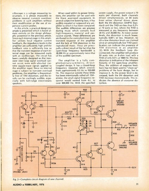
~--'-----------~------------~+----------~JV~--,-------,-------~----~-+-----o+50V<br />
R6<br />
I<br />
C4<br />
R22<br />
C7<br />
I<br />
CIRCUIT<br />
BOARD<br />
GROUND<br />
R33 CIO<br />
R20<br />
R35<br />
R34<br />
SPEAKER<br />
OUTPUT<br />
R2<br />
w<br />
..J<br />
m<br />