Daito 9F-7R5F Technical Service Data - MuleSlow Services
Daito 9F-7R5F Technical Service Data - MuleSlow Services
Daito 9F-7R5F Technical Service Data - MuleSlow Services

Create successful ePaper yourself
Turn your PDF publications into a flip-book with our unique Google optimized e-Paper software.
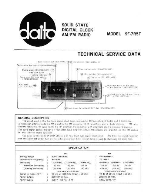
SOLID STATE<br />
DIGITAL CLOCK<br />
AM/FM RADIO<br />
MODEL <strong>9F</strong>-<strong>7R5F</strong><br />
TECHNICAL SERVICE DATA<br />
Back cabinet (20220010612)<br />
Back plate for clock (25429084804)<br />
Digital clock (06420035391)<br />
Time and alarm<br />
setting indicator<br />
Clock knob for time set<br />
(25660084806)<br />
Escutcheon (21113010611)<br />
Transparent plate (22000022007)<br />
Dial pointer (40140081871)<br />
Dial scale (22132035648)<br />
A. C. cord<br />
(05412041257)<br />
Switch knob for FM and<br />
AM selector (04514033784)<br />
Knob ass'y for VR and Tunig<br />
(27111083394)<br />
Clock knob for Auto ON OFF SW (25660084805)<br />
GENERAL DESCRIPTION<br />
The circuit used in this two band digital clock radio incorporates 10 transistors, 6 diodes and 1 thermistor.<br />
A ferrite bar antenna feeds the AM signal to the AM converter, 2 IF amplifiers and a diode detector. FM wire<br />
antenna feeds the FM signal to the FM RF amplifier, FM converter, 3 IF amplifiers and FM detector (2 diodes.)<br />
The audio signal passes through a 4 transistor audio amplifier circuit. AFC circuits are provided on the FM section<br />
of this radio for stable operation<br />
The clock for the Model <strong>9F</strong>-<strong>7R5F</strong> utilizes a 24-hour drum type digital mechanism. The time set switch together<br />
with the alarm set switch turn on the radio at a pre-set time. A neon lamp is used to illuminate the clock face.<br />
SPECIFICATION<br />
AM<br />
FM<br />
Tuning Range 520~1680 KHz 87~109 MHz<br />
Intermediate Frequency 455 KHz 10.7 MHz<br />
Sensitivity (600 KHz), (1000 KHz), (1400 KHz), (90 MHz), (98 MHz), (106 MHz),<br />
Maximum Sensitivity 52 db 52 db 52 db 24 db 24 db 24 db<br />
Quieting Sensitivity (60 db) (60 db) (60 db)<br />
(29 db) (29 db) (29 db)<br />
(AM band at S/N 20 db)<br />
(FM band at S/N 30 db)<br />
Signal to noise (S/N) 20 db at 1000 KHz (Input ; 60 db) 40 db at 98 db (Input ; 60 db)<br />
Power Output 280 mW at max. 280 mW at max.<br />
Power Supply 120 V, 60 Hz, 6 W 120V, 60Hz, 6W
OPERATING INSTRUCTIONS<br />
Preparations<br />
Place the plug into a receptacle fl 10-120 V, 60 Hz ac source : the clock will run immediately.<br />
Depress knob No. and turn it to set correct time on the indicator.<br />
Knob No. will return to its resting position when it is recased.<br />
Radio Part<br />
Place knob No. in the "ON" position. The desired range is selected with the pushbutton<br />
Pushbutton No. depressed = AM<br />
Pushbutton No. not depressed = FM<br />
This receiver is equipped with a FM wire antenna. The best receiver performance is achieved by extending the antenna,<br />
which is pulled from the bottom of the cabinet to its full length.<br />
The set is tuned to a station with the aid of knob No. -B, the volume control is accomplished with knob No. -A.<br />
The set is turned off by placing knob No. is the "OFF" position.<br />
Alarm Clock Combined with Radio<br />
1. Waking up to Music<br />
(a) Tune to station and adjust volume as described under "Radio".<br />
(b) Turn knob No. clockwise to select the time on the indicator for the alarm when it is desired to go on.<br />
The indicator for the alarm is calibrated by 10-minute intervals.<br />
(c) Place knob No. in the "AUTO" position.<br />
(d) The radio will start playing at the selected time (refer to item (b), above). It can be turned off by placing knob<br />
No. in the "OFF" position.<br />
2 Waking up to Music and Alarm<br />
(a) Tune the radio as described under "Radio Part".<br />
(b) Set the alarm (refer to "Waking up to Music", Item (b), above).<br />
(c) Place knob No. in the "Alarm" position.<br />
(d) At the selected time, the radio will wake up with the broadcast and the alarm will start ringing.<br />
(e) The alarm can be turned off by turning knob No. to the "AUTO" position. In that case the radio will continue<br />
to play. If it is desired to turn off the radio broadcast too, knob No. must be placed in the "OFF" position.<br />
3. Waking up to Alarm Only<br />
(a) Turn the volume control knob No. -A to its MAX COUNTER CLOCKWISE POSITION.<br />
(b) Select the wake-up time with knob No.<br />
(c) Return knob No. to the "ALARM" position.<br />
START<br />
DRUM<br />
SPRING<br />
POINTER<br />
TUNING<br />
SHAFT<br />
3 1/2 TURNS<br />
— 1 —
SECTION II<br />
GENERAL ALIGNMENT INSTRUCTIONS<br />
Should it become necessary at any time to check the alignment of this receiver, proceed as follows:<br />
1. Connect an A.C. V.T.V.M. across the speaker voice coil.<br />
2. Set volume control to maximum (fully clockwise).<br />
3. Keep signal input at a low level to avoid AGC action.<br />
4. Use a non-metallic alignment tool.<br />
5. Signal generator and meters should be isolated from ground of house wiring during alignment.<br />
Set band select switch to the AM positon.<br />
AM ALIGNMENT<br />
CHART<br />
Step<br />
1<br />
2<br />
3<br />
Signal generator<br />
Receiver<br />
Connection to receiver Input signal freq. Dial setting Remarks<br />
Connect the signal generator<br />
through a 0.01<br />
MF<br />
capacitor to VC3, Connect<br />
the ground lead to<br />
the chassis ground.<br />
Exactly 455 KHz<br />
Quiet point on dial<br />
(400 Hz, 30%, AM<br />
near 1600 KHz<br />
modulated)<br />
Adjust for maximum<br />
needle deflection<br />
on A. C.<br />
V. T. V. M. connected<br />
across speaker<br />
4 Repeat steps 1, 2, and 3 until no further improvement in sensitivity can be made.<br />
Adjustment<br />
AM. IFT (T-8)<br />
AM, IFT (T-7)<br />
AM, IFT (T-6)<br />
5<br />
6<br />
7<br />
Use radiation loop. Loop<br />
of several turns of wire<br />
connected across generator<br />
leads. Place loop<br />
close to the ferrite bar<br />
antenna for adequate<br />
signal pick-up.<br />
Exactly 1680 KHz<br />
(400 Hz, 30%, AM<br />
modulated)<br />
Exactly 520 KHz<br />
(400 Hz, 30%, AM<br />
modulated)<br />
Exactly 1400 KHz<br />
(400 Hz, 30%, AM<br />
modulated)<br />
Exactly 600 KHz<br />
Tuning gang fully<br />
open<br />
Tuning gang fully<br />
closed<br />
1400 KHz<br />
Adjust for maximum<br />
need!e deflection<br />
on A. C.<br />
V. T. V. M. connected<br />
across speaker<br />
TC4 (OSC. trimmer)<br />
AM OSC. coil (L-8)<br />
TC3 (ANT. trimmer)<br />
8<br />
(400 Hz, 30%, AM<br />
modulated)<br />
600 KHz<br />
AM ANT. coil (L-7)<br />
9 Repeat steps 5, 6, 7 and 8 until no further improvement in sensitivity can be made.<br />
Set band select switch to the FM position.<br />
FM ALIGNMENT<br />
CHART<br />
Step<br />
Signal generator<br />
Receiver<br />
Connection to receiver lnput signal freq. Dial setting Remarks<br />
Adjustment<br />
1<br />
2<br />
3<br />
A<br />
5<br />
6<br />
7<br />
Connect the signal generator<br />
across C12 through<br />
a 0.001 MF capacitor.<br />
Exactly 10.7 MHz<br />
modulated<br />
400 Hz, 22.5 KHz<br />
deviation<br />
FM modulated<br />
Quiet point on dial<br />
D.C. probe of<br />
V.T.V.M. across<br />
C29 Adjust for<br />
FM, IFT T-5<br />
FM, IFT T-4<br />
FM, IFT T-3<br />
maximum<br />
deflection<br />
FM, IFT T-2<br />
of needle.<br />
FM- IFT T-1<br />
Repeat steps 1, 2, 3, 4 and 5.<br />
D.C. probe of<br />
Adjust T5<br />
V.T.V.M. across<br />
for zero V.T.V.M<br />
C29<br />
8<br />
9<br />
10<br />
11<br />
Connect high side of<br />
signal generator to junction<br />
of C1 and C2<br />
Connect ground lead to<br />
chassis ground.<br />
Exactly 87 MHz<br />
modulated as above<br />
Exactly 110 MHz<br />
modulated as above<br />
Exactly 90 MHz<br />
modulated as above<br />
Exactly 106 MHz<br />
modulated as above<br />
Tuning gang<br />
fully closed Adjust for maxmum<br />
Tuning gang<br />
fully open<br />
needle deflection<br />
on A. C.<br />
V.T.V.M. connec<br />
90 MHz<br />
ted across<br />
speaker<br />
106 MHz<br />
FM OSC. coil (L-3)<br />
TC2 (FM OSC.<br />
trimmer)<br />
FM RF coil (L-2)<br />
TC29 (FM RF<br />
trimmer)<br />
12 Repeat steps 8, 9, 10 and 11 until on further improvement in sensitivity can be made.<br />
— 2 —
DISASSEMBLY<br />
Remove 2-screws ~ on the bottom of back cabinet and<br />
separate the back cabinet from unit.<br />
Remove 2-screws<br />
SECTION III<br />
REALIGNMENT<br />
Push-out transparent plate No. with screwdriver for changing<br />
new parts, (change to new Dial-scale or new back plate<br />
for clock or new Digital-clock), after pull-out knobs (No. ,<br />
and )<br />
Transparent plate<br />
Push<br />
Out<br />
FM.ANT<br />
AC Cord<br />
Remove a screw on the escutcheon's Leg for repairing<br />
radio circuit.<br />
Pull-out Dial-scale with your finger.<br />
Remove a screw<br />
Clock Pull-out Dial scale No. 4<br />
Circuit<br />
Ass'y<br />
Remove 2-screws ~ on the escutcheon's leg, and also<br />
remove 2-screws ~ on the back cabinet, for changing<br />
new speaker.<br />
Remove 4-screws ~ with screw-driver.<br />
Remove 2 screws<br />
Speaker<br />
Remove 4-Screws<br />
Tuning shaft<br />
No. 6 B<br />
VR No.6 A<br />
Back plate<br />
No.5<br />
Remove 2 screws<br />
Clock<br />
— 3 —
SECTION IV<br />
WIRING DIAGRAM<br />
NOTE<br />
L7 : AM BAR ANT COIL<br />
L8 : AM O.S.C COIL<br />
T6 : AM I.F.T<br />
T7 : AM I.F.T<br />
T8 : AM I.F.T (DET.)<br />
L1 : FM ANT COIL<br />
L2 : FM RF COIL<br />
L3 : FM O.S.C COIL<br />
L4 : FM TRAP (107 MHZ)<br />
T1 : FM I.F.T<br />
T2 : FM I.F.T<br />
T3 : FM I.F.T<br />
T4 : FM I.F.T<br />
T5 : FM I.F.T (DET)<br />
— 4 —
SECTION<br />
V-A<br />
SERVICE PARTS LIST<br />
(For CIRCUIT COMPONENTS)<br />
Code No. Symbol No. Description<br />
16103190930 Q1 Transistor 2SC930D FM, RF<br />
16104190930 02 " 2SC930E FM, OSC<br />
16103190930 Q3 " 2SC930D AM, Converter<br />
16104190930 Q4, 5 " 2SC930E I.F.<br />
16308290537 Q6 " 2SC537G1 AF<br />
16309290537 Q7 " 2SC537G2 Driver<br />
16202190187}<br />
16203190187}<br />
Q8, 9<br />
16411190188 D1, 5 Diode 1S-188 AM<br />
16405990022 D2 " CDG 22<br />
16401190188 D3, 4 " 1S-188 FM<br />
16540881851 D5, 6 Selenium BST10A102<br />
16633992500 TH Thermister 250ohm<br />
00041047001 L1 FM ANT Coil<br />
00042082038 L2 FM RF Coil<br />
00041047000 L3 FM Converter Coil<br />
00021142287 L4. 5, 6 IF Trap Coil<br />
00511081852 L7 AM ANT Coil<br />
00300081853 L8 AM OSC Coil<br />
00100081854 T1 FM IFT (A)<br />
00102081855 T2 FM IFT (B)<br />
00102081855 T3 FM IFT (C)<br />
00104081857 T4 FM IFT (D)<br />
00105081858 T5 FM IFT (E)<br />
00700081859 T6 AM IFT (A)<br />
00701081860 T7 AM IFT (B)<br />
00702081861 T8 AM IFT (C)<br />
10202081863 T9 Input Transformer<br />
15000033747 P. C. B.<br />
08543042135 VC P. V. C<br />
01156081812 VR VR<br />
31340082096 Spacer<br />
04514033784 Switch<br />
43591549550 Spring<br />
40421133960 Drum for Tuning<br />
40305281865 Shaft<br />
49023981867 Chassis Ass'y<br />
50014181870 Bracket for SW.<br />
40140081871 Pointer<br />
41233281873<br />
45020092605<br />
Ant. Holder<br />
Screw for P. V. C. fitting<br />
2.6x5%<br />
45030092005 Screw for bracket 2x5%<br />
45020092005 Screw for ANT. Holder and chassis fitting 2x5%<br />
45501592000 Nut for ANT. Holder and chassis fitting 2<br />
45020092605 Screw for drum 2.6x5%<br />
63059133800 Snow box (upper)<br />
63059233801 Snow box (bottom)<br />
64212252280 Poly bag<br />
12312094706 C41, 42 Capacitor, Electrolytic 470uF/10V<br />
12312092206 C38 " " 220uF/10V<br />
12312091006 C40 " " 100uF/10V<br />
— 5 —
SECTION<br />
V-B<br />
SERVICE PARTS LIST<br />
(For CIRCIT COMPONENTS)<br />
Code No. Symbol No. Description<br />
12311092205 C39 Capacitor, Electrolytic 22uF/6V<br />
12312094704 C24, 26 " " 4.7uF/10V<br />
12131295002 C35 " Mylar 0.5uF<br />
12201092000 C47 Capacitor, Styrol 200PF ±5%<br />
12131291002 C32 " , Mylar 0.01uF<br />
00021088633 L9 Choke Coil 5uH<br />
12201091400 C33 Capacitor, Styrol 140PF ±5%<br />
12501592002 C16 Capacitor, Ceramic 0.02uF<br />
12501892002<br />
C13, 14, 17, 19, 20, 21.<br />
C23, 25, 30, 34<br />
" " 0.02uF +100%/-20%<br />
12501895001 C29, 28 " " 0.005uF<br />
12501892001 C37 " " 0.002uF<br />
12501891001 C2, 3, 11. 15, 43 " " 0.001uF<br />
12501495000 C8, 45 " " 500PF ±10%<br />
12501493500 C27 " " 350PF<br />
12501391500 C5 " " 150PF ±5%<br />
12501391000 C36. 44 " " 100PF<br />
12501390950 C1O " " 95PF<br />
12501390450 C9 " " 45PF<br />
12501390200 C1 " " 20PF<br />
12501090150 C4 " " 15PF ±0.5PF<br />
12501090030 C6 " " 3PF ±0.5PF<br />
12501090020 C22, 18 " " 2PF ±0.5PF<br />
12501490300 C31 " " 30PF ±10%<br />
12501090060 C7 " " 6PF ±0.5PF<br />
12501090100 C12, 46 " " 10PF ±0.5PF<br />
11144690330 R42 Resistor 1/4W 33ohm<br />
11044690220 R39 " " 22Kohm<br />
11044695600 R30 " " 560Kohm<br />
11044694700 R23 " " 470Kohm<br />
11044691002 R20 " " 10Kohm<br />
11144692203 R4, 27 " " 220Kohm<br />
11144691503 R21, 2, 24 " " 150Kohm<br />
11144691003 R5 " " 1OOKohm<br />
11144693903 R1O " " 390Kohm<br />
11144698202 R43 " " 82Kohm<br />
11144691202 R26 " " 12Kohm<br />
11144691002 R17 " " 10Kohm<br />
11144694701 R6, 18 " " 4.7Kohm<br />
11144691801 R35, 36 " " 1.8Kohm<br />
11144691501 R15, 16 " " 1.5Kohm<br />
11144691001 R1, 3, 7, 13, 19 " " 1Kohm<br />
11144691500 R8 " " 150ohm<br />
11144698200 R12 " " 820ohm<br />
11144695600 R28 " " 560ohm<br />
11144694700 R11 " " 470ohm<br />
11144693300 R32 " " 330ohm<br />
11144692200 R9, 25, 33, 37, 40, 41 " " 220ohm<br />
11144691000 R14, 31 " " 100ohm<br />
11144690100 R22, 29 " " 10ohm<br />
11144690022 R34, 38 " " 2.2ohm<br />
14123084759 Neon Lamp (117V) use clock Lamp<br />
— 6 —
SECTION<br />
V-C<br />
SERVICE PARTS LIST<br />
(For CABINET COMPONENTS)<br />
Code No. Symbol No. Description<br />
10061036176 Power transformer<br />
05412041257 A. C. cord<br />
21113010611 Escutcheon<br />
20220010612 Back cabinet<br />
22000022007 Transparent Board<br />
22132035648 Dial scale<br />
25429084804 Back plate for clock<br />
25660084805 Clock knob for Auto-OFF-ON SW.<br />
25660084806 Clock knob for time set SW.<br />
27111083394 Knob ass'y for VR and Tuning control<br />
50104584305 Nut<br />
50103784295 Nut<br />
43299983236 Bracket for SP fitting<br />
31461248000 Cushion<br />
06420035391 Digital clock ass'y<br />
63035122154 Snow box<br />
64330083238 Poly bag<br />
64210152268 Poly bag<br />
61082035649 Gift box<br />
60005035650 Master carton<br />
60005035651 Shipping carton<br />
SECTION VI<br />
SCHEMATIC DIAGRAM<br />
TOYO<br />
RADIO CO, OF AMERICA, INC.<br />
DISTRIBUTED BY TOYO<br />
TOYO RADIO COMPANY OF AMERICA, INCORPORATED<br />
MANUFACTURERS OF HOME ENTERTAINMENT PRODUCTS<br />
ADDRESS: 1842-B WEST 169TH STREET GARDENA, CALIFORNIA 90247<br />
TELEPHONE: (213) 321-4072 - TELEX - 67-3264<br />
Printed in Japan<br />
75610 041172