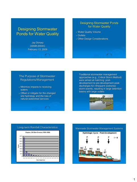
Designing Stormwater Ponds for Water Quality - Ohio EPA
Designing Stormwater Ponds for Water Quality - Ohio EPA
Designing Stormwater Ponds for Water Quality - Ohio EPA

Create successful ePaper yourself
Turn your PDF publications into a flip-book with our unique Google optimized e-Paper software.
Count<br />
<strong>Designing</strong> <strong>Stormwater</strong><br />
<strong>Ponds</strong> <strong>for</strong> <strong>Water</strong> <strong>Quality</strong><br />
Jay Dorsey<br />
ODNR-DSWC<br />
February 13, 2008<br />
<strong>Designing</strong> <strong>Stormwater</strong> <strong>Ponds</strong><br />
<strong>for</strong> <strong>Water</strong> <strong>Quality</strong><br />
‣ <strong>Water</strong> <strong>Quality</strong> Volume<br />
‣ Outlets<br />
‣ Other Design Considerations<br />
The Purpose of <strong>Stormwater</strong><br />
Regulations/Management<br />
‣ Minimize impacts to receiving<br />
waters<br />
‣ Offset or mitigate <strong>for</strong> the changed<br />
site hydrology and the loss of<br />
natural watershed services<br />
Traditional stormwater management<br />
approaches (e.g., Critical Storm Method)<br />
were aimed at matching postdevelopment<br />
to pre-development peak<br />
discharges <strong>for</strong> infrequent (extreme)<br />
storm events, resulting in large detention<br />
basins with large outlets<br />
Long-term Rainfall Characteristics<br />
Manmade <strong>Stormwater</strong> Management Systems<br />
Dayton, OH Rain Events (1950-1999)<br />
4000<br />
3500<br />
3000<br />
2500<br />
2000<br />
1500<br />
1000<br />
500<br />
0<br />
0.2 0.4 0.6 0.8 1.0 1.2 1.4 1.6 1.8 2.0 2.5 3.0 3.5 4.0 5.0<br />
Rain Depth (in)<br />
1
Cumulative Occurrence Probability<br />
%<br />
<strong>Stormwater</strong> Management<br />
Regulation in <strong>Ohio</strong><br />
Problems/concerns with peak discharge control<br />
methods (e.g., Critical Storm Method)<br />
‣ Problem 1: Too little detention time <strong>for</strong><br />
effective pollutant removal<br />
‣ Problem 2: Peak discharge control methods<br />
allow smaller rainfall events to become<br />
channel eroding events<br />
<strong>Ohio</strong> Application of WQv Formula<br />
<strong>Water</strong> <strong>Quality</strong><br />
Volume (WQv)<br />
‣ Urban Runoff <strong>Quality</strong><br />
Management, ASCE Manual<br />
of Practice No. 87, Amercan<br />
Society of Civil Engineers,<br />
Reston, VA, (1998).<br />
‣ WQv = C * P * A / 12<br />
Where:<br />
WQv = water quality volume (ac-ft)<br />
‣ C = runoff coefficient<br />
‣ P = 0.75 inch precipitation<br />
‣ A = area draining to the BMP (acres)<br />
Why 0.75” Rainfall Depth?<br />
Clarification of WQv<br />
Dayton, OH Rain Events (1950-1999)<br />
100<br />
90<br />
80<br />
70<br />
60<br />
50<br />
40<br />
30<br />
20<br />
10<br />
0<br />
0 0.5 1 1.5 2 2.5 3<br />
Rain Depth (in)<br />
‣ Runoff Coefficient<br />
‣ Drawdown Requirement<br />
2
Runoff Coefficient<br />
Runoff Coefficient<br />
WQv Runoff Coefficient<br />
WQv Runoff Coefficient<br />
1.00<br />
0.90<br />
0.80<br />
0.70<br />
0.60<br />
0.50<br />
0.40<br />
0.30<br />
WQv Runoff Coefficent<br />
C<br />
C = runoff coefficient<br />
i = watershed<br />
imperviousness ratio<br />
(percent total<br />
imperviousness<br />
divided by 100)<br />
C<br />
0.858i<br />
3<br />
C = runoff coefficient<br />
0.78i<br />
2<br />
0.774i<br />
i = watershed imperviousness ratio (percent total<br />
imperviousness divided 100)<br />
0.04<br />
0.20<br />
0.10<br />
0.00<br />
0.0 20.0 40.0 60.0 80.0 100.0<br />
Impervious Area (%)<br />
C<br />
0.858i<br />
3<br />
0.78i<br />
2<br />
0.774i<br />
0.04<br />
Source: Urban Runoff<br />
<strong>Quality</strong> Management,<br />
ASCE, 1998, p. 175.<br />
Example<br />
WQv Formula<br />
Determine the Runoff Coefficient, C, <strong>for</strong>:<br />
‣ 100 acre residential development, 0.5 acre<br />
lots, with 20% impervious area (i = 0.20)<br />
C = 0.17<br />
WQv = C * P * A / 12 = (0.17*0.75*100)/12 = 1.06 ac-ft<br />
From Example 1, using Table 1 value of C = 0.8,<br />
WQv = C * P * A / 12 = (0.3*0.75*100)/12 = 1.88 ac-ft<br />
‣ WQv = C * P * A / 12<br />
Where:<br />
WQv = water quality volume (ac-ft)<br />
‣ P = 0.75 inch precipitation<br />
‣ A = area draining to the BMP (acres)<br />
‣ C = runoff coefficient - ????<br />
Runoff Coefficient Comparison<br />
Runoff Coefficient Comparison<br />
Runoff Coefficent Comparison<br />
Calculated<br />
Published<br />
1.000<br />
0.900<br />
0.800<br />
0.700<br />
0.600<br />
0.500<br />
0.400<br />
0.300<br />
0.200<br />
0.100<br />
0.000<br />
0.0 20.0 40.0 60.0 80.0 100.0<br />
Impervious Area (%)<br />
CGP-C<br />
C<br />
Impervious Runoff Runoff Calc Publ Increase<br />
Area Coefficient Coefficient WQv WQv WQv<br />
SLU - Standard Land Use % C C acre-ft acre-ft %<br />
Urban Open Space 4.9 0.08 0.20 0.5 1.25 163<br />
Urban Parks 9.6 0.11 0.20 0.7 1.25 85<br />
Low Density Residential 20.3 0.17 0.30 1.1 1.875 74<br />
Med Density Res no alleys 37.7 0.27 0.40 1.7 2.5 50<br />
Duplex 39.1 0.27 0.50 1.7 3.125 82<br />
High Density Res no alleys 53.0 0.36 0.50 2.2 3.125 39<br />
Multi-Family Res no alleys 53.1 0.36 0.50 2.2 3.125 39<br />
Medium Industrial 68.5 0.48 0.80 3.0 5 67<br />
Office Park 73.1 0.52 0.80 3.3 5 53<br />
Strip Commercial 90.7 0.74 0.80 4.6 5 8<br />
3
Runoff Coefficient Comparison<br />
C Determination Method<br />
Land Use % Impervious Runoff Coefficient Wqv Increase TSS<br />
TSS<br />
(ac-ft) in Wqv (lb/ac/yr) Reduction<br />
(%)<br />
(%)<br />
No Pond 54.3 -<br />
‣ Recommendation – Use the <strong>for</strong>mula, not the<br />
Table<br />
Urban Open Space 4.9<br />
Calc 0.08 0.5 - 9.0 83.5<br />
Publ 0.20 1.25 163 9.3 83.0<br />
Duplex 39.1<br />
No Pond 280 -<br />
Calc 0.27 1.7 - 59.5 78.8<br />
C<br />
0.858i<br />
3<br />
0.78i<br />
2<br />
0.774i<br />
0.04<br />
Publ 0.50 3.12 82 57.3 79.6<br />
No Pond 703 -<br />
Medium Industrial 68.5<br />
Calc 0.48 3.0 - 139 80.3<br />
Publ 0.80 5.0 67 132 81.2<br />
Adjustments to WQv Formula<br />
Wet <strong>Ponds</strong><br />
Adjustments to WQv Formula<br />
Structural BMPs (excl Wet <strong>Ponds</strong>)<br />
O<strong>EPA</strong>-CGP p22<br />
O<strong>EPA</strong>-CGP p22<br />
Discharge Rate<br />
Sediment Settling Process<br />
‣ How quickly do we release the WQv to<br />
meet our stormwater management goals?<br />
Pond<br />
Inflow<br />
v w<br />
v s<br />
Permanent Pool/Sediment Storage<br />
Pond<br />
Discharge<br />
4
Volume (cu ft)<br />
Volume (cu ft)<br />
Pond<br />
Inflow<br />
Sediment Settling Process<br />
Sediment Settling Process<br />
Pond<br />
Inflow<br />
v w<br />
v w<br />
v s<br />
v s<br />
Pond<br />
Pond<br />
Permanent Pool/Sediment Storage<br />
Discharge<br />
Discharge<br />
v sand v silt v clay<br />
O<strong>EPA</strong> CGP Drawdown Requirements<br />
‣ The O<strong>EPA</strong> CGP lists drain time<br />
(or drawdown) requirements <strong>for</strong><br />
structural BMPs (CGP – Table 2)<br />
Select an appropriate outlet to<br />
meet drawdown requirement <strong>for</strong><br />
wet ponds and dry ponds<br />
Volume vs Drawdown Time<br />
Volume vs Drawdown Time<br />
45,000<br />
45,000<br />
40,000<br />
40,000<br />
35,000<br />
35,000<br />
30,000<br />
30,000<br />
25,000<br />
4.5" Outlet<br />
25,000<br />
4.5" Outlet<br />
20,000<br />
8" Outlet<br />
20,000<br />
8" Outlet<br />
15,000<br />
15,000<br />
10,000<br />
10,000<br />
5,000<br />
5,000<br />
0<br />
0<br />
0 10 20 30 40 50 60 70 80<br />
0 10 20 30 40 50 60 70 80<br />
Drawdown Time (hr)<br />
Drawdown Time (hr)<br />
5
Volume (cu ft)<br />
Volume (cu ft)<br />
Volume (cu ft)<br />
Volume (cu ft)<br />
Volume vs Drawdown Time<br />
Volume vs Drawdown Time<br />
45,000<br />
WQv<br />
The WQv orifice should be sized to release no more<br />
than one-half the WQv (0.5*WQv) in the first one-third<br />
of the target drawdown period (0.333*Td)<br />
40,000<br />
35,000<br />
30,000<br />
The drawdown curve<br />
should fall above and to<br />
the right of the ½ volume<br />
in 1/3 drawdown time<br />
target<br />
0.5xWQv<br />
25,000<br />
4.5" Outlet<br />
Target<br />
20,000<br />
8" Outlet<br />
15,000<br />
10,000<br />
5,000<br />
0.333xTd<br />
Td<br />
Drawdown Time (hr)<br />
0<br />
0 10 20 30 40 50 60 70 80<br />
Drawdown Time (hr)<br />
WQv Outlet - Primary Considerations<br />
‣Per<strong>for</strong>mance<br />
‣Maintenance<br />
<strong>Water</strong> <strong>Quality</strong> Volume (WQv) Outlet<br />
‣ For most detention<br />
pond designs, an<br />
orifice needs to be<br />
used to meet the<br />
drawdown<br />
requirements of the<br />
<strong>Water</strong> <strong>Quality</strong> Volume<br />
(WQv).<br />
WQv Outlet - Per<strong>for</strong>mance<br />
WQv Geometry (Surface Area, Depth) and Orifice Size<br />
‣ Use an appropriately sized orifice<br />
45,000<br />
Volume vs Drawdown Time<br />
WQv = 40,000 cu ft, td = 24 hr<br />
40,000<br />
60 Ac MDR (1/4 ac lots)<br />
Volume vs Drawdown Time<br />
40 Ac Multi-family<br />
35,000<br />
30 Ac Office Park<br />
20 Ac Strip Commercial<br />
WQv<br />
30,000<br />
The WQv orifice should be sized to release no more<br />
than one-half the WQv (0.5*WQv) in the first one-third<br />
of the target drawdown period (0.333*Td)<br />
25,000<br />
20,000<br />
A=1.8 Ac<br />
D=0.5 ft<br />
dia=12 in<br />
A=3.7 Ac<br />
D=0.25 ft<br />
dia=24 in<br />
0.5xWQv<br />
15,000<br />
Target<br />
10,000<br />
A= 0.5Ac<br />
D=2 ft<br />
dia=4.5 in<br />
A=0.9 Ac<br />
D=1.0 ft<br />
dia=6 in<br />
0.333xTd<br />
Td<br />
5,000<br />
A=0.2 Ac<br />
D=4 ft<br />
dia=3.5 in<br />
0<br />
0 10 20 30 40 50 60 70 80<br />
Drawdown Time (hr)<br />
Drawdown Time (hr)<br />
6
TSS - % Reduction<br />
Orifice Diameter (in)<br />
% TSS Reduction by Pond Area<br />
Sediment Settling Process<br />
100<br />
80<br />
30<br />
25<br />
60<br />
20<br />
15<br />
40<br />
10<br />
20<br />
5<br />
0<br />
0<br />
0 1 2 3 4<br />
Pond<br />
Inflow<br />
v s<br />
v w<br />
Permanent Pool/Sediment Storage<br />
Pond<br />
Discharge<br />
Average Pond Area (Ac)<br />
TSS Reduction<br />
Orifice Size<br />
Multi-Stage Outlets<br />
Multi-Stage Outlets<br />
‣ Most detention basins that include a <strong>Water</strong><br />
<strong>Quality</strong> Volume (WQv) require separate outlets<br />
<strong>for</strong> the WQv and the peak discharge control.<br />
‣ The exception is very shallow extended<br />
detention volumes in large surface area wet<br />
detention basins.<br />
Unprotected WQv Outlets<br />
Unprotected WQv Outlets<br />
7
WQv Outlet - Maintenance<br />
WQv Outlet – Reverse Slope Pipe<br />
‣ Protect the orifice<br />
‣ Protected orifice options:<br />
• Reverse slope pipe<br />
• Per<strong>for</strong>ated tile/pipe with gravel filter<br />
WQv Outlet – Per<strong>for</strong>ated Riser/Gravel Filter<br />
9
WQv Outlet – Per<strong>for</strong>ated Pipe/Gravel Filter<br />
10
Other Design Considerations<br />
‣ Discuss issues related to BMP<br />
selection<br />
‣ Highlight other issues<br />
• Health and safety<br />
• Maintenance<br />
• Per<strong>for</strong>mance<br />
WQv BMP Selection<br />
BMP Selection – Drainage Area<br />
‣ Drainage area<br />
‣ Soil type<br />
‣ Per<strong>for</strong>mance (Source area/pollutants?<br />
Local TMDL? Target pollutants? Runoff<br />
temperature?)<br />
‣ State/Local Regulations<br />
‣ Outlet<br />
‣ Depth/High <strong>Water</strong> Table<br />
‣ Soil type<br />
BMP Selection – Soil Type<br />
• HSG-A – 1.2%<br />
• HSG-B – 18%<br />
• HSG-C – 61.2%<br />
• HSG-D – 19.5%<br />
Detention Basin Selection<br />
‣ Wet pond (or wetland ED basin)<br />
• Usually the best choice in <strong>Ohio</strong> given the<br />
predominance of C & D soils, water quality<br />
treatment per<strong>for</strong>mance, maintenance/<br />
aesthetics.<br />
‣ Dry ED basin<br />
• May be a reasonable choice <strong>for</strong> smaller<br />
development sites (
Dry Basins?<br />
Other Design Considerations<br />
Health and Safety<br />
‣ Discuss issues related to BMP selection<br />
‣ Highlight other issues<br />
• Health and safety<br />
• Maintenance<br />
• Per<strong>for</strong>mance<br />
‣ Sideslopes<br />
‣ Safety benches<br />
‣ Inlets/outlets<br />
‣ Mosquitos/West Nile virus<br />
‣ Flood Routing<br />
‣ Freeboard<br />
‣ Emergency spillways<br />
‣ Earthwork (embankments)<br />
Maintenance<br />
Sediment Forebays/Maintenance Access<br />
‣ Sediment pre-treatment (filters and<br />
<strong>for</strong>ebays)<br />
‣ Maintenance access<br />
‣ Pond drains<br />
‣ Inlets/outlets<br />
‣ Dry basins<br />
‣ Permanent <strong>Stormwater</strong> Maintenance Plan<br />
‣ Responsible Management Entity (RME)<br />
12
Pond Drains<br />
Outlet Maintenance<br />
Poor outlet<br />
designs require<br />
constant attention<br />
to work as<br />
designed<br />
Pond drains allow<br />
rapid draining of wet<br />
ponds (and dry ponds)<br />
to allow maintenance<br />
Dry Basins?<br />
Are Pilot Channels the Answer?<br />
How Big a Concern Is the Wet Spot?<br />
An Attractive Dry Basin?<br />
13
Per<strong>for</strong>mance<br />
Pretreatment Opportunities<br />
‣ Tailwater elevations/tailwater analysis<br />
‣ Pretreatment/treatment trains<br />
‣ Sediment <strong>for</strong>ebays<br />
‣ Dry basins – <strong>for</strong>ebays and micropools<br />
‣ Flow path length<br />
‣ Surface area<br />
‣ Outlets that work<br />
‣ Conversion from sed-pond to detention pond<br />
Pretreatment Opportunities?<br />
Pretreatment Opportunities?<br />
Sediment Forebays<br />
Micropools<br />
14
Flow Path Length<br />
Sediment Settling Process<br />
Pond<br />
Inflow<br />
v w<br />
v s<br />
Permanent Pool/Sediment Storage<br />
Pond<br />
Discharge<br />
Flow Path Length<br />
Flow Path Length<br />
Outlets and Per<strong>for</strong>mance<br />
Having a<br />
functional <strong>Water</strong><br />
<strong>Quality</strong> pond<br />
depends on<br />
functional outlets<br />
Detention Pond as Sediment Pond<br />
Sed basins must have<br />
appropriate outlet to<br />
drain dewatering<br />
volume in 48-72 hours –<br />
see RLD <strong>for</strong> guidance<br />
15
Sediment Pond to Detention Pond Conversion<br />
References<br />
- Detention Basin Design -<br />
‣ Rainwater and Land Development, <strong>Ohio</strong> DNR, Division of Soil &<br />
<strong>Water</strong> Conservation (2006).<br />
http://www.dnr.state.oh.us/soilandwater/default/water/default/tabid/9185/Default.aspx<br />
‣ Design and Construction of Urban <strong>Stormwater</strong> Management<br />
Systems, ASCE Manual of Practice No. 77, Amercan Society of Civil<br />
Engineers, Reston, VA, (1992).<br />
Sediment basin to postconstruction<br />
basin outlets<br />
and conversion timing<br />
should be specified in<br />
SWPPP, checked during<br />
inspections<br />
‣ Design of Detention Systems, J.N. Paine and A. Osman Akan,<br />
Chapter 7 in L.W. Mays (ed.), <strong>Stormwater</strong> Collection Systems<br />
Design Handbook, McGraw-Hill, New York (2001)<br />
‣ <strong>Ponds</strong> – Planning, Design, Construction, USDA-NRCS Ag<br />
Handbook 590, 1997.<br />
16