SDFA-ATS Technical Description - Siemens
SDFA-ATS Technical Description - Siemens
SDFA-ATS Technical Description - Siemens

You also want an ePaper? Increase the reach of your titles
YUMPU automatically turns print PDFs into web optimized ePapers that Google loves.
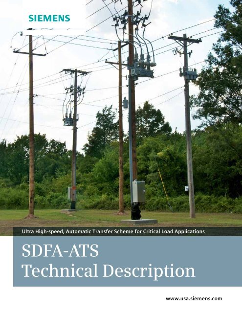
Ultra High-speed, Automatic Transfer Scheme for Critical Load Applications<br />
<strong>SDFA</strong>-<strong>ATS</strong><br />
<strong>Technical</strong> <strong>Description</strong><br />
www.usa.siemens.com
Type SDR Recloser 7SC80 Automation Controller 7SJ80 Automation Controller<br />
<strong>Siemens</strong> Distribution Feeder Automation (<strong>SDFA</strong>) system is a<br />
decentralized, distribution automation (DA) solution where all of<br />
the control and switching logic resides in automation controllers<br />
installed in distribution network reclosers and switches.<br />
The <strong>Siemens</strong> Distribution Feeder Automation (<strong>SDFA</strong>) application<br />
suite comprises a number of DA applications and solutions. <strong>SDFA</strong>-<br />
<strong>ATS</strong> (Automatic Transfer Scheme) is one such application. <strong>SDFA</strong>-<br />
<strong>ATS</strong> is an ultra high-speed, Automatic Transfer Scheme (<strong>ATS</strong>) that<br />
switches critical loads from primary to alternative power sources<br />
in as little as 100 milliseconds.<br />
<strong>SDFA</strong>-<strong>ATS</strong> protects critical loads such as medical facilities, fire<br />
stations and military installations by automatically transferring<br />
power from primary to alternative power sources in the event<br />
of a fault. When operations return to normal, the system<br />
can be programmed to automatically return the loads to the<br />
preferred sources.<br />
Transfer times depend largely on the operational speeds of the<br />
communications system and the primary line switching devices.<br />
When a <strong>Siemens</strong> type SDR recloser is used with a fiber optic<br />
communication system, transfer times of less than 100<br />
milliseconds are typical. With a WiMAX communications system,<br />
transfer times of approximately 200 milliseconds can be achieved.<br />
In it simplest form, the <strong>Siemens</strong> Distribution Feeder Automation<br />
(<strong>SDFA</strong>) system consists of automation controllers and some form<br />
of high-speed, IP-based communications link. <strong>SDFA</strong> supports<br />
brownfield as well as greenfield applications. In brownfield<br />
applications, <strong>SDFA</strong> automation controllers are interoperable with<br />
and can be installed in other manufacturers’ switchgear, and are<br />
also compatible with existing recloser or feeder<br />
protection systems.<br />
<strong>SDFA</strong>-<strong>ATS</strong> is available as loose components or as a complete<br />
package consisting of a <strong>Siemens</strong> <strong>SDFA</strong> automation controller and<br />
a <strong>Siemens</strong> type SDR recloser acting as the primary switch device.<br />
This option provides both high-speed transfer capability as well as<br />
basic feeder protection.<br />
The system can also be ordered to retrofit existing reclosers,<br />
motorized switches and circuit breakers.<br />
Features:<br />
• Rapid operation minimizes outage times<br />
• High-speed transfer (within six cycles)<br />
• Normal transfer (within nine cycles)<br />
• Protection fault supervision<br />
• Auto restoration<br />
• Manual restoration<br />
• Open or closed transition<br />
• Synchronization check<br />
• Non-proprietary, IEC 61850-<br />
compliant communications<br />
• DNP3 serial SCADA interface<br />
• Automatic or manual control<br />
• Simulation mode for realistic, off-line<br />
configuration, testing and analysis<br />
• Live test mode for on-line performance<br />
testing and verification<br />
• Supplied, pre-programmed components labtested<br />
to ensure proper operation<br />
2
How <strong>SDFA</strong>-<strong>ATS</strong> works<br />
To accomplish source transfers, <strong>Siemens</strong> SIPROTEC automation<br />
controllers govern the operation of automated reclosers situated<br />
on each side of the critical load. When a loss-of-source is detected<br />
by a controller, the recloser on the faulted side opens while the<br />
recloser on the viable side closes to maintain power to the load.<br />
Each controller contains a powerful programmable logic<br />
controller (PLC) comprising multiple AND gates that perform<br />
switching steps, which when combined, create logical sequences<br />
that control the source transfer process.<br />
Sequences can be configured to operate the reclosers in response<br />
to local and network conditions. Operating modes, threshold<br />
parameters and sequences are pre-programmed using the<br />
Windows-based <strong>Siemens</strong> DIGSI software tool. Thus, the source<br />
transfer system offers the flexibility needed to meet a wide<br />
variety of operational demands.<br />
Because the automation controllers communicate with each other<br />
in a peer-to-peer fashion, they operate autonomously with no<br />
need for master control. However, operations can be monitored,<br />
altered and controlled through an automation controller operator<br />
interface or a SCADA network via an optional DNP3 link.<br />
Loss-of-source detection<br />
Loss-of-source detection is achieved using voltage sensing inputs<br />
located within each automation controller. The sensors are<br />
connected to voltage dividers situated on the source side of the<br />
line, and when a predefined undervoltage condition is detected,<br />
the controllers immediately invoke logical sequences to initiate a<br />
source transfer process. Loss-of-source detection is supervised by<br />
overcurrent fault detectors to ensure that neither fleeting nor<br />
downstream faults will cause spurious, unneeded or unwanted<br />
source transfers.<br />
Basic topology<br />
The basic <strong>SDFA</strong>-<strong>ATS</strong> consists of the component group shown in<br />
Fig. 1. One group is required on each side of the critical load. The<br />
automation controller manages both recloser and automation<br />
functions. Fig. 2 shows a component grouping that includes a<br />
Three-Phase<br />
Source<br />
<strong>Siemens</strong> 7SC80<br />
Controller<br />
Recloser<br />
Internal<br />
Voltage Dividers<br />
Voltage<br />
Inputs<br />
Binary<br />
52 Inputs<br />
52 Contacts<br />
Current<br />
Transformers<br />
Current<br />
Inputs<br />
Binary<br />
Output<br />
Binary<br />
Output<br />
Trip<br />
Input<br />
Close<br />
Input<br />
52 Contacts<br />
Fig. 1. <strong>SDFA</strong>-<strong>ATS</strong> basic component group<br />
Critical<br />
Load<br />
Three-Phase<br />
Source<br />
<strong>Siemens</strong> 7SJ80<br />
Automation Controller<br />
Current<br />
Transformers<br />
52 Contacts<br />
External<br />
Voltage Dividers<br />
Internal<br />
Voltage Dividers<br />
<strong>Siemens</strong> 7SR224<br />
Recloser Controller<br />
Current<br />
Inputs<br />
Voltage<br />
Inputs<br />
Current<br />
Outputs<br />
Binary<br />
Outputs<br />
Voltage<br />
Inputs<br />
Current<br />
Inputs<br />
Binary<br />
Inputs<br />
Binary<br />
52 Inputs<br />
Binary<br />
Output<br />
Binary<br />
Output<br />
52 Contacts<br />
Trip<br />
Input<br />
Close<br />
Input<br />
Recloser<br />
Critical<br />
Load<br />
Fig. 2. Basic component group with separate recloser controller<br />
3
separate recloser controller. In this configuration, the automation controller handles<br />
only automation tasks. Both configurations use the voltage dividers to provide<br />
reference voltages for the loss-of-source detection tasks. A basic component group<br />
installation is shown in Fig. 3.<br />
Fig. 4 identifies the primary connections to a <strong>Siemens</strong> SDR recloser.<br />
When ordered with the type SDR recloser, the controllers are delivered within the<br />
recloser control cabinet (Fig. 5). Otherwise, the automation controller and related<br />
components are housed in a small, weatherproof cabinet designed for pole mounting.<br />
For reference purposes, reclosers are referred to as being either “own” or “external.”<br />
The recloser at which automatic or manual operations are controlled, observed or<br />
initiated using its associated controller is known at the own recloser at that<br />
controller. The remaining or distant recloser is known as the external recloser.<br />
External<br />
Voltage<br />
Sensor for<br />
25 Sync<br />
Check<br />
Load Connection<br />
Primary<br />
Contacts<br />
Internal<br />
Current<br />
Transformer<br />
Source<br />
Connection<br />
Internal<br />
Voltage<br />
Sensor<br />
Lightning<br />
Arrester<br />
Fig. 3. Basic component group installation<br />
Fig. 4. SDR recloser primary connections<br />
Recloser<br />
Source 1<br />
Recloser<br />
Source 2<br />
Transformer<br />
Auxiliary AC<br />
Supply<br />
Recloser<br />
Control Cabinet<br />
Recloser<br />
Control Cabinet<br />
Fig. 5. <strong>SDFA</strong>-<strong>ATS</strong> equipment installation<br />
4
<strong>Siemens</strong> type SDR<br />
Recloser<br />
<strong>Siemens</strong> type SDR<br />
Recloser<br />
Existing<br />
Recloser<br />
115021575 cropped<br />
<strong>Siemens</strong><br />
type 7SC80<br />
Automation/<br />
Protection<br />
Controller<br />
<strong>Siemens</strong><br />
type 7SR224<br />
Recloser<br />
Controller<br />
<strong>Siemens</strong><br />
type 7SJ80<br />
Automation<br />
Controller<br />
Existing<br />
Recloser<br />
Controller<br />
<strong>Siemens</strong><br />
type 7SC80<br />
Automation<br />
Controller<br />
Option 1:<br />
Source Transfer +<br />
Feeder Protection,<br />
<strong>Siemens</strong> Equipment<br />
Option 2:<br />
Source Transfer,<br />
<strong>Siemens</strong> Equipment<br />
Fig. 6. <strong>SDFA</strong>-<strong>ATS</strong> configuration options<br />
Option 3:<br />
Source Transfer,<br />
Existing Recloser<br />
Configuration options<br />
<strong>SDFA</strong>-<strong>ATS</strong> can be delivered complete with <strong>Siemens</strong> equipment or<br />
retrofitted to work with existing reclosers (Fig. 6).<br />
Option 1:<br />
Source transfer + feeder protection using <strong>Siemens</strong> equipment<br />
Option 1 provides the source transfer function plus traditional<br />
feeder protection using a new <strong>Siemens</strong> type SDR recloser and a<br />
7SC80 automation and protection controller. Undervoltage time<br />
and level parameters for the source transfer function can be set<br />
at the controller by the user. For protection functionality, time<br />
and level parameters for voltage, current and frequency can also<br />
be set. The controller is delivered as part of the SDR recloser<br />
control cabinet. The interconnecting cabling shown in the figure<br />
is supplied with the system.<br />
Option 2:<br />
Source transfer using <strong>Siemens</strong> equipment<br />
Option 2 provides the source transfer function using a new<br />
<strong>Siemens</strong> type SDR recloser, type 7SR224 recloser controller and<br />
7SJ80 automation controller. Undervoltage time and level<br />
parameters for the source transfer function can be set at the<br />
automation controller by the user. The controllers are delivered as<br />
part of the SDR recloser control cabinet. The interconnecting<br />
cabling shown in the figure is supplied with the system.<br />
Option 3:<br />
Source transfer using existing recloser equipment<br />
Option 3 provides the source transfer function using a new<br />
<strong>Siemens</strong> 7SC80 automation controller working in conjunction<br />
with an existing recloser and its related controller. Undervoltage<br />
time and level parameters for the source transfer function can be<br />
set by the user. The automation controller is delivered in a small,<br />
weatherproof control cabinet designed for pole mounting. The<br />
cable interconnecting the automation controller and existing<br />
recloser controller is supplied as part of the system.<br />
5
System interconnections<br />
The equipment interconnections for configuration option 1 are<br />
shown in Fig 7. This setup links a <strong>Siemens</strong> type SDR recloser to a<br />
<strong>Siemens</strong> 7SC80 automation and protection controller. Fig. 8<br />
shows the same setup with an optional sync check capability for<br />
closed transition mode operations.<br />
Fig. 7. System interconnections for configuration option 1, <strong>Siemens</strong> 7SC80 automation<br />
and protection controller linked to a <strong>Siemens</strong> type SDR recloser.<br />
Fig. 8. System interconnections for configuration option 1 with sync check capability<br />
6
Fig. 9 shows the interconnections for configuration options 2 and<br />
3. This setup interconnects a recloser and its associated controller<br />
with a <strong>Siemens</strong> automation controller (a 7SJ80 is shown). Fig. 10<br />
shows the same setup with an optional sync check capability for<br />
closed transition mode operations.<br />
Fig. 9. System interconnections for configuration options 2 and 3, <strong>Siemens</strong> 7SJ80 automation controller<br />
with separate recloser controller<br />
Fig. 10. System interconnections for configuration options 2 and 3 with sync check capability<br />
7
Communications<br />
<strong>SDFA</strong>-<strong>ATS</strong> employs the IEC 61850 communication protocol for all<br />
operational and non-operational data exchange between the<br />
automation controllers, and in systems equipped with a SCADA<br />
network interface, between the controllers and an Ethernet<br />
switching arrangement (Fig. 11). GOOSE messaging is used to<br />
obtain maximum communications speed and security.<br />
To maximize system operating speeds, <strong>Siemens</strong> recommends the<br />
use of direct fiber optic cable to interconnect the controllers. It is<br />
permissible to use alternative media including metallic cable and<br />
wireless links (such as WiMAX and Wi-Fi); however, these<br />
approaches could introduce propagation delays and network<br />
latencies that degrade system performance. The controllers<br />
contain a flexible communication port that can be configured to<br />
interface with most standard communication schemes and protocols.<br />
The optional SCADA network interface for configuration option 2<br />
consists of an Ethernet switch and an IEC 61850/DNP3 protocol<br />
converter for linking to a SCADA remote terminal unit (RTU)<br />
through a simple connection. Options 1 and 3 do not require the<br />
Ethernet switching arrangement. To facilitate conversion tasks, a<br />
comprehensive mapping file identifying gateway points, input/<br />
output types, device names and MMS functional tags for IEC<br />
61850–DNP3 translation is provided.<br />
Power supply<br />
The automation controllers delivered with the <strong>SDFA</strong>-<strong>ATS</strong> can be<br />
powered by either 115 or 230 Vac at 60 Hz, or by a direct current<br />
supply in the range of 60 to 250 volts. However, to provide<br />
continuous, reliable power from a battery source, the <strong>SDFA</strong>-<strong>ATS</strong> is<br />
designed to operate from either 24 or 48 Vdc.<br />
The 7SC80 controller contains a battery monitoring and charging<br />
system that can be set up for 24 or 48 Vdc operation. When the<br />
controller is used in configuration option 1, the controller<br />
monitors and charges the batteries, which are collocated with the<br />
controller inside the recloser control cabinet. When used in<br />
configuration option 3, the controller can be powered by the existing<br />
recloser controller supply, or set up to work with its own batteries<br />
included as part of the automation controller equipment cabinet.<br />
For systems using the 7SJ80 automation controller (configuration<br />
option 2), the controller is powered by the same battery supply as<br />
that feeding the 7SR224 recloser controller. The supply can be set<br />
up for either 24 or 48 Vdc operation. The battery monitoring and<br />
charging system is supplied as part of the recloser controller.<br />
Source 1<br />
Recloser<br />
Critical Load Recloser<br />
Source 2<br />
System Option 1<br />
<strong>Siemens</strong> type 7SC80<br />
Automation & Recloser<br />
Controller<br />
System Option 2<br />
<strong>Siemens</strong> type 7SR224<br />
Recloser Controller<br />
<strong>Siemens</strong> type 7SJ80<br />
Automation Controller<br />
SOURCE TRANSFER SYSTEM<br />
Alternative Connection<br />
Kalkitech<br />
SYNC 2000<br />
Protocol Converter<br />
(IEC 61850/DNP3)<br />
RuggedCom RS910<br />
Ethernet Switch<br />
SCADA Network<br />
OPTIONAL SCADA INTERFACE<br />
Interconnections Legend:<br />
Distribution Feeder<br />
Recloser Control Cable<br />
IEC 61850 Direct Fiber<br />
Cat 5 Ethernet<br />
DNP3 Serial<br />
Fig. 11. System communications showing system configuration options 1 and 2 linked to an optional<br />
SCADA network interface. The approach used for option 3 varies according to the communication<br />
requirements of the existing recloser equipment.<br />
8
Operator interface<br />
The human-machine interface (HMI) for the 7SC80 automation<br />
controller used in configuration options 1 and 3 is shown in Fig.<br />
12. The interface consists of virtual pushbuttons, labeling, status<br />
indicators and an operator display and is accessible via the web<br />
through a personal computer. Pushbuttons are operated using a<br />
“point-and-click” approach and can be assigned by the utility to<br />
perform desired tasks. Control and indicator labeling is<br />
automatically generated and displayed at the appropriate<br />
locations on the screen.<br />
The HMI allows an operator to supervise, control, and monitor the<br />
<strong>SDFA</strong>-<strong>ATS</strong> at any point where a personal computer and Web<br />
access are available. The status indicators show the functional<br />
status of the <strong>SDFA</strong>-<strong>ATS</strong>, the automation controller and its related<br />
battery supply. The control pushbuttons can be used to open and<br />
close the own recloser, apply and release hot line tags, reset<br />
lockouts, acknowledge system conditions and alarms, change<br />
operating modes, initiate system actions, and disable the controls<br />
to prevent accidental operations. The operator display enables<br />
monitoring of local line voltage, current and frequency conditions<br />
and, in conjunction with the control pushbuttons, allows an<br />
operator to select and activate system functions and activities.<br />
When the automation controller is used in conjunction with an<br />
existing recloser controller as in the case of configuration option<br />
3, some control functions such as opening and closing the own<br />
recloser, applying and removing hot line tags, clearing lockouts<br />
and monitoring battery status can be performed by the recloser<br />
controller as directed by the utility.<br />
Assignable System<br />
Status Indicators<br />
Operator Display<br />
Relay Status Indicators<br />
Automatic Labeling<br />
Display<br />
Recloser Open/<br />
Close Pushbuttons<br />
Control Pushbuttons<br />
Assignable Control<br />
Pushbuttons<br />
Automatic Labeling<br />
Display<br />
Lock Pushbutton to<br />
Prevent Accidental<br />
Operations<br />
Acknowledge<br />
Pushbutton<br />
Fig. 12. Web-based, virtual operator interface for the 7SC80 automation controller as viewed on a personal computer screen<br />
9
The HMI for the 7SJ80 automation controller used in<br />
configuration option 2 is shown in Fig. 13. The interface consists<br />
of front-panel pushbuttons and a keypad, status indicators and a<br />
backlit operator display that allow an operator to supervise,<br />
control and monitor the <strong>SDFA</strong>-<strong>ATS</strong> at the recloser.<br />
The status indicators show the functional status of the <strong>SDFA</strong>-<strong>ATS</strong><br />
and the automation controller. The control pushbuttons can be<br />
used to open and close the own recloser, acknowledge system<br />
conditions and alarms, change operating modes and initiate<br />
system actions. The operator display enables monitoring of local<br />
line voltage, current and frequency conditions and, in conjunction<br />
with the control pushbuttons, allows an operator to select and<br />
activate system functions and activities.<br />
Because the automation controller is used in conjunction with a<br />
recloser controller, some control functions such as opening and<br />
closing the own recloser, applying and removing hot line tags,<br />
clearing lockouts and monitoring battery health can be performed<br />
by the recloser controller as directed by the utility.<br />
For utilities employing a SCADA network, the <strong>SDFA</strong>-<strong>ATS</strong> can be<br />
connected to an RTU to enable remote supervision, monitoring<br />
and control of the system (Fig. 11).<br />
SIEMENS<br />
Relay Status<br />
Indicators<br />
Operator Display<br />
Run<br />
Error<br />
MAIN MENU 01/05<br />
Annunciation -> 1<br />
Measurement -> 2<br />
Control -> 3<br />
Settings -> 4<br />
Esc<br />
Enter<br />
Control Pushbuttons<br />
F7 F8 F9<br />
7 8 9<br />
System Status<br />
Indicators<br />
F4 F5 F6<br />
4 5 6<br />
F1 F2 F3<br />
1 2 3<br />
Control Keypad<br />
Fn 0 .<br />
Lampcheck<br />
Pushbutton<br />
USB<br />
Programming Port<br />
SIEMENS<br />
CLOSE<br />
TRIP<br />
Recloser Close/<br />
Trip Pushbuttons<br />
7SJ8041-1EC96-1FQ1<br />
LOS<br />
Fig. 13. Front-panel operator interface for the<br />
7SJ80 automation controller<br />
10
Operating modes<br />
Through various <strong>SDFA</strong>-<strong>ATS</strong> operating modes, the transfer function<br />
can be automatically or manually initiated or blocked, and<br />
enabled, disabled, or modified as operating needs and conditions<br />
change. A full-functioned, realistic simulation mode allows the<br />
system to be programmed, configured and tested without<br />
actually operating any recloser device. A live test mode facilitates<br />
field testing for verification and commissioning purposes.<br />
Auto source-transfer mode<br />
The auto source-transfer mode enables automatic source<br />
transfers. Automatic operations are functional only when auto<br />
source-transfer mode is active, and are automatically disabled<br />
whenever there is a system communication fault, operation<br />
failure, a hot line tag is in place, or when a line fault occurs and<br />
the system is in block transfer with overcurrent pickup mode. Fig.<br />
14 shows the selection logic for auto source-transfer mode.<br />
System operating modes include:<br />
• Auto source-transfer<br />
• Normal transfer<br />
• High-speed transfer<br />
• Block transfer with overcurrent pickup<br />
• Auto restoration<br />
• Manual restoration<br />
• Open transition<br />
• Closed transition<br />
• Simulation<br />
• Live test<br />
Fig. 14. Auto source-transfer mode selection logic<br />
11
A system communication fault occurs whenever unexpected<br />
communication delays occur at an automation controller. The<br />
controllers continuously check the validity of incoming data and<br />
issue a communication fault when any unusual delays are<br />
encountered.<br />
An Own Device Operation Failure occurs whenever a controller<br />
sends a trip or close command and the associated own recloser<br />
does not respond within a specified amount of time. An External<br />
Device Operation Failure occurs when the external recloser fails<br />
to operate properly.<br />
The Hot Line Tag signal is carried between the recloser and<br />
controller through the recloser control cable. Whenever the signal<br />
is present, the activate command from the automation controller<br />
is inhibited, precluding automatic system operation. Similarly,<br />
when an External Device Hot Line Tag signal is issued by the other<br />
recloser via the direct fiber link, system operation is inhibited.<br />
Normal transfer mode<br />
Source transfers can be configured as being either high-speed or<br />
normal. When normal transfer mode is active, recloser device 2<br />
operates immediately after recloser device 1 for a total elapsed<br />
transfer time of 8.4 cycles or 140 milliseconds when a type SDR<br />
recloser is used (Fig. 15). Operational logic for the normal process<br />
is shown in Fig. 16.<br />
Fig. 15. Normal transfer mode operational sequence<br />
Fig. 16. Normal transfer mode operational logic<br />
12
High-speed transfer mode<br />
High-speed transfer mode is active whenever normal transfer<br />
mode is disabled. When high-speed transfer mode is active,<br />
recloser devices 1 and 2 operate near-simultaneously for a total<br />
elapsed transfer time of less than six cycles or 100 milliseconds<br />
when a type SDR recloser is used (Fig. 17). Operational logic for<br />
the high-speed process is shown in Fig. 18.<br />
Fig. 17. High-speed transfer mode operational sequence<br />
Fig. 18. High-speed transfer mode operational logic<br />
13
Block transfer with overcurrent pickup mode<br />
When enabled, the block transfer with overcurrent pickup mode<br />
blocks source transfers when the automation controller<br />
undervoltage and overcurrent elements pick up at the same time<br />
(Fig. 19). This condition typically occurs when a fault at or near<br />
the critical load increases the line current and collapses the feeder<br />
voltage. When such a fault occurs, the controller issues an alarm<br />
and disables auto source-transfer mode, which precludes source<br />
transfers to allow sufficient time for the feeder protection to<br />
isolate the fault.<br />
Auto restoration mode<br />
Once a preferred source has become available, the distribution<br />
feeder must be restored to its normal, default operational state.<br />
This can be done in three ways:<br />
• Automatic restoration, automatically initiated<br />
• Automatic restoration, manually initiated<br />
• Manual restoration<br />
Automatically initiated automatic restoration automatically<br />
reconfigures the feeder to its default condition. When auto<br />
Fig. 19. Block transfer with overcurrent pickup mode operational sequence<br />
14
estoration mode is active, an automation controller continuously<br />
monitors the status of both sources and issues a restore<br />
command 60 seconds after the preferred source becomes<br />
available. This approach requires no human intervention as long<br />
as auto restoration mode is enabled. When auto restoration mode<br />
is disabled, the automatic restoration sequence must be initiated<br />
by an operator.<br />
Automatic restoration mode logic is shown in Fig. 20. When both<br />
sources are active, AND gate 1 drives a 60-second timer. If after<br />
60 seconds auto restoration and auto source-transfer modes are<br />
active, a two-second long restore command is issued via the<br />
action of AND gate 2 and the OR gate.<br />
Manual restoration mode<br />
Manual restoration mode is active whenever auto restoration<br />
mode is disabled. When manual restoration mode is enabled, an<br />
operator can manually restore the feeder by directly operating<br />
each recloser from its respective automation controller operator<br />
interface or via the SCADA network.<br />
Closed transition mode<br />
Once an automatic restoration command is issued, the resulting<br />
reconfiguration can be carried out using either closed transition<br />
mode or open transition mode. When closed transition mode is<br />
active, recloser device 1 closes and then recloser device 2 opens,<br />
thus creating a momentary transition overlap between S1 and S2<br />
before S1 is connected to the critical load (Fig. 21). Closed<br />
transition mode operational logic is shown in Fig. 22.<br />
The system is capable of performing a synchronization check<br />
following a closed transition when it is wired to sample the same<br />
phase voltage on the source and load sides of the recloser (Fig. 8<br />
or 10) and when necessary logic and settings are implemented in<br />
the automation controller. Use of a sync-check function will<br />
increase operational delays on close commands and in the case of<br />
configuration option 2, will limit loss-of-source detection to a<br />
single phase.<br />
Fig. 20. Automatic restoration mode operational logic<br />
Fig. 21. Closed transition mode operational sequence<br />
15
Open transition mode<br />
Open transition mode is active whenever closed transition mode<br />
is disabled. When open transition mode is active, recloser device<br />
2 opens followed by recloser device 1, thus creating a momentary<br />
break between S1 and S2 before S1 is connected to the critical<br />
load (Fig. 24). Open transition mode operational logic is shown<br />
in Fig. 23.<br />
Fig. 22. Closed transition mode operational logic<br />
Fig. 23. Open transition mode operational logic<br />
Fig. 24. Open transition mode operational sequence<br />
16
Simulation mode<br />
For test and analysis purposes, simulation mode allows the<br />
operator to simulate switching sequences without actually<br />
operating any reclosers. Once enabled, source on/off conditions<br />
can be simulated to initiate sequences. If during simulation a true<br />
loss-of-source is detected, the controller will automatically disable<br />
simulation and initiate an actual transfer sequence.<br />
Once event files have been downloaded, system performance can<br />
be analyzed using <strong>Siemens</strong> SIGRA analytical software (Fig. 26)<br />
and other standard tools (Fig. 25). Both binary and analogue data<br />
is stored for the various operating modes, recloser operations and<br />
source performance.<br />
Live test<br />
For test and commissioning purposes, live test mode provides an<br />
effective means to verify actual system performance in the field.<br />
Use of the mode eliminates the need to disconnect and reconnect<br />
wiring, and when used in conjunction with the SIGRA analysis<br />
software tool (Fig. 26), an accurate picture of system<br />
performance can be formed by analyzing the fault records stored<br />
within each automation controller.<br />
Fault recording<br />
Whenever any loss-of-source or restoration operations occur,<br />
either during actual or simulated operations, the automation<br />
controller stores a 1.5-second-long oscillographic fault recording<br />
of each event. For test and analysis purposes, recent event data<br />
can be downloaded using the <strong>Siemens</strong> DIGSI software tool.<br />
To ensure accurate time stamping for system events, the clocks in<br />
the automation controllers are synchronized by Network Time<br />
Protocol data carried over the fiber optic cable linking the<br />
controllers. For systems using wireless links, an optional GPS<br />
module available with the 7SC80 controller can be used to<br />
provide synchronized time-stamping capabilities.<br />
Fig. 25. System performance test results<br />
Fig. 26. SIGRA analysis screen<br />
17
Flexible implementation<br />
<strong>SDFA</strong>-<strong>ATS</strong> can be delivered with all required hardware and<br />
software for immediate implementation or designed to retrofit<br />
with existing equipment. The use of reclosers instead of<br />
motorized switches will result in maximum system operating<br />
speeds and preserve full feeder protection capabilities.<br />
For utilities needing only to protect a critical load, configuration<br />
option 2 (Fig. 6) offers maximum economy, effective<br />
performance and rapid rollout. This option can be implemented<br />
within one month after receipt of order and provides customers<br />
with immediate benefit. When the system is outfitted with<br />
reclosers, outages often last less than 100 milliseconds, which<br />
means they go unnoticed by even the most demanding<br />
consumers.<br />
Configuration option 1 offers the same benefits as option 2 and<br />
provides traditional feeder protection functionality. This option is<br />
ideal for new installations or for utilities considering replacement<br />
of obsolete or aging recloser equipment.<br />
Configuration option 3 is intended for utilities looking to make<br />
incremental improvements to their existing distribution systems<br />
or to safeguard previous investments. <strong>Siemens</strong> engineers can<br />
work with existing equipment of any make to design a<br />
successful retrofit.<br />
To help ensure a problem-free deployment, the automation<br />
controller and other <strong>Siemens</strong> equipment supplied with the system<br />
are completely configured and tested in the <strong>Siemens</strong> Smart Grid<br />
laboratory in Wendell, N.C., (Fig. 27). Furthermore, <strong>Siemens</strong><br />
offers a full range of system support products and services,<br />
including on-site and factory support, testing and analysis,<br />
accessories, training, and product documentation.<br />
Fig. 27. Recloser and circuit breaker undergoing test at the<br />
<strong>Siemens</strong> Smart Grid laboratory, Wendell, N.C., USA.<br />
Find out more today!<br />
To discover how <strong>SDFA</strong>-<strong>ATS</strong> can help maximize your<br />
distribution feeder availability, please contact your<br />
nearest <strong>Siemens</strong> representative. We’ll be pleased<br />
to discuss your specific needs and offer a solution<br />
that will increase customer satisfaction and reduce<br />
service costs.<br />
18
Notes:<br />
19
<strong>Siemens</strong> Industry, Inc.<br />
7000 <strong>Siemens</strong> Road<br />
Wendell, NC 27591<br />
1-888-597-2566<br />
smartgrid.energy@siemens.com<br />
Printed in USA | www.usa.siemens.com/smartgrid<br />
Subject to change without prior notice | All rights reserved<br />
Order no.: IC1000-E220-A142-X-4AUS | © 2012 <strong>Siemens</strong> Industry, Inc.<br />
The information provided in this brochure contains merely general descriptions<br />
or characteristics of performance which in case of actual use do no t always<br />
apply as described or which may change as a result of further development of<br />
the products. An obligation to provide the respective characteristics shall only<br />
exist if expressly agreed in the terms of contract.<br />
All product designations may be trademarks or product names of <strong>Siemens</strong> AG<br />
or supplier companies whose use by third parties for their own purposes could<br />
violate the rights of the owners.