The Jumper Settings of FBs-6AD Analogue Input Module - FATEK
The Jumper Settings of FBs-6AD Analogue Input Module - FATEK
The Jumper Settings of FBs-6AD Analogue Input Module - FATEK

You also want an ePaper? Increase the reach of your titles
YUMPU automatically turns print PDFs into web optimized ePapers that Google loves.
<strong>The</strong> <strong>Jumper</strong> <strong>Settings</strong> <strong>of</strong> <strong>FBs</strong>-<strong>6AD</strong> <strong>Analogue</strong> <strong>Input</strong> <strong>Module</strong><br />
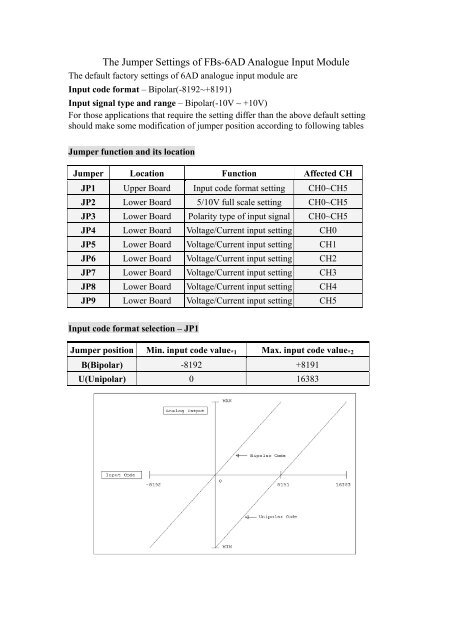
<strong>The</strong> default factory settings <strong>of</strong> <strong>6AD</strong> analogue input module are<br />
<strong>Input</strong> code format – Bipolar(-8192~+8191)<br />
<strong>Input</strong> signal type and range – Bipolar(-10V ~ +10V)<br />
For those applications that require the setting differ than the above default setting<br />
should make some modification <strong>of</strong> jumper position according to following tables<br />
<strong>Jumper</strong> function and its location<br />
<strong>Jumper</strong> Location Function Affected CH<br />
JP1 Upper Board <strong>Input</strong> code format setting CH0~CH5<br />
JP2 Lower Board 5/10V full scale setting CH0~CH5<br />
JP3 Lower Board Polarity type <strong>of</strong> input signal CH0~CH5<br />
JP4 Lower Board Voltage/Current input setting CH0<br />
JP5 Lower Board Voltage/Current input setting CH1<br />
JP6 Lower Board Voltage/Current input setting CH2<br />
JP7 Lower Board Voltage/Current input setting CH3<br />
JP8 Lower Board Voltage/Current input setting CH4<br />
JP9 Lower Board Voltage/Current input setting CH5<br />
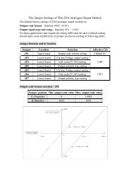
<strong>Input</strong> code format selection – JP1<br />
<strong>Jumper</strong> position Min. input code value *1 Max. input code value *2<br />
B(Bipolar) -8192 +8191<br />
U(Unipolar) 0 16383
<strong>The</strong> MAX and MIN value in the vertical axis(analog input) represent the respective<br />
maximum and minimal input signal for a specific type. For example, if the input<br />
signal range set to –5V~+5V<br />
* 1 – This value will be obtained when the input signal is –5V<br />
* 2 – This value will be obtained when the input signal is +5V<br />
<strong>The</strong> value shown above is the raw 14-bit input value read by CPU, the actual value<br />
read by application is depends on the I/O configuration setting(Set by Winproladder<br />
s<strong>of</strong>tware)<br />
<strong>Input</strong> signal range and polarity setting – JP2,JP3<br />
<strong>Jumper</strong> Location Signal source type *3<br />
JP2 JP3 Voltage Current<br />
5V B -5V~+5V -10 mA ~ +10 mA<br />
10V B -10V~+10V -20 mA ~ +20 mA<br />
5V U 0V ~ +5V 0 ~ +10 mA<br />
10V U 0V ~ +10V 0 ~ +20 mA<br />
* 3 – Each channel can be individually set for voltage or current type signal.<br />
Current or Voltage type input signal selection- JP4~JP9<br />
<strong>Jumper</strong> Position<br />
Signal Type<br />
V<br />
Voltage<br />
I<br />
Current<br />
<strong>Input</strong> Channel<br />
CH0<br />
CH1<br />
CH2<br />
CH3<br />
CH4<br />
CH5<br />
<strong>Jumper</strong><br />
JP4<br />
JP5<br />
JP6<br />
JP7<br />
JP8<br />
JP9