U6000AT+ Operator's Manual - CETAC Technologies
U6000AT+ Operator's Manual - CETAC Technologies
U6000AT+ Operator's Manual - CETAC Technologies

You also want an ePaper? Increase the reach of your titles
YUMPU automatically turns print PDFs into web optimized ePapers that Google loves.
U-6000AT + Ultrasonic Nebulizer /<br />
Membrane Desolvator Operator’s<br />
<strong>Manual</strong>
Product Warranty Statement<br />
SD Acquisition, Inc., DBA <strong>CETAC</strong> <strong>Technologies</strong> (“<strong>CETAC</strong>”), warrants<br />
any <strong>CETAC</strong> unit manufactured or supplied by <strong>CETAC</strong> for a period<br />
beginning on the date of shipment and ending on the sooner to occur of:<br />
(a) the date that is twelve (12) months from the date of installation, or<br />
(b) the date that is thirteen (13) months from the date of shipment.<br />
Units found in the reasonable judgement of <strong>CETAC</strong> to be defective in<br />
material or workmanship will be repaired or replaced by <strong>CETAC</strong><br />
without charge for parts and labor. <strong>CETAC</strong> reserves the right to<br />
change or improve the design of any unit without assuming any<br />
obligation to modify any unit previously manufactured.<br />
This warranty does not cover any unit that has been subject to misuse,<br />
neglect, negligence, or accident. The warranty does not apply to any<br />
damage to the unit that is the result of improper installation or<br />
maintenance, or to any unit that has been operated or maintained in<br />
any way contrary to the instructions specified in the <strong>CETAC</strong><br />
instruction and operation manual. Operation of the <strong>CETAC</strong> unit inside<br />
a laboratory fume hood is contra-indicated and will void the warranty.<br />
Any attempt to repair or alter any <strong>CETAC</strong> unit by anyone other than<br />
by <strong>CETAC</strong> authorized personnel or agents will void this warranty. If<br />
any non-<strong>CETAC</strong> component is installed in the <strong>CETAC</strong> manufactured<br />
unit without the approval of <strong>CETAC</strong>, the warranty will be voided. In<br />
addition, this warranty does not extend to repairs made necessary by<br />
the use of parts, accessories or fluids which are either incompatible<br />
with the unit or adversely affect its operation, performance or<br />
durability. <strong>CETAC</strong>’S obligation under this warranty is strictly and<br />
exclusively limited to repair or replacement of defective <strong>CETAC</strong> parts,<br />
and no claim of breach of warranty shall be cause for cancellation or<br />
recission of the contract of sale of any unit.<br />
The foregoing express warranty is in lieu of all other warranties,<br />
expressed or implied, including warranties of merchantability and<br />
fitness for a particular purpose. <strong>CETAC</strong> shall not be bound by any<br />
representations or statements on the part of its employees or agents<br />
whether oral or in writing and including any made in catalogues and<br />
other promotional material including technical details and<br />
specifications except where such representations and statements are<br />
expressly made part of this contract. <strong>CETAC</strong> assumes no responsibility<br />
for incidental, consequential or other damages, even if advised of such a<br />
possibility, including but not limited to loss or damage of property, loss<br />
of revenue, loss of use of the unit, loss of time, or inconvenience.<br />
<strong>CETAC</strong>’s liability<br />
on any claim for loss or damage arising out of the sale, resale or use of<br />
any of its products shall in no event exceed the selling price of the unit.
Purchaser shall indemnify <strong>CETAC</strong> against any claim or liability which<br />
may be asserted as relates to the following: (i) the use to which any<br />
product supplied hereunder is put infringes the patent, copyright or<br />
other intellectual property rights of any third party; or (ii) any liability<br />
resulting from the failure by Purchaser to observe the terms of this<br />
Warranty.<br />
Returned Product Procedures<br />
Claims for shipment damage (evident or concealed) must be filed with<br />
the carrier by the buyer. <strong>CETAC</strong> must be notified within ninety (90)<br />
days of shipment of incorrect materials. No product may be returned,<br />
whether in warranty or out of warranty, without first obtaining<br />
approval from <strong>CETAC</strong>. No replacements will be provided nor repairs<br />
made for products returned without such approval. Any returned<br />
product must be accompanied by a return authorization number. The<br />
expense of returning the unit to <strong>CETAC</strong> for service will be paid by the<br />
buyer. The status of any product returned later than thirty (30) days<br />
after issuance of a return authorization number will be subject to<br />
review. Shipment of repaired products will generally be made forty<br />
eight (48) hours after the receipt.<br />
Products may not be returned which are contaminated by radioactive<br />
materials, infectious agents, or other materials constituting health<br />
hazards to <strong>CETAC</strong> employees.<br />
Returned Product Warranty Determination<br />
After <strong>CETAC</strong>’S examination, warranty or out of warranty status will be<br />
determined. If a warranted defect exists, the product will be repaired<br />
at no charge and shipped prepaid back to the buyer. If the buyer<br />
desires an air freight return, the product will be shipped collect.<br />
Warranty repairs do not extend the original warranty period.<br />
If an out of warranty defect exists, the buyer shall be notified of the<br />
repair cost. At such time the buyer must issue a valid purchase order<br />
to cover the cost of repair and freight, or authorize the products to be<br />
shipped back as is, at the buyer’s expense. Failure to obtain a purchase<br />
order number approval within fifteen (15) days of notification will<br />
result in the products being returned as is, at the buyers expense.
COPYRIGHT<br />
Copyright SD Acquisition, Inc., DBA<br />
<strong>CETAC</strong> <strong>Technologies</strong><br />
480026 Version 1.2, June, 2004<br />
REPRODUCTION<br />
All rights reserved. Reproduction or<br />
transmission of this document in whole or<br />
in part, and by any means without the<br />
express written consent of the copyright<br />
owner or authorized agent is prohibited.<br />
Requests for additional copies of this, or<br />
any other <strong>CETAC</strong> publication, can be filled<br />
by contacting an authorized distributor or<br />
<strong>CETAC</strong> <strong>Technologies</strong><br />
Customer Service & Support<br />
14306 Industrial Road<br />
Omaha, Nebraska 68144, USA<br />
Phone (800) 369-2822 (USA only)<br />
Phone (402) 733-2829<br />
Fax (402) 733-1932<br />
E-mail custserv@cetac.com<br />
DISCLOSURE<br />
This document contains <strong>CETAC</strong><br />
proprietary data and is provided solely to<br />
its customers for their express benefit of<br />
safe, efficient operation and maintenance<br />
of the product described herein. Use or<br />
disclosure of <strong>CETAC</strong> proprietary data for<br />
the purpose of manufacture or<br />
reproduction of the item described herein,<br />
or any similar item, is prohibited, and<br />
delivery of this document shall not<br />
constitute any license or implied<br />
authorization to do so.<br />
REVISIONS<br />
<strong>CETAC</strong> <strong>Technologies</strong> strives to provide the<br />
scientific community with an unparalleled<br />
combination of effective technology and<br />
continuing value. Modular upgrades for<br />
existing instruments will continue to be a<br />
prime consideration as designs progress.<br />
<strong>CETAC</strong> <strong>Technologies</strong> reserves the right to<br />
revise this document and/or improve<br />
products described herein at any time<br />
without notice or obligation. Warranty<br />
registration entitles the named owner<br />
exclusively to manual change pages/new<br />
editions as they are published.<br />
SAFETY<br />
Instruments, accessories, components or<br />
other associated materials may not be<br />
returned to <strong>CETAC</strong> <strong>Technologies</strong> if<br />
contaminated with biohazard or<br />
radioactive materials, infectious agents, or<br />
any other materials and/or conditions that<br />
could constitute a health or injury hazard<br />
to <strong>CETAC</strong> employees. Call Customer<br />
Service and Support if there is any<br />
question or doubt relative to<br />
decontamination requirements. CAUTION<br />
and WARNING statements, as applied in<br />
this document, shall be interpreted<br />
consistent with the following context:<br />
CAUTION applies only to potential<br />
property damage conditions; WARNING<br />
applies to potential personal injury<br />
conditions, in combination with or<br />
exclusive of potential property damage.<br />
All user-serviceable components are<br />
specifically identified in this document as<br />
such; the balance shall be assumed to<br />
require the expertise of a factory service<br />
technician/engineer for adjustment, repair,<br />
replacement, modification, etc. Others not<br />
so qualified and performing these actions<br />
shall do so at their own risk. Furthermore,<br />
never operate the instrument without first<br />
reading and understanding the U-6000AT +<br />
Ultrasonic Nebulizer / Membrane<br />
Desolvator Operator’s <strong>Manual</strong>, and<br />
ensuring that it is operated safely and<br />
properly.<br />
ORIGINAL PACKAGING<br />
Retain original factory packaging for<br />
moves and factory return shipments.<br />
Shipping in anything other than the<br />
original fitted foam and container can<br />
result in incidental damage from which the<br />
purchaser will not be protected under<br />
warranty.<br />
WARNING<br />
Under all conditions the user must observe safe laboratory<br />
procedures during the operation of this product.
Operator’s <strong>Manual</strong> Addendum<br />
Notices and Compliance Declarations<br />
FEDERAL COMMUNICATIONS<br />
COMMISSION (FCC) NOTICE<br />
This equipment has been tested and found<br />
to comply with the limits for a Class A<br />
digital device, pursuant to Part 15 of the<br />
FCC Rules. These limits are designed to<br />
provide reasonable protection against<br />
harmful interference in a commercial<br />
installation.<br />
This equipment generates, uses, and can<br />
radiate radio frequency energy and, if not<br />
installed and used in accordance with the<br />
instructions, may cause harmful<br />
interference to radio communications.<br />
Operation of this equipment in a<br />
residential environment is likely to cause<br />
harmful interference, in which case the<br />
user will be required to correct the<br />
interference at his own expense.<br />
CANADIAN NOTICE<br />
This digital apparatus does not exceed the<br />
Class A limits for radio noise emissions<br />
from digital apparatus as set out in the<br />
interference-causing equipment standard<br />
entitled "Digital Apparatus." ICES-003 of<br />
the Department of Communications.<br />
AVIS CANADIEN<br />
Cet appareil numerique respecte les<br />
limites de bruits radioelectriques<br />
applicables aux appareils numeriques de<br />
Classe A prescrites dans la norme sur le<br />
materiel brouilleur: "Appareils<br />
Numeriques," NMB-003 edictee par le<br />
ministre des Communications.<br />
MODIFICATIONS<br />
The FCC requires the user to be notified<br />
that any changes or modifications made to<br />
this device that are not expressly approved<br />
by <strong>CETAC</strong> <strong>Technologies</strong>, Inc. may void the<br />
user's authority to operate the equipment.<br />
CABLES<br />
Connections to this device must be made<br />
with shielded cables with metallic RFI/EMI<br />
connector hoods to maintain compliance<br />
with FCC Rules and Regulations.<br />
AD-1
Operator’s <strong>Manual</strong> Addendum<br />
Notices and Compliance Declarations<br />
POWER CORD SET REQUIREMENTS<br />
The power cord set supplied with your<br />
instrument meets the requirements of the<br />
country where you purchased the<br />
instrument.<br />
If you use the instrument in another<br />
country, you must use a power cord set<br />
that meets the requirements of that<br />
country.<br />
WARNING<br />
This equipment is designed for connection to a grounded (earthed) outlet. The<br />
grounding type plug is an important safety feature. To reduce the risk of electrical<br />
shock or damage to the instrument, do not disable this feature.<br />
CAUTION<br />
To reduce the risk of fire hazard and electrical shock, do not expose the unit to rain or<br />
humidity. To reduce the risk of electrical shock, do not open the cabinet. All maintenance<br />
is to be performed by an Authorized <strong>CETAC</strong> Service Provider.<br />
Protection provided by the equipment may be impaired if the equipment is used in a<br />
manner not specified by the manufacturer.<br />
CLEANING INSTRUCTIONS<br />
To clean the exterior surfaces of the instrument, complete the following steps:<br />
1 Shut down and unplug the instrument.<br />
2 Wipe the instrument exterior surfaces<br />
only using a towel dampened with a<br />
lab-grade cleaning agent.<br />
3 Repeat step 2, using a towel dampened<br />
with clear water.<br />
4 Dry the instrument exterior using a dry<br />
towel.<br />
WARNING<br />
Do not allow any liquid to enter the instrument cabinet, or come into contact with<br />
any electrical components. The instrument must be thoroughly dry before you<br />
reconnect power, or turn the instrument on.<br />
COOLING FAN OBSTRUCTION<br />
The instrument cooling fan(s) shall remain unobstructed at all times. Do not operate the<br />
instrument if the cooling fan(s) are blocked or obstructed in any manner.<br />
ENVIRONMENTAL<br />
Operating Temperature: 10° to 30°C<br />
Relative Humidity 0% to 95%<br />
AD-2
Operator’s <strong>Manual</strong> Addendum<br />
Notices and Compliance Declarations<br />
PANNEAU NE DOIT ÊTRE ENLEVE QUE<br />
PAR UN RÉPARATEUR QUALIFIÉ.<br />
AVERTISSEMENT<br />
POUR UNE PROTECTION CONTINUÉ<br />
CONTRE LES RISQUES D’INCENDIE,<br />
REMPLACER UNIQUEMENT PAR DES<br />
FUSIBLES DE MÊME TYPE ET<br />
AMPÈRAGE.<br />
AVERTISSEMENT<br />
TOUT CONTACT AVEC LES HAUTES<br />
TENSIONS PEUT ENTRAINER LA MORT<br />
OU DES BLESSURES SÉVÈRES. CE<br />
PANNEAU NE DOIT ÊTRE ENLEVE QUE<br />
PAR UN RÉPARATEUR QUALIFIÉ.<br />
AVERTISSEMENT<br />
NE PAS GLISSER LA MAIN SOUS OU DERIERE LES<br />
ECRANS THERMIQUES DU FOUR. GARDER LA<br />
PORTE D'ACCES AU DEVANT DU BOITIER BIEN<br />
FERMEE POUR ASSURER LA PROTECTION CONTRE<br />
LES BRULURES<br />
AVERTISSEMENT<br />
TOUT CONTACT AVEC LES HAUTES<br />
TENSIONS PEUT ENTRAINER LA MORT<br />
OU DES BLESSURES SÉVÈRES. CE<br />
AVERTISSEMENT<br />
TOUT CONTACT AVEC LES HAUTES<br />
TENSIONS PEUT ENTRAINER LA MORT<br />
OU DES BLESSURES SÉVÈRES. CE<br />
PANNEAU NE DOIT ÊTRE ENLEVE QUE<br />
PAR UN RÉPARATEUR QUALIFIÉ.<br />
AD–3
Operator’s <strong>Manual</strong> Addendum<br />
Notices and Compliance Declarations<br />
AVERTISSEMENT<br />
TOUT CONTACT AVEC LES HAUTES<br />
TENSIONS PEUT ENTRAINER LA MORT<br />
OU DES BLESSURES SÉVÈRES. CE<br />
PANNEAU NE DOIT ÊTRE ENLEVE QUE<br />
PAR UN RÉPARATEUR QUALIFIÉ.<br />
WARNING<br />
HIGH LEAKAGE CURRENT -<br />
ENSURE PROPER GROUNDING<br />
AVERTISSEMENT<br />
COURANT DE FUITE ÉLEVÉ — FORNIR<br />
UNE MISE À LA TERRE EFFICACE.<br />
AVERTISSEMENT<br />
SURFACES CHAUDES, LAISSER LE<br />
COUVERCLE HERMÉTIQUEMENT<br />
FERMÉ.<br />
POUR ACCÉDER, METTRE LA<br />
TEMPÉRATURE DU FOUR À ZÉRO,<br />
OUVRIR LE COUVERCLE ET LAISSER<br />
REFROIDIR 5 MINUTES AVANT DE<br />
TOUCHER LA VERRERIE OU TOUTE<br />
SURFACE MÉTALLIQUE INTÉRIEURE.<br />
AVERTISSEMENT<br />
POUR LA PROTECTION PERMANENTE<br />
CONTRE UN CHOC ÉLECTRIQUE, UNE<br />
BRÛLURE DES YEUX (RADIATION UV)<br />
OU DE LA PEAU, LAISSER LE<br />
COUVERCLE HERMÉTIQUEMENT<br />
FERMÉ LORSQUE L’APPAREIL EST SOUS<br />
TENSION.<br />
LAISSER REFROIDIR 5 MINUTES<br />
(APPAREIL ÉTEINT) AVANT D’ENLEVER<br />
LE COUVERCLE.<br />
AD-4
Contents
Contents<br />
Preface<br />
Who Should Read This Book<br />
How to Use This Book<br />
Conventions Used in This Book<br />
Instructions<br />
Terminology<br />
Notes<br />
Cautions<br />
Warnings<br />
Where to Go for More Information<br />
xii<br />
xii<br />
xii<br />
xiii<br />
xiii<br />
xiv<br />
xiv<br />
xv<br />
xv<br />
xv<br />
1 Introduction 1–2<br />
Ultrasonic Nebulizer/Membrane Desolvator Components 1–3<br />
Optional Accessories 1–9<br />
2 Preparing for Installation 2–2<br />
Choosing a Location 2–2<br />
Space Requirements 2–2<br />
Power Requirements 2–2<br />
Unpacking the U-6000AT + 2–4<br />
ICP Requirements 2–4
U-6000AT + Ultrasonic Nebulizer / Membrane Desolvator Operator’s <strong>Manual</strong><br />
Contents<br />
3 Installing the U-6000AT + System 3–2<br />
Drainage System Assembly 3–2<br />
Liquid Sample Delivery and Rinse System 3–3<br />
Sample Inlet Tubing 3–3<br />
Sample Inlet Tubing Extension 3–6<br />
Establishing External Connections 3–6<br />
Connecting<br />
the U-6000AT + to the power source 3–7<br />
the Nebulizer Gas to the Ultrasonic Nebulizer 3–7<br />
the Ultrasonic Nebulizer to the Membrane Desolvator 3–8<br />
Additional Connections for the Analysis of<br />
Organic Solvents 3–10<br />
Connecting the Membrane Desolvator<br />
to the Analytical Instrument 3–10<br />
4 Verifying Installation 4–2<br />
Initial Operating Procedure 4–2<br />
ICP Operation 4–5<br />
System Optimization 4–5<br />
ICP-AES/Ultrasonic Nebulizer Optimization Procedure 4–6<br />
ICP-AES/U-6000AT + Optimization Procedure (organic) 4–7<br />
ICP-MS/U-6000AT + Optimization Procedure (aqueous) 4–8<br />
ICP-MS/U-6000AT + Optimization Procedure (organic) 4–9<br />
vii
U-6000AT + Ultrasonic Nebulizer / Membrane Desolvator Operator’s <strong>Manual</strong><br />
Contents<br />
5 Using the U-6000AT + Ultrasonic Nebulizer /<br />
Membrane Desolvator 5–2<br />
Establishing Optimal Conditions 5–2<br />
Creating the Lab Environment 5–2<br />
Replacing U-6000AT + Components 5–3<br />
Startup Procedure 5–4<br />
Shutdown Procedure 5–4<br />
Temperature Controller Operation 5–5<br />
Switching from Organic Samples to Aqueous Samples<br />
and Vice Versa 5–6<br />
6 Maintaining the U-6000AT + Ultrasonic Nebulizer /<br />
Membrane Desolvator 6–2<br />
Transducer Assembly Removal 6–2<br />
Transducer Assembly Installation 6–3<br />
RF Circuit Breaker 6–4<br />
Main Fuse Replacement 6–4<br />
Drain Pump Tubing Replacement 6–5<br />
Rinse Procedure for the Membrane Desolvator 6–6<br />
viii
U-6000AT + Ultrasonic Nebulizer / Membrane Desolvator Operator’s <strong>Manual</strong><br />
Contents<br />
7 Troubleshooting the U-6000AT + Ultrasonic Nebulizer /<br />
Membrane Desolvator 7–2<br />
Heater and Cooler Temperature Controller Problems 7–2<br />
Mist/Aerosol Chamber 7–3<br />
Plasma Problems 7–4<br />
Index I–2<br />
ix
U-6000AT + Ultrasonic Nebulizer / Membrane Desolvator Operator’s <strong>Manual</strong><br />
Contents<br />
x
Preface
Preface<br />
The U-6000AT + Ultrasonic Nebulizer/Membrane Desolvator Operator’s<br />
<strong>Manual</strong> explains the procedures for installing, using, and maintaining<br />
the <strong>CETAC</strong> U-6000AT + Ultrasonic Nebulizer/Membrane Desolvator. It<br />
also provides information about troubleshooting minor U-6000AT +<br />
problems and describes the design of the system.<br />
Who Should Read This Book<br />
The primary audience for the U-6000AT + Ultrasonic Nebulizer/<br />
Membrane Desolvator Operator’s <strong>Manual</strong> consists of analytical<br />
chemists and lab technicians. To use this manual effectively, you<br />
should have a strong knowledge of chemistry, a basic knowledge of<br />
electronic sampling equipment, at least a beginning level of computer<br />
experience, and working knowledge of an ICP-AES or ICP-MS.<br />
How to Use This Book<br />
The U-6000AT + Ultrasonic Nebulizer/Membrane Desolvator Operator’s<br />
<strong>Manual</strong> contains seven chapters. You should read the chapters<br />
sequentially the first time. Thereafter, refer to the chapters separately<br />
as needed. The first chapter provides an introduction to the Ultrasonic<br />
Nebulizer/Membrane Desolvator. Subsequent chapters detail the<br />
primary tasks associated with the U-6000AT + .<br />
The U-6000AT + Ultrasonic Nebulizer/Membrane Desolvator Operator’s<br />
<strong>Manual</strong> contains the following chapters:<br />
Chapter 1, “Introduction,” provides you with an overview of the U-<br />
6000AT + Ultrasonic Nebulizer/Membrane Desolvator’s function and<br />
design.
U-6000AT + Ultrasonic Nebulizer/Membrane Desolvator Operator’s <strong>Manual</strong><br />
Preface<br />
Chapter 2, “Preparing for Installation,” discusses space and power<br />
requirements that must be met before the U-6000AT + is installed. It<br />
also provides instructions for unpacking the Ultrasonic Nebulizer/<br />
Membrane Desolvator and ICP requirements.<br />
Chapter 3, “Installing the U-6000AT + Ultrasonic Nebulizer/<br />
Membrane Desolvator,” provides step-by-step procedures for<br />
installing the U-6000AT + and connecting it to the analytical<br />
instrument.<br />
Chapter 4, “Verifying Installation,” explains initial operation of the<br />
U-6000AT + , ICP operation and system optimization.<br />
Chapter 5, “Using the U-6000AT + Ultrasonic Nebulizer/<br />
Membrane Desolvator,” describes the tasks you perform during daily<br />
operation of the U-6000AT + .<br />
Chapter 6, “Maintaining the U-6000AT + Ultrasonic Nebulizer/<br />
Membrane Desolvator,” explains daily, weekly, and periodic<br />
maintenance tasks.<br />
Chapter 7, “Troubleshooting the U-6000AT + Ultrasonic<br />
Nebulizer/Membrane Desolvator,” describes how to diagnose and<br />
correct minor U-6000AT + and ICP problems.<br />
Conventions Used in This Book<br />
This book uses certain conventions to distinguish different types of<br />
information easily. This section describes these conventions.<br />
Instructions<br />
All step-by-step instructions are numbered and in bold, as in the<br />
following example.<br />
1 Remove the sample/rinse adapter (G) from the glass inlet tube...<br />
xiii
U-6000AT + Ultrasonic Nebulizer/Membrane Desolvator Operator’s <strong>Manual</strong><br />
Preface<br />
Many numbered instructions are followed by more detailed<br />
explanations.<br />
Terminology<br />
This book frequently uses the following terms:<br />
U-6000AT +<br />
ICP-AES<br />
ICP-MS<br />
Hz<br />
ID<br />
LED<br />
PEEK<br />
PTFE<br />
PSI<br />
VAC<br />
VDC<br />
Ultrasonic Nebulizer / Membrane Desolvator<br />
An inductively coupled plasma atomic emission<br />
spectrometer<br />
An inductively coupled plasma mass spectrometer<br />
Hertz<br />
inside diameter<br />
Light-emitting diode<br />
Polyetheretherketone<br />
Polytetraflouroethylene<br />
Pounds per square inch<br />
Volts alternating current<br />
Volts direct current<br />
Notes<br />
Notes contain a reminder about the effect of particular actions. They<br />
are indicated as follows:<br />
xiv
U-6000AT + Ultrasonic Nebulizer/Membrane Desolvator Operator’s <strong>Manual</strong><br />
Preface<br />
Note:<br />
This example shows how a note is displayed.<br />
Cautions<br />
Cautions indicate situations that require immediate attention to<br />
prevent harm to the Ultrasonic Nebulizer/Membrane Desolvator.<br />
Cautions are indicated as follows:<br />
CAUTION<br />
This example shows how a caution is displayed.<br />
Warnings<br />
Warnings indicate situations that could cause bodily harm. Warnings<br />
are indicated as follows:<br />
WARNING<br />
This example shows how a warning is displayed.<br />
Where to Go for More Information<br />
In addition to the U-6000AT + Ultrasonic Nebulizer/Membrane<br />
Desolvator Operator’s <strong>Manual</strong>, you can refer to the following resources:<br />
• the software manual for the ICP instrument you are using<br />
• <strong>CETAC</strong> <strong>Technologies</strong> Customer Service and Support:<br />
1 (800) 369-2822<br />
1 (402) 733-2829<br />
1 (402) 733-5292 (Fax)<br />
xv
U-6000AT + Ultrasonic Nebulizer/Membrane Desolvator Operator’s <strong>Manual</strong><br />
Preface<br />
xvi
U-6000AT + Ultrasonic Nebulizer/Membrane Desolvator Operator’s <strong>Manual</strong><br />
Preface<br />
xvii
1<br />
Introduction
Introduction<br />
The U-6000AT + is a tandem sample introduction system for ICP<br />
spectroscopy. The U-6000AT + may be operated with the ultrasonic<br />
nebulizer alone or in combination with the membrane desolvator,<br />
depending on the user’s requirements.<br />
The ultrasonic nebulizer improves detection limits by enhancing<br />
analyte transport efficiency and reducing solvent loading to the plasma.<br />
Compared to pneumatic nebulization, detection of sample analytes is<br />
typically improved by an order of magnitude with the ultrasonic<br />
nebulizer. Nevertheless, some solvent loading (such as water, organics)<br />
may still occur with the ultrasonic nebulizer alone. Injected water<br />
vapor causes oxide and hydride polyatomic ion interferences in ICP-MS.<br />
Organic solvent vapor loading causes carbide polyatomic ion<br />
interferences in ICP-MS as well as plasma instability and carbon<br />
deposition on sampling cones. In addition, organic solvent loading can<br />
cause elevated emission background, compromising detection by ICP-<br />
AES.<br />
In operation, liquid sample is pumped onto the face of the piezoelectric<br />
transducer of the ultrasonic nebulizer where it is converted to a fine,<br />
dense aerosol. The nebulizer gas flow transports the wet aerosol<br />
through the heated U-tube where the solvent is vaporized. Solvent<br />
vapors are then condensed by the thermo-electric cooler and removed<br />
by the drain pump. The sample output may be sent directly to the ICP<br />
or to the membrane desolvator for further solvent removal.<br />
The membrane desolvator preserves the high sample transport<br />
efficiency of the ultrasonic nebulizer and greatly reduces solvent<br />
loading into the ICP, thus alleviating solvent interferences. Solvent<br />
vapor is removed through a micro-porous PTFE tubular membrane<br />
while analyte continues through the tube and to the plasma. An argon<br />
flow (sweep gas) removes the solvent vapor from the exterior of the<br />
membrane.
U-6000AT + Ultrasonic Nebulizer/Membrane Desolvator Operator’s <strong>Manual</strong><br />
Introduction<br />
Ultrasonic Nebulizer/Membrane Desolvator<br />
Components<br />
The U-6000AT + consists of two modules: an ultrasonic nebulizer (top)<br />
and a membrane desolvator (bottom). The ultrasonic nebulizer itself<br />
consists of two sub-modules: glassware (top) and electronics (bottom).<br />
The glassware module houses a piezoelectric transducer, aerosol<br />
chamber, temperature-controlled heated U-tube evaporator and a<br />
thermo-electric condenser. The electronics module contains a drain<br />
pump; dual PID temperature controllers and an auto-tuned RF power<br />
supply to provide excellent reproducibility and reliability.<br />
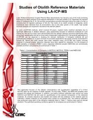
The following components are located on the front of the U-6000AT +<br />
Ultrasonic Nebulizer/Membrane Desolvator. Each lettered item<br />
corresponds with a callout in Figure 1–1.<br />
A<br />
B<br />
C<br />
D<br />
E<br />
F<br />
Transducer assembly. Piezoelectric transducer that converts RF<br />
energy to ultrasonic oscillations and nebulizes the liquid sample.<br />
Aerosol chamber stand. This component holds the aerosol<br />
chamber and transducer on the front of the glassware module.<br />
Aerosol chamber. Glassware that holds the transducer assembly,<br />
where the sample is introduced, nebulized and mixed with argon<br />
carrier gas before entering the U-tube.<br />
Sample/rinse adapter. Internal o-rings retain it on the spray<br />
chamber inlet tube, and a compression fitting holds the sample inlet<br />
tubing in place.<br />
U-tube. The nebulized sample is vaporized in the U-tube before<br />
entering the condenser.<br />
Heat cords. The heat cords are wrapped around the exterior of the<br />
U-tube. Temperature regulation is achieved by the “Heater”<br />
controller.<br />
1–3
U-6000AT + Ultrasonic Nebulizer/Membrane Desolvator Operator’s <strong>Manual</strong><br />
Introduction<br />
Figure 1–1. U-6000AT + Design--Front View.<br />
G<br />
H<br />
I<br />
J<br />
K<br />
Glassware module. Top module of ultrasonic nebulizer; houses<br />
transducer assembly, aerosol chamber, U-tube and condenser.<br />
Transducer RF cable. Cable that transmits the RF energy from<br />
the RF power supply to the transducer assembly.<br />
Sample inlet tubing. This tube delivers the liquid sample onto<br />
the transducer face for nebulization.<br />
Electronics module. Bottom module of ultrasonic nebulizer;<br />
houses drain pump, temperature controllers and RF power supply.<br />
Auxiliary rinse port. The luer fitting allows fast system rinse-out<br />
between samples.<br />
1–4
U-6000AT + Ultrasonic Nebulizer/Membrane Desolvator Operator’s <strong>Manual</strong><br />
Introduction<br />
L Operate switch. The push-on/push-off RF power control switch.<br />
It illuminates when the RF system is energized and operating.<br />
M Fast pump switch. The push-on/push-off high-speed drain pump<br />
control switch. It illuminates during rapid pumping of the spray<br />
chamber and drain tubing after rinse-out.<br />
N<br />
O<br />
P<br />
Heater controller (nebulizer). PID controller that regulates the<br />
temperature of the ultrasonic nebulizer’s heat cords.<br />
Cooler controller (nebulizer). PID controller that regulates the<br />
temperature of the ultrasonic nebulizer’s thermo-electric condenser.<br />
Heater controller (desolvator). PID controller that regulates the<br />
temperature of the membrane desolvator’s heaters.<br />
Q Flow meter. Digital readout of argon (sweep gas) flow, indicated<br />
units.<br />
R<br />
S<br />
Flow control. Pressure regulator adjustment to control argon<br />
(sweep gas) flow.<br />
Membrane Desolvator module. Pressure regulator adjustment to<br />
control argon (sweep gas) flow.<br />
1–5
U-6000AT + Ultrasonic Nebulizer/Membrane Desolvator Operator’s <strong>Manual</strong><br />
Introduction<br />
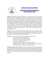
The following components are located on the back of the U-6000AT +<br />
Ultrasonic Nebulizer/Membrane Desolvator. Each lettered item<br />
corresponds with a callout in Figure 1–2.<br />
A<br />
B<br />
C<br />
D<br />
E<br />
F<br />
G<br />
Sample out tubing. Tubing that transfers the sample directly to<br />
the Membrane Desolvator or to the ICP.<br />
Top cover captive screws. Threaded fastener that securely locks<br />
the top cover to the chassis.<br />
Cooling fan. Removes the heat generated by the thermoelectric<br />
coolers.<br />
Top cover captive screws. Threaded fastener that securely locks<br />
the top cover to the chassis.<br />
Top cover. Removable, protects user from the heat cords and gives<br />
access to the sample out interface.<br />
Glassware module. Top module of ultrasonic nebulizer; houses<br />
transducer assembly, aerosol chamber, U-tube and condenser.<br />
Argon inlet fitting. Connection for the argon carrier gas.<br />
H Drain tubing. There are three places of drainage, aerosol<br />
chamber, primary condenser (heated tube), and the secondary<br />
condenser (thermoelectrics).<br />
I<br />
J<br />
Electronics module. Bottom module of ultrasonic nebulizer;<br />
houses drain pump, temperature controllers and RF power supply.<br />
Waste drain tubing. The three drains (from H above) after the<br />
peristaltic pump.<br />
K Drain pump. Three channel, four roller peristaltic pump used to<br />
pump the drains.<br />
L<br />
Drain pump tubing. Three pieces of peristaltic pump tubing.<br />
1–6
U-6000AT + Ultrasonic Nebulizer/Membrane Desolvator Operator’s <strong>Manual</strong><br />
Introduction<br />
Figure 1–2. U-6000AT + Design—Back View.<br />
M<br />
Membrane Desolvator module. The lower unit that contains the<br />
temperature controlled membrane and sweep gas control.<br />
N<br />
O<br />
P<br />
Q<br />
Aerosol-out (to ICP). The exit port from the membrane which<br />
connects directly to the ICP.<br />
Sweep gas inlet. Argon supply (40-120psi).<br />
Sweep gas outlet. The exit for the outer sweep gas which is taken<br />
to exhaust.<br />
Membrane rinse port. Used to rinse the membrane.<br />
1–7
U-6000AT + Ultrasonic Nebulizer/Membrane Desolvator Operator’s <strong>Manual</strong><br />
Introduction<br />
R Aerosol-in (from ultrasonic nebulizer). Sample from the<br />
ultrasonic nebulizer to the membrane.<br />
S<br />
T<br />
U<br />
V<br />
W<br />
X<br />
Y<br />
Z<br />
Cooling fan cover (desolvator). Removes the heat generated by<br />
the heated membrane .<br />
External connection (desolvator). Unused at this time.<br />
AC power module (desolvator). Mains voltage connected here.<br />
AC power switch (desolvator). Turns the desolvator power on or<br />
off.<br />
Fuse drawer (desolvator). Mains fuses for the desolvator.<br />
Voltage selector. Selects between 120 and 240VAC. This applies<br />
only to the membrane desolvator, not the ultrasonic nebulizer<br />
which is internally wired for a specific voltage.<br />
External connection (nebulizer). Used to check the oscillator<br />
bias voltage and also to interface to other <strong>CETAC</strong> peripherals.<br />
MOSFET transistor. Amplifier for the oscillator circuitry.<br />
AA AC power module (nebulizer). Mains voltage connected here.<br />
BB AC power switch (nebulizer). Turns the ultrasonic nebulizer<br />
power on or off.<br />
CC Fuse drawer (nebulizer).<br />
nebulizer.<br />
Mains fuses for the ultrasonic<br />
DDRF circuit breaker. This breaker protects the oscillator circuitry<br />
from faulty transducers or connections.<br />
The following standard components/accessories are also included with<br />
each U-6000AT + Ultrasonic Nebulizer/Membrane Desolvator:<br />
1–8
U-6000AT + Ultrasonic Nebulizer/Membrane Desolvator Operator’s <strong>Manual</strong><br />
Introduction<br />
• ICP interface kit. All parts to successfully interface to the ICP,<br />
including torch adapters and spray chambers, if needed.<br />
• Spare fuse kit. Contains replacement fuses for the U-6000AT + .<br />
• Spare drain pump tubing kit. Replacement tubing for the drain<br />
peristaltic pump.<br />
• Sample inlet extension tubing kit. This is used when the sample<br />
peristaltic pump cannot be placed close enough to the<br />
U-6000AT + to make a proper connection.<br />
• Argon tubing kit. Contains all the necessary tubing to interface<br />
argon with the U-6000AT + .<br />
Optional Accessories<br />
If you are connecting the U-6000AT + to a second ICP, want to automate<br />
sample introduction or between sample rinse-out, you may wish to<br />
purchase optional accessories for the Ultrasonic Nebulizer/Membrane<br />
Desolvator. The following accessories are available for the U-6000AT + :<br />
• Acid-proof O-ring kit.<br />
• Organics tubing kit.<br />
• Utility cart. Holds the U-6000AT + and related pieces.<br />
• ASX-510 Auto sampler.<br />
Note:<br />
Contact <strong>CETAC</strong> <strong>Technologies</strong> if you need additional accessories not<br />
listed, need added features to integrate the U-6000AT + Ultrasonic<br />
Nebulizer/Membrane Desolvator into your analytical system, or have<br />
unique requirements. Research and development of new features and<br />
1–9
U-6000AT + Ultrasonic Nebulizer/Membrane Desolvator Operator’s <strong>Manual</strong><br />
Introduction<br />
accessories for the U-6000AT + Ultrasonic Nebulizer/Membrane<br />
Desolvator, often inspired by customer requests, is a continuing activity<br />
of <strong>CETAC</strong> <strong>Technologies</strong>.<br />
1–10
2<br />
Preparing for<br />
Installation
Preparing for<br />
Installation<br />
Installing the U-6000AT + requires preparation. Before you install the<br />
system you should evaluate the physical arrangement of the laboratory<br />
to choose a suitable location. Once you choose a location, you must<br />
carefully unpack the U-6000AT + prior to beginning the installation.<br />
This chapter discusses what requirements must be met when you<br />
choose a location for the U-6000AT + . It also describes how to unpack<br />
the U-6000AT + before installation.<br />
Choosing a Location<br />
Choosing a location for the U6000AT + involves evaluating the lab<br />
environment for the availability of space and power. For the U-<br />
6000AT + to function optimally, the location you select must meet<br />
specific requirements associated with each of these items. The<br />
following sections discuss space and power requirements.<br />
Space Requirements<br />
Most analytical applications benefit from the shortest sample flow.<br />
path. Therefore, you should place the U-6000AT + close to the analytical<br />
instrument. The recommended minimum footprint for countertop<br />
installation of the U-0006AT + is 18” x 18” (45 cm x 45 cm).<br />
Power Requirements<br />
Place the U-0006AT + within 1.2 meters of a power outlet. The voltage<br />
input requirements are 100-120 VAC ± 10%, 50/60 Hz, 9A, or 220-240<br />
VAC ± 10%, 50/60 Hz, 4.5A, depending on the model.
U-6000AT + Ultrasonic Nebulizer/Membrane Desolvator Operator’s <strong>Manual</strong><br />
Preparing for Installation<br />
There is a fuse drawer at the rear of the electronic module for both the<br />
ultrasonic nebulizer and the membrane desolvator. Each fuse drawer<br />
contains two fuses. You can remove the fuse drawer by unlatching the<br />
fuse holder with a small screwdriver.<br />
WARNING<br />
Disconnect the input power before attempting any fuse servicing.<br />
For the ultrasonic nebulizer, replace the fuses with a GMC 5A, 250V<br />
slo-blow type for 100-120 VAC input voltage or a GMC 2.5A, 250V sloblo<br />
type for 220-240 VAC input voltage.<br />
For the membrane desolvator, replace the fuses with a GMC 5A, 250V<br />
slo-blow type for all input voltages.<br />
WARNING<br />
Replacement with a higher-rated fuse without first consulting<br />
<strong>CETAC</strong> <strong>Technologies</strong> or an authorized representative is done<br />
solely at the user’s risk and is not recommended. Blown fuses<br />
indicate an abnormal condition, and replacement should be<br />
uncommon. Call Customer Service and Support if repeated fuse<br />
blowing occurs.<br />
2–3
U-6000AT + Ultrasonic Nebulizer/Membrane Desolvator Operator’s <strong>Manual</strong><br />
Preparing for Installation<br />
Unpacking the U-6000AT +<br />
Inspect external packaging upon receipt for holes, tears, smashed<br />
corners, or any other outward signs of damage from rough handling or<br />
abuse during shipment. Inspect all items during unpacking and notify<br />
the carrier immediately of any concealed damage.<br />
Remove packing checklist from the shipping container, and check off<br />
items against it. Leave accessories in the packing unit until you are<br />
ready to install them on the U-6000AT + .<br />
Note:<br />
Do not throw away the factory packaging. Keep it for possible future<br />
use. This is one of the warranty conditions.<br />
CAUTION<br />
If condensation forms on or inside the U-6000AT + , allow it to dry<br />
thoroughly before connecting it to an AC power source and operating it.<br />
Failure to do so may cause equipment damage.<br />
ICP Requirements<br />
To achieve optimum performance from the U-6000AT + , the ICP system<br />
must be in good operating condition. Check the ICP performance using<br />
a conventional pneumatic nebulizer before the U-6000AT + installation.<br />
If the detection limits do not meet instrument specifications, consult<br />
the ICP manufacturer for assistance. If the detection limits are within<br />
the manufacturer’s specifications, begin installation of the U-6000AT +<br />
system.<br />
2–4
3<br />
Installing the U-6000AT +<br />
Ultrasonic Nebulizer /<br />
Membrane Desolvator
Installing the U-6000AT +<br />
System<br />
The U-6000AT + is designed for easy installation.<br />
To install the U-60000AT + , you must first complete the following tasks.<br />
Each of these tasks will be discussed in detail later in this chapter.<br />
• Drainage system assembly<br />
• Liquid sample delivery and rinse system<br />
• Establishing external connections<br />
• Connecting the U-6000AT + to the ICP torch<br />
WARNING<br />
Ensure that AC power is off (0 showing at the top edge of the<br />
rocker switches) on both the Ultrasonic Nebulizer and<br />
Membrane Desolvator before proceeding with installation.<br />
Drainage System Assembly<br />
The U-6000AT + drainage system removes both sample waste from the<br />
spray chamber and condensed solvent from the condenser. It consists<br />
of a built-in three channel four roller peristaltic pump and the<br />
associated pump tubing and connectors.<br />
Connect the three lengths of 1.8” I.D. Tygon tubing to the outlet of the<br />
fittings from the pump. Place the other ends of the tubing into the<br />
waste bottle. The drain pump tubing on the U-6000AT + is user<br />
replaceable (see Chapter 6 Maintaining the U-6000AT + Ultrasonic<br />
Nebulizer / Membrane Desolvator).
U-6000AT + Ultrasonic Nebulizer / Membrane Desolvator Operator’s <strong>Manual</strong><br />
Installing the U-6000AT + Ultrasonic Nebulizer / Membrane Desolvator<br />
Liquid Sample Delivery and Rinse System<br />
Sample Inlet Tubing<br />
The sample/rinse adapter holds the sample tubing in place. It is<br />
mounted and aligned during assembly and should require no<br />
adjustment prior to use.<br />
Sample liquid is delivered to the U-6000AT + transducer through 0.5<br />
mm I.D. PEEK sample tubing which is inserted through the glass<br />
sample inlet tube located at the base of the aerosol chamber.<br />
For high concentrations of sulfuric or nitric acid, it is recommended<br />
that the PEEK sample inlet tubing be replaced with the clear Tefzel<br />
sample inlet tubing supplied as an accessory with the U-6000AT + . The<br />
Tefzel tubing performs much better when using these types of acids. To<br />
install the Tefzel tubing, follow the procedure for the PEEK sample<br />
inlet tubing.<br />
For proper sample delivery, the end of the sample inlet tubing is cut at<br />
an angle of approximately 60 degrees. As previously mentioned, the<br />
sample/rinse adapter is mounted and aligned at the factory, however, it<br />
may be necessary to adjust this adapter or remove it and re-cut the end<br />
of the tubing periodically for optimum sample delivery. This procedure<br />
is outlined on the following pages:<br />
3–3
U-6000AT + Ultrasonic Nebulizer / Membrane Desolvator Operator’s <strong>Manual</strong><br />
Installing the U-6000AT + Ultrasonic Nebulizer / Membrane Desolvator<br />
Figure 3–1. Sample Inlet Adapter and Tubing.<br />
1 Remove the sample/rinse adapter (G) from the glass sample inlet<br />
tube by carefully sliding the adapter along the glass sample inlet<br />
tube.<br />
2 Re-cut the sample tubing (F) at a 60° angle, using a sharp razor<br />
blade: an improper cut or a blunt tip may cause inefficient<br />
nebulization.<br />
3 Loosen the compression fitting nut (J) which holds the PEEK<br />
sample inlet tubing. Adjust the tubing position to account for<br />
3–4
U-6000AT + Ultrasonic Nebulizer / Membrane Desolvator Operator’s <strong>Manual</strong><br />
Installing the U-6000AT + Ultrasonic Nebulizer / Membrane Desolvator<br />
the removed section. Tighten the sample inlet compression<br />
fitting nut to hold the tubing in place.<br />
4 Replace the adapter. First insert the sample inlet tubing, then<br />
slide the sample/rinse adapter back onto the glass tube.<br />
5 Slide the adapter until the sample tubing touches the face of the<br />
transducer. Lightly pull the adapter back to form a very narrow<br />
gap (approximately 0.2 - 0.4 mm) between the transducer and the<br />
tubing. This position allows proper adhesion of sample solution<br />
onto the transducer without any contact between the tubing and<br />
the transducer. At this point, the end of the sample tubing<br />
should be parallel to the transducer face.<br />
6 If the length of the sample inlet tubing is not correct, remove the<br />
sample inlet adapter. Repeat steps 3 through 5 until proper<br />
adjustment is achieved.<br />
The auxiliary rinse port on the sample/rinse inlet adapter (Figure 3-2)<br />
provides the capability for rapidly cleaning the transducer face plate<br />
between samples. This reduces memory effects. A rinse bottle is<br />
provided for this purpose. The auxiliary rinse port should always have<br />
the male luer plug inserted if the rinse port is not utilized. (The<br />
<strong>CETAC</strong> Auto Rinse System 2000 is available for automatic rinsing<br />
when an autosampler is used). To rinse between samples:<br />
1 Remove the male luer plug (I) from the auxiliary rinse port of the<br />
sample/rinse adapter; use a counter-clockwise twist.<br />
2 Attach the male luer fitting. It is attached to the rubber tubing<br />
on the rinse bottle connect to the rinse port using a clockwise<br />
motion.<br />
3 Fill the auxiliary rinse bottle with deionized water.<br />
4 Gently squeeze the rinse bottle handle 2-5 times. Deliver<br />
deionized water to the transducer face. Rinse water should<br />
splash around the transducer area of the aerosol chamber each<br />
time the handle is squeezed.<br />
3–5
U-6000AT + Ultrasonic Nebulizer / Membrane Desolvator Operator’s <strong>Manual</strong><br />
Installing the U-6000AT + Ultrasonic Nebulizer / Membrane Desolvator<br />
Figure 3–2. Sample Inlet Tubing Extension.<br />
Sample Inlet Tubing Extension<br />
Connecting the sample uptake peristaltic pump tubing directly to the<br />
U-60000AT + is the most desirable arrangement. However, this may not<br />
always be possible or desirable. A sample inlet tubing extension kit is<br />
provided to accommodate this situation. The components of the sample<br />
inlet tubing extension kit are shown in Figure 3-2.<br />
Establishing External Connections<br />
The next step in the installation process involves connecting the<br />
U-6000AT + to the power source, connecting the Ultrasonic Nebulizer to<br />
3–6
U-6000AT + Ultrasonic Nebulizer / Membrane Desolvator Operator’s <strong>Manual</strong><br />
Installing the U-6000AT + Ultrasonic Nebulizer / Membrane Desolvator<br />
the Membrane Desolvator, and connecting the Membrane Desolvator to<br />
the ICP Spectrometer. The following sections explain how to establish<br />
these connections.<br />
Connecting the U-6000AT + to the Power Source<br />
Voltage-specified power cords are supplied with each U-6000AT + .<br />
WARNING<br />
Use only these power cords or exact replacements.<br />
To connect the Ultrasonic Nebulizer to a power source, plug the cord in<br />
the power module located on the back panel of the nebulizer. Then<br />
plug the cord into an appropriate AC outlet (110 or 220 VAC ±10%<br />
50/60 Hz depending on the model). Establish the same power<br />
connection for the Membrane Desolvator.<br />
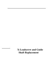
Connecting the Nebulizer Gas to the<br />
Ultrasonic Nebulizer<br />
Connect the nebulizer gas from the ICP instrument to the Ultrasonic<br />
Nebulizer using the ARGON IN connector (Figure 3-3) and 3/16” I.D.<br />
Tygon tubing.<br />
Note:<br />
Some ICPs utilize a pressure switch on the nebulizer gas that will not<br />
allow the user to reduce the pressure enough to get the 0.6L/min or less<br />
argon flow required by the U-6000AT + . With these ICPs, it is necessary<br />
to use an auxiliary flow restrictor between the nebulizer gas supply and<br />
the U-6000AT + ARGON IN connector for control of the nebulizer argon<br />
flow. This restrictor will be provided by <strong>CETAC</strong> when necessary.<br />
3–7
U-6000AT + Ultrasonic Nebulizer / Membrane Desolvator Operator’s <strong>Manual</strong><br />
Installing the U-6000AT + Ultrasonic Nebulizer / Membrane Desolvator<br />
Connecting the Ultrasonic Nebulizer to the<br />
Membrane Desolvator<br />
1 Ensure that AC power is disconnected from the Ultrasonic<br />
Nebulizer and the heated U-tube is cooled off before beginning.<br />
2 Remove the Ultrasonic Nebulizer top cover. Do this by releasing<br />
the rear captive panel screws and carefully sliding the cover<br />
forward and then lifting it off. Locate the glass sample outlet<br />
tube located at the condenser outlet.<br />
3 Connect the glass sample outlet tube of the Ultrasonic Nebulizer<br />
to the FROM NEBULIZER port on the back of the membrane<br />
desolvator using 3/16” I.D. Tygon tubing. Place the Tygon tubing<br />
in the SAMPLE OUT opening or it will become pinched when the<br />
top cover is reinstalled and will cause unacceptable nebulizer<br />
performance.<br />
4 Replace the top cover and tighten the rear captive panel screws.<br />
Note:<br />
If use of the membrane desolvator is not desired, simply attach the<br />
Tygon tubing from the SAMPLE OUT opening directly to the ICP.<br />
Depending on the ICP manufacturer or model, a spray chamber or torch<br />
adapter may be needed. These adapters are supplied by <strong>CETAC</strong>.<br />
Connect the nylon sweep gas line to the SWEEP GAS IN port on the<br />
back of the Membrane Desolvator. A 1/4” Swagelok fitting is used. The<br />
other end of the sweep gas line may be attached to a separate argon<br />
cylinder or to a tee coming off the main instrument argon supply.<br />
Connect 3/16” I.D. Tygon tubing to the SWEEP GAS OUT port on the<br />
back of the membrane desolvator. Attach the other end of the tubing to<br />
the ICP exhaust vent.<br />
3–8
U-6000AT + Ultrasonic Nebulizer / Membrane Desolvator Operator’s <strong>Manual</strong><br />
Installing the U-6000AT + Ultrasonic Nebulizer / Membrane Desolvator<br />
Figure 3–3. U-6000AT + Tubing Diagram--Aqueous Samples.<br />
Figure 3–4. U-6000AT + Tubing Diagram--Organic Samples.<br />
3–9
U-6000AT + Ultrasonic Nebulizer / Membrane Desolvator Operator’s <strong>Manual</strong><br />
Installing the U-6000AT + Ultrasonic Nebulizer / Membrane Desolvator<br />
Additional Connections for the Analysis of<br />
Organic Solvents<br />
WARNING<br />
• Prior to the analysis of volatile organic solvents, the user<br />
should provide an adequate container for safely collecting<br />
condensate from the sweep gas out line prior to exhaust<br />
(Figure 3-4). Precautions should be taken to assure solvents<br />
in condensate container are not mixed.<br />
• Under other conditions the user must always insure<br />
connection of the sweep gas to a safe fume exhaust.<br />
Connecting the Membrane Desolvator to the Analytical<br />
Instrument<br />
Depending on the ICP manufacturer and model, a torch adapter or<br />
spray chamber adapter is supplied for interfacing the U-6000AT + to the<br />
ICP.<br />
1 Mount the spray chamber/torch adapter on the ICP torch.<br />
2 Connect 3/16” I.D. tubing from the TO ICP port on the back of the<br />
membrane desolvator to the adapter (if necessary) on the ICP<br />
torch.<br />
3–10
4<br />
Verifying Installation
Verifying Installation<br />
Once installation of the U-6000AT + is complete, it is important to verify<br />
that you have installed the system correctly. Attempting to use the<br />
U-6000AT + before ensuring that it is installed correctly may result in<br />
damage to the system.<br />
Verifying installation of the U-6000AT + consists of three parts:<br />
• Initial operation procedure<br />
• ICP operation<br />
• System Optimization<br />
This chapter explains initial operation of U-6000AT + , ICP operation,<br />
and how to optimize the U-6000AT + .<br />
Initial Operating Procedure<br />
1 Plug the supplied power cords into the ultrasonic nebulizer and<br />
the membrane desolvator and then into the AC supply outlets.<br />
2 Turn on the power switch and allow the heater and condenser<br />
stages to preheat and precool. After approximately 10-15<br />
minutes, all stages should be operating at a steady state as<br />
indicated by HEATER and COOLER temperature readings of<br />
140°C ± 2° and 3°C ± 1°, on the ultrasonic nebulizer and 160°C ±<br />
2° on the HEATER for the membrane desolvator.
U-6000AT + Ultrasonic Nebulizer / Membrane Desolvator Operator’s <strong>Manual</strong><br />
Verifying Installation<br />
Note:<br />
All temperature controllers are factory programmed and preset.<br />
Temperature settings should not be changed unless absolutely<br />
necessary to obtain acceptable nebulizer performance. Do not exceed<br />
controller settings of 120-160°C (HEATER’s) and -5-10°C (COOLER).<br />
3 Ensure the drain pump pressure shoe is engaged and all lines<br />
are connected.<br />
4 With the heating and cooling temperatures stabilized, turn on<br />
the nebulizer gas from the ICP and adjust flow to 0.6 L/min.<br />
5 Connect the sample peristaltic pump to the 0.5mm I.D. PEEK<br />
sample tubing. If the PEEK sample tubing is not long enough to<br />
connect to the sample peristaltic pump, a three foot piece of 0.5<br />
mm I.D. Tefzel extension tubing and necessary fittings have been<br />
included with the unit.<br />
6 Turn on the sample delivery pump and deliver deionized water<br />
at 2.5 ml/min.<br />
7 Press the OPERATE switch. The yellow switch light will<br />
illuminate and a dense mist should be observed inside the<br />
aerosol chamber.<br />
4–3
U-6000AT + Ultrasonic Nebulizer / Membrane Desolvator Operator’s <strong>Manual</strong><br />
Verifying Installation<br />
Note:<br />
OPERATE switch illumination indicates the delivery of RF Power to the<br />
transducer. If the OPERATE switch does not illuminate after the<br />
OPERATE switch is pressed or the lamp goes out during operation, this<br />
indicates a fault in the RF system. Immediately shut down the unit and<br />
see Chapter 7, “Troubleshooting the U-6000AT + Ultrasonic<br />
Nebulizer/Membrane Desolvator”.<br />
8 Prepare 250 ml of a 0.5% (v/v) solution of hydrofluoric acid and<br />
nebulize it for 20 to 30 seconds. The mist in the aerosol chamber<br />
should be dense and steady at this point. If not, see Chapter 7,<br />
“Troubleshooting the U-6000AT + Ultrasonic Nebulizer/Membrane<br />
Desolvator”.<br />
Note:<br />
Although dilute hydrofluoric acid solutions will not harm the glassware of<br />
the U-6000AT + or the ICP when nebulized for short periods, it should<br />
only be used when the transducer face becomes dirty, which is<br />
evidenced by weak or intermittent mist generation.<br />
Reserve the remaining solution for future use.<br />
9 Change the sample to deionized water and observe aerosol<br />
chamber drainage after 10-15 minutes of operation. If drainage<br />
is sufficient, there will be no fluid buildup in the aerosol<br />
chamber drain. Should a buildup occur, press the FAST PUMP<br />
switch until the fluid is cleared and check the drain tubing for<br />
leaks, restrictions, or insufficient pump shoe pressure. Repeat<br />
the drainage test. If drainage is still insufficient, shut down the<br />
U-6000AT + and see chapter 7 - Troubleshooting.<br />
10 Turn off the OPERATE switch, the sample peristaltic pump, and<br />
the nebulizer gas supply to the ICP.<br />
4–4
U-6000AT + Ultrasonic Nebulizer / Membrane Desolvator Operator’s <strong>Manual</strong><br />
Verifying Installation<br />
ICP Operation<br />
1 Ignite the ICP plasma as instructed in the ICP operating<br />
manual. The nebulizer gas flow rate should be set at a 0.6<br />
L/min; the sweep gas at 2.0 L/min.<br />
2 Press the OPERATE switch to energize the transducer of the<br />
ultrasonic nebulizer.<br />
3 Prepare and aspirate a 100 mg/ml solution of yttrium into the<br />
plasma. The emission color and intensity in the plasma should<br />
be similar to that found when 1000 mg/ml of yttrium is aspirated<br />
with a pneumatic nebulizer. If the yttrium emission is weak,<br />
check for gas leaks in the U-6000AT + or ICP system.<br />
System Optimization<br />
It may be necessary to optimize the ICP system after installation of the<br />
U-6000AT + . Optimization procedures may include adjustment of gas<br />
flows, sample uptake rate, plasma viewing or sampling positions, ion<br />
optical settings, etc. Usually the signal-to-noise or signal to background<br />
ratio is the primary criterion for optimization. For detailed instructions<br />
on system optimization for aqueous or organic samples, perform the<br />
ICP/U-6000AT + Optimization Procedures. After the system has been<br />
optimized, the U-6000AT + is ready for routine operation.<br />
4–5
U-6000AT + Ultrasonic Nebulizer / Membrane Desolvator Operator’s <strong>Manual</strong><br />
Verifying Installation<br />
Note:<br />
Extreme conditions which may cause unstable plasma formation, torch<br />
erosion, or high reflected power should be avoided.<br />
ICP-AES/Ultrasonic Nebulizer Optimization Procedure<br />
1 Recommended operating conditions and operating ranges for<br />
aqueous sample analysis without the membrane desolvator for<br />
ICP-AES:<br />
Normal<br />
Condition Range<br />
ICP forward power 1200 W 800-1500 W<br />
Outer gas flow rate (plasma) 15 L/min 12-20 L/min<br />
Intermediate gas flow rate 0.5 L/min 0.0-2.0 L/min<br />
(auxiliary)<br />
Injector gas flow rate 0.7 L/min 0.3-1.5 L/min<br />
(nebulizer)<br />
Observation height 15 mm 10-20 mm<br />
Sample uptake rate 2.5 mL/min 1.0-3.0 mL/min<br />
Ultrasonic nebulizer<br />
(heating temperature) 140 °C 120-160°C<br />
(cooling temperature) 3°C -5-10° C<br />
2 Optimization of the ICP and the ultrasonic nebulizer may be<br />
necessary to achieve the optimum sensitivity for specific elements<br />
in various aqueous samples. S/B ratios or S/N ratios may be used<br />
as the objective for optimization procedures.<br />
3 For the initial start-up procedure, the recommended operating<br />
conditions listed above may be used. These parameters represent<br />
compromise operating conditions for most elements and most<br />
aqueous samples and may be used satisfactory for many<br />
applications. Optimum conditions may necessary, depending<br />
upon the ICP system used.<br />
4–6
U-6000AT + Ultrasonic Nebulizer / Membrane Desolvator Operator’s <strong>Manual</strong><br />
Verifying Installation<br />
4 The recommended operating ranges for the ICP and the<br />
ultrasonic nebulizer are also listed above. Optimization of other<br />
parameters is usually not required; they are usually preset to the<br />
nominal values listed above.<br />
ICP-AES/U-6000AT + Optimization Procedure:<br />
1 Recommended operating conditions and ranges for organic<br />
sample analysis with the membrane desolvation connected to the<br />
ultrasonic nebulizer. ICP-AES detection is used.<br />
Normal<br />
Condition Range<br />
ICP forward power 1400 W 800-1500 W<br />
Outer gas flow rate (plasma) 15 L/min 12-20 L/min<br />
Intermediate gas flow rate 0.5 L/min 0.0-2.0 L/min<br />
(auxiliary)<br />
Injector gas flow rate 0.7 L/min 0.3-1.5 L/min<br />
(nebulizer)<br />
Observation height 15 mm 10-20 mm<br />
Sample uptake rate 2.5 mL/min 1.0-3.0 mL/min<br />
Ultrasonic nebulizer<br />
(heating temperature) 140°C 120-160°C<br />
(cooling temperature) 3°C -5-10° C<br />
Membrane Desolvator<br />
(heating temperature) 160°C 120-160°C<br />
Sweep gas flow 2.0 L/min 1.4-2.4 L/min<br />
2 Prepare a 1ppm solution of an appropriate tuning element (e.g.<br />
Mn) in 2-propanol (isopropyl alcohol).<br />
3 Start the ICP-AES and introduce the tuning solution via the<br />
U-6000AT + .<br />
4 Adjust parameters such as nebulizer gas flow, sweep gas flow,<br />
observation height, plasma forward power, etc.. to obtain the<br />
best signal-to-background ratio.<br />
4–7
U-6000AT + Ultrasonic Nebulizer / Membrane Desolvator Operator’s <strong>Manual</strong><br />
Verifying Installation<br />
ICP-MS/U-6000AT + Optimization Procedure<br />
1 Recommended operating conditions and ranges for aqueous<br />
sample analysis with the membrane desolvator connected to the<br />
ultrasonic nebulizer. ICP-MS detection is used.<br />
Normal<br />
Condition Range<br />
ICP forward power 1200 W 800-1500 W<br />
Outer gas flow rate (plasma) 15L/min 12-20 L/min<br />
Intermediate gas flow rate 0.5L/min 0.0-2.0 L/min<br />
(auxiliary)<br />
Injector gas flow rate 0.6 L/min 0.3-1.5 L/min<br />
(nebulizer)<br />
Sample uptake rate 2.5 mL/min 0.1-3.0 mL/min<br />
Ultrasonic nebulizer<br />
(heating temp) 140°C 120-160°C<br />
(cooling temp) 3°C -5-10°C<br />
Membrane desolvator heating temp 160°C 120-160°C<br />
Sweep gas flow 2.0 L/min 1.4-2.4 L/min<br />
2 Prepare a 10 ppb solution of Li, Co, In, Ce, and Pb in 1% HNO3.<br />
3 Start the ICP-MS and move to a graphics mode.<br />
4 Introduce the above solution to the ICP-MS using the U-6000AT + .<br />
Monitor at least Ce(140), CeO(156), and In(115).<br />
5 Adjust parameters such as nebulizer gas flow, sweep gas flow,<br />
sampling position, etc., to obtain high Ce and In signal and low<br />
CeO signal. The CeO/Ce ratio should be 0.04% or lower.<br />
ICP-MS/U-6000AT + Optimization Procedure<br />
1 Recommended operating conditions and ranges for organic<br />
sample analysis with the membrane desolvator connected to the<br />
ultrasonic nebulizer. ICP-MS detection is used.<br />
4–8
U-6000AT + Ultrasonic Nebulizer / Membrane Desolvator Operator’s <strong>Manual</strong><br />
Verifying Installation<br />
Normal<br />
Condition Range<br />
ICP forward power 1300 W 800-1500 W<br />
Outer gas flow rate (plasma) 15 L/min 12-20 L/min<br />
Intermediate gas flow rate 0.5 L/min 0.0-2.0 L/min<br />
(auxiliary)<br />
Injector gas flow rate 0.6L/min 0.3-1.5 L/min<br />
(nebulizer)<br />
Sample uptake rate 2.5 mL/min 1.0-3.0 mL/min<br />
Ultrasonic nebulizer heating temp 140°C 120-160°C<br />
Ultrasonic nebulizer cooling temp -5°C -5-10°C<br />
Membrane desolvator heating temp 160°C 120-160°C<br />
Sweep gas flow 2.0 L/min 1.4-2.4 L/min<br />
Oxygen flow (See note) 5 mL/min 0-10 mL/min<br />
2 Prepare a 10ppb solution of Li, Co, In, and Pb in 2-propanol<br />
(isopropyl alcohol).<br />
3 Start the ICP-MS and introduce the above solution via the<br />
U-6000AT+.<br />
4 Adjust parameters such as nebulizer gas flow, sweep gas flow,<br />
sampling position, ion optic voltages, etc., to obtain the best<br />
signal-to-noise ratio.<br />
Note:<br />
Oxygenated organic solvents (e.g., 2-propanol) may be run directly<br />
through the U-6000AT + to the ICP-MS. To analyze non-oxygenated<br />
organic solvents (e.g., toluene, hexane), a low flow of oxygen is teed<br />
into the sample line leading from the membrane desolvator to the ICP<br />
torch. This small amount of oxygen helps prevent carbon buildup on<br />
the ICP-MS sampling cones.<br />
4–9
U-6000AT + Ultrasonic Nebulizer / Membrane Desolvator Operator’s <strong>Manual</strong><br />
Verifying Installation<br />
4–10
5<br />
Using the U-6000AT +<br />
Ultrasonic Nebulizer /<br />
Membrane Desolvator
Using the U-6000AT + Ultrasonic<br />
Nebulizer / Membrane Desolvator<br />
The U-6000AT + is both reliable and easy to use. Before using the<br />
U-6000AT + , however, ensure that your lab environment provides<br />
operating conditions that will prolong the life of the U-6000AT + . Once<br />
the proper operating conditions are met, you can setup the system.<br />
Establishing Optimal Conditions<br />
The U-6000AT + operates reliably even under less than ideal conditions.<br />
It is not, however, indestructible. Malfunction or damage can occur if<br />
specific operating conditions are not met. Meeting these conditions<br />
requires that you create the proper lab environment, replace<br />
components that wear out under normal use, and purchase the<br />
appropriate supplies for use with the system. The following sections<br />
explain how to meet these conditions.<br />
Note:<br />
Damage or malfunction that results from unsatisfactory operating<br />
conditions may constitute misuse and abuse and be excluded from<br />
warranty coverage.<br />
Creating the Lab Environment<br />
To Create satisfactory operating conditions in your lab environment,<br />
follow these guidelines:<br />
• Operate the U-6000AT + in a conventional lab environment where<br />
the temperature is 50-86°F(10-30°C); the humidity is 20-70% non-
U-6000AT + Ultrasonic Nebulizer/Membrane Desolvator Operator’s <strong>Manual</strong><br />
Using the U-6000AT + Ultrasonic Nebulizer / Membrane Desolvator<br />
condensing; and the unit is not exposed to excessive flammable<br />
or corrosive materials.<br />
• Avoid rough handling of the U-6000AT + .<br />
expose the system to vibration or shock.<br />
If possible, do not<br />
• Protect the U-6000AT + from long-term exposure to condensation,<br />
corrosive materials, solvent vapor, continual standing liquids, or<br />
large spills. Exposures of this type can damage the electronics.<br />
• Observe the same general electrostatic discharge precautions as<br />
with any other integrated circuit electronic device. Low<br />
humidity environments, especially when combined with staticgenerating<br />
materials require maximum care.<br />
WARNING<br />
Discharge static buildup and ground to the U-6000AT + cabinet<br />
before performing any maintenance. Do not touch or shortcircuit<br />
bare contacts.<br />
Avoid using the U-6000AT + if strong electromagnetic interference or<br />
radio frequency interference is present.<br />
Replacing the U-6000AT + Components<br />
The following U-6000AT + components wear out under normal use and<br />
must be replaced periodically.<br />
• Transducer<br />
• Peristaltic pump tubing<br />
• Sample inlet tubing<br />
• Sample inlet extension tubing<br />
• Connecting Tygon tubing<br />
5–3
U-6000AT + Ultrasonic Nebulizer/Membrane Desolvator Operator’s <strong>Manual</strong><br />
Using the U-6000AT + Ultrasonic Nebulizer / Membrane Desolvator<br />
If you fail to replace these components when they deteriorate, the<br />
U-6000AT + will not function properly. For more information about<br />
replacing the U-6000AT + components, see Chapter 6 “Maintaining the<br />
U-6000AT + Ultrasonic Nebulizer / Membrane Desolvator.”<br />
Startup Procedure<br />
1 If the U-6000AT + has been turned off for an extended period of<br />
time, turn on the AC power switch and allow HEATER and<br />
COOLER temperatures to reach operating values and stabilize<br />
(approximately 10-15 minutes).<br />
2 Ignite the ICP plasma according to the ICP operating manual.<br />
Adjust operating parameters to optimized values.<br />
3 Press the Ultrasonic Nebulizer OPERATE switch.<br />
4 Turn on the sample peristaltic pump and deliver deionized<br />
water to the transducer. The ultrasonic nebulizer should<br />
stabilize in 15 minutes or less. If necessary, aspirate the dilute<br />
hydrofluoric solution to achieve a dense aerosol. The Ultrasonic<br />
Nebulizer is now ready for routine analysis.<br />
Shutdown Procedure<br />
1 Aspirate deionized water for at least 3 minutes. Momentarily<br />
rinse the entire transducer face plate and its surrounding area<br />
by introducing water through the auxiliary rinse port of the<br />
aerosol chamber.<br />
5–4
U-6000AT + Ultrasonic Nebulizer/Membrane Desolvator Operator’s <strong>Manual</strong><br />
Using the U-6000AT + Ultrasonic Nebulizer / Membrane Desolvator<br />
Note:<br />
Rinse-out is a recommended preventive maintenance procedure that<br />
will retard the accumulation of deposits on the transducer face plate and<br />
inside the glassware from corrosive samples.<br />
2 Turn off the sample peristaltic pump and let the nebulizer run<br />
dry for about 15 seconds.<br />
3 Turn off the OPERATE switch.<br />
4 Press the FAST PUMP switch and allow the pump to drain all<br />
liquid from the system. All liquid is considered drained when<br />
none can be observed flowing in the drain tubing.<br />
5 Turn off the FAST PUMP switch, followed by the AC power<br />
switch. Turn off the ICP plasma and the gas supplies according<br />
to the ICP system operating manual.<br />
Temperature Controller Operation<br />
The temperature controllers normal operation displays the actual<br />
temperature. The setpoint for each temperature controller can be<br />
viewed by simply pressing the button labeled SET on the respective<br />
temperature controller. When the button is released, the actual<br />
temperature is again displayed. The setpoint temperature can be<br />
changed by following the steps below:<br />
1 Press and hold the SET button and press the up or down arrow<br />
until the desired setpoint is reached<br />
2 Release the SET button and the actual temperature will be<br />
displayed.<br />
5–5
U-6000AT + Ultrasonic Nebulizer/Membrane Desolvator Operator’s <strong>Manual</strong><br />
Using the U-6000AT + Ultrasonic Nebulizer / Membrane Desolvator<br />
Switching from Organic Samples to Aqueous<br />
Samples and Vice Versa<br />
If organic solvents are to be analyzed after an aqueous sample with the<br />
U-6000AT + , 2-propanol (isopropyl alcohol) should be first nebulized for<br />
at least 5 minutes to clean out the system. Turn on the nebulizer gas<br />
flow to 0.7 L/min.<br />
When returning to aqueous samples, use 2-propanol again to clean the<br />
U-6000AT + , followed by deionized water. Again have the nebulizer gas<br />
on.<br />
WARNING<br />
The U-6000AT + is not recommended for the analysis of sulfuric<br />
acid.<br />
5–6
6<br />
Maintaining the U-6000AT +<br />
Ultrasonic Nebulizer /<br />
Membrane Desolvator
Maintaining the U-6000AT +<br />
Ultrasonic Nebulizer / Membrane<br />
Desolvator<br />
Routine maintenance of the U-6000AT + consists of daily and weekly<br />
cleaning of specific components. Routine maintenance also includes<br />
checking the U-6000AT + components for leaks or other damage.<br />
Additional periodic maintenance task may be required, including<br />
replacement of the following U-6000AT + components: Ultrasonic<br />
Nebulizer, transducer, peristaltic tubing, sample inlet tubing, sample<br />
inlet extension tubing, and Tygon tubing components.<br />
WARNING<br />
The U-6000AT + must be turned off and the AC power cords<br />
unplugged before performing any maintenance on the system.<br />
Transducer Assembly Removal<br />
1 Turn off the ultrasonic nebulizer and the ICP as described in the<br />
shutdown procedure.<br />
2 Disconnect the RF cable connector from the transducer<br />
assembly.
U-6000AT + Ultrasonic Nebulizer/Membrane Desolvator Operator’s <strong>Manual</strong><br />
Maintaining the U-6000AT + Ultrasonic Nebulizer / Membrane Desolvator<br />
Note:<br />
Note the orientation of the assembly and the transducer mounting<br />
screws before removal so the new transducer is reinstalled with the<br />
same orientation!<br />
3 Remove the transducer using a hex-head transducer wrench<br />
supplied with the U-6000AT + . Hold the transducer assembly<br />
firmly with one hand and remove the three spring-loaded socket<br />
head screws using the wrench.<br />
4 Carefully slide the transducer assembly and the O-ring straight<br />
out of the aerosol chamber neck. Wipe off any liquids or other<br />
contaminants inside the neck of the aerosol chamber. Take<br />
extreme care to avoid damaging the glass sample introduction<br />
tube - fragile!<br />
Transducer Assembly Installation<br />
1 The spare transducer assembly and screw/spring set is packaged<br />
in a protective box and collar which should not be discarded.<br />
Remove the spare transducer from the box and examine the<br />
crystal face for cleanliness. Cleaning can be accomplished by<br />
gently wiping the crystal face with a water moistened lint-free<br />
tissue.<br />
2 Place the O-ring back on the aerosol chamber and ensure the O-<br />
ring is smoothly seated against the glass bezel inside.<br />
3 Align the spare transducer assembly with one hand and replace<br />
the spring-loaded socket head screws. When tightened properly,<br />
the screw heads should be flush with the second fin (from the<br />
cable connector end) of the transducer heat sink. Proper seating<br />
of the O-ring con be observed through the aerosol chamber.<br />
6–3
U-6000AT + Ultrasonic Nebulizer/Membrane Desolvator Operator’s <strong>Manual</strong><br />
Maintaining the U-6000AT + Ultrasonic Nebulizer / Membrane Desolvator<br />
CAUTION<br />
Do not over tighten the screws!<br />
4 Reconnect the RF cable to the connector on the transducer<br />
assembly and store the transducer wrench.<br />
RF Circuit Breaker<br />
To protect the RF generator electronics, a re-setttable circuit breaker<br />
will trip (open) in approximately twenty seconds if a fault occurs<br />
anywhere in the RF output circuit or cable when the OPERATE switch<br />
is on. The RF circuit breaker is re-settable and is located on the right<br />
rear of the electronics module (next to the AC power module containing<br />
the power cord receptacle, AC power switch and fuse drawer). To reset<br />
a tripped RF circuit breaker:<br />
1 Turn the AC power switch off (0).<br />
2 Check the RF cable and connections at the transducer, bulkhead<br />
feed through on the glassware module and electronics module.<br />
3 Reset the RF circuit breaker by pressing the rocker switch down<br />
until it latches.<br />
4 Turn AC power and OPERATE switched on. If the RF circuit<br />
breaker trips again, contact you authorized service<br />
representative or <strong>CETAC</strong> <strong>Technologies</strong> for assistance.<br />
Main Fuse Replacement<br />
The main fuses are located in the AC power module fuse drawers<br />
located at the right rear of the electronics modules of the Ultrasonic<br />
Nebulizer and Membrane Desolvator. To replace blown fuses:<br />
6–4
U-6000AT + Ultrasonic Nebulizer/Membrane Desolvator Operator’s <strong>Manual</strong><br />
Maintaining the U-6000AT + Ultrasonic Nebulizer / Membrane Desolvator<br />
1 Turn the AC power switch to off (0) and disconnect the AC power<br />
cord.<br />
2 Use a small flat blade screwdriver to unlatch the fuse holder.<br />
3 Replace the defective fuse with a GMC 5A, 250V slo-blow if<br />
operating on 100/115 VAC or 230 VAC.<br />
WARNING<br />
Use of a different fuse other than those specified can damage the<br />
electrical components of the U-6000AT + , constitute a fire hazard<br />
or result in personal injury.<br />
4 Replace the power cord, turn AC power and OPERATE switches<br />
on. If the new fuses blow, do not attempt to operate the unit.<br />
Contact your authorized service representative or <strong>CETAC</strong><br />
<strong>Technologies</strong> for assistant.<br />
Drain Pump Tubing Replacement<br />
To replace pump tubing:<br />
1 Unlatch the pressure show.<br />
2 Remove the old pump tubing by snapping the tubing connectors<br />
out of the tubing keeper.<br />
3 Reuse the plastic connectors. Phar-Med tubing (3/32” I.D., 1/32”<br />
wall) is used on the peristaltic drain pump; it may be purchased<br />
pre-cut from <strong>CETAC</strong> <strong>Technologies</strong>. If using bulk tubing, cut<br />
three 3 3/4” lengths using a sharp razor blade.<br />
4 Place the new tubing with connectors in the tubing keeper.<br />
Firmly press the connectors into the tubing keeper slots until<br />
they lock in place.<br />
5 Reconnect all external drain tubing.<br />
6–5
U-6000AT + Ultrasonic Nebulizer/Membrane Desolvator Operator’s <strong>Manual</strong><br />
Maintaining the U-6000AT + Ultrasonic Nebulizer / Membrane Desolvator<br />
Rinse Procedure for the Membrane Desolvator<br />
The membrane may need to be thoroughly rinsed after the analysis of<br />
organic samples containing high concentrations of nonvolatile residues<br />
or after analysis of aqueous samples containing high concentrations of<br />
solids. The length of time between rinses in a routing operation<br />
depends on the types of samples analyzed. Analysis of samples<br />
containing less than 5% of nonvolatile residues is recommended. When<br />
the organic solvent removal efficiency decreases or the ICP becomes<br />
unstable, the membrane should be rinsed. The following procedure<br />
describes how to rinse the membrane desolvator. Please refer to Figure<br />
6-1 for the respective tubing diagram.<br />
Note:<br />
If aqueous samples were analyzed, 1% HNO3 may be used to rinse the<br />
membrane.<br />
1 Turn the AC power switch to off (0) and disconnect the AC power<br />
cords. Allow the heater to cool to room temperature.<br />
2 Disconnect the 3/16” Tygon tubing leading from the Ultrasonic<br />
Nebulizer to the Membrane Desolvator.<br />
3 Disconnect the 3/16” Tygon tubing leading from the membrane<br />
Desolvator to the ICP torch.<br />
4 Connect one of the rinse inlet Y-connectors between the From<br />
Nebulizer port and the Sweep Gas Out port.<br />
5 Connect the other rinse inlet Y-connector between the Rinse and<br />
To ICP ports.<br />
6 Fill the 50 mL glass syringe with toluene and fill the membrane<br />
via the syringe adapter through the From Nebulizer and Sweep<br />
Gas Out ports.<br />
6–6
U-6000AT + Ultrasonic Nebulizer/Membrane Desolvator Operator’s <strong>Manual</strong><br />
Maintaining the U-6000AT + Ultrasonic Nebulizer / Membrane Desolvator<br />
7 Let the solvent soak the membrane for about 10 minutes.<br />
8 Use another 50 mL of toluene to flush the membrane, collecting<br />
the overflow from the other Y-connector.<br />
9 Flush the membrane with air several times using an empty<br />
syringe.<br />
10 Reestablish power to the Membrane Desolvator and turn the AC<br />
power switch on. Adjust the sweep gas to 2.0 L/min and flush the<br />
membrane with Ar for at least 15 minutes.<br />
11 Reconnect the membrane desolvator to the Ultrasonic Nebulizer<br />
and the ICP torch.<br />
Figure 6–1. Tubing Connections for Rinsing the Membrane.<br />
6–7
7<br />
Troubleshooting the<br />
U-6000AT + Ultrasonic<br />
Nebulizer / Membrane<br />
Desolvator
Troubleshooting the U-6000AT +<br />
Ultrasonic Nebulizer / Membrane<br />
Desolvator<br />
The U-6000AT + is both easy to operate and reliable. However, problems<br />
with the system may occur. When the U-6000AT + does not function<br />
properly, try to isolate the problem to determine if it originates in the<br />
analytical instrument, sample preparation, the Ultrasonic Nebulizer, or<br />
the Membrane Desolvator.<br />
This chapter explains how to troubleshoot U-6000AT + problems. If you<br />
cannot solve a problem using the steps given in this chapter, contact<br />
<strong>CETAC</strong> <strong>Technologies</strong> Customer Service and Support.<br />
Phone: (800) 369-2822<br />
(402) 733-2829<br />
Fax: (402) 733-1932<br />
Heater and Cooler Temperature Controller<br />
Problems<br />
1 Heater controllers do not illuminate.<br />
Power cord not plugged into AC wall outlet. Plug in power cord.<br />
Main fuses blown. Replace main fuses (5A 250V Slo-Blo).
U-6000AT + Ultrasonic Nebulizer/Membrane Desolvator Operator’s <strong>Manual</strong><br />
Troubleshooting the U-6000AT + Ultrasonic Nebulizer / Membrane Desolvator<br />
2 Display of temperature controller reads “Er 4”.<br />
Open thermocouple, bad connection, or broken wire. Replace/repair<br />
thermo couple wire.<br />
3 Cooler temperature controller will not cool to setpoint.<br />
Thermoelectric cooler defective. Condenser module defective.<br />
Fan on back not running.<br />
4 Heater and Cooler temperature controller reads room<br />
temperature.<br />
Heat cord or condenser heating element fuse blown. Replace respective<br />
fuse.<br />
5 Heater temperature controller stops illuminating.<br />
Thermal safety switch tripped due to excessive temperature. Heat<br />
controller is defective or solid-state relay is defective.<br />
Mist/Aerosol Chamber Problems<br />
1 Poor and/or unstable mist generation.<br />
Sample inlet tubing improperly adjusted/cut. Readjust sample inlet<br />
tubing, or re-cut and readjust<br />
Sample uptake too low, nebulizer gas too high, transducer face dirty.<br />
Clean transducer face with 0.5%(v/v) hydrofluoric rinse solution.<br />
7–3
U-6000AT + Ultrasonic Nebulizer/Membrane Desolvator Operator’s <strong>Manual</strong><br />
Troubleshooting the U-6000AT + Ultrasonic Nebulizer / Membrane Desolvator<br />
Transducer failure. Replace transducer.<br />
Operate lamp does not illuminate, no aerosol present, RF circuit<br />
breaker open. Reset RF circuit breaker.<br />
If problem persists after resetting the RF circuit breaker. Replace the<br />
transducer.<br />
2 Water backing up into aerosol chamber.<br />
Drain system not functioning properly. Tighten pressure shoe or<br />
replace drain pump tubing.<br />
Sample inlet flow is too great.<br />
Plasma Problems<br />
1 Plasma flickers excessively or is unstable.<br />
Condenser drain system not functioning properly. Thaw condenser if<br />
frozen. Find blockage in drainage system.<br />
Check all gas line connections. Make sure all connections are tight and<br />
correct.<br />
7–4
Index
Index<br />
A<br />
accessories<br />
optional 1–9<br />
additional connections for the analysis of<br />
organic solvents 3–10<br />
analysis of organic solvents<br />
additional connections for 3–9<br />
analytical instrument<br />
connecting the membrane desolvator to<br />
3–10<br />
assembly<br />
drainage system 3–2<br />
controller<br />
temperature operation 5–4<br />
conventions used in this book xiii<br />
creating the lab environment 5–2<br />
D<br />
delivery<br />
liquid sample and rinse system 3–2<br />
drain pump tubing replacement 6–5<br />
drainage system assembly 3–2<br />
B<br />
book<br />
conventions used in this xiii<br />
how to use this xii<br />
who should read this xii<br />
C<br />
cautions xiv<br />
chamber problems<br />
mist/aerosol 7–3<br />
choosing a location 2–2<br />
circuit breaker<br />
RF 6–3<br />
components<br />
replacing the U-6000AT + 5–3<br />
ultrasonic nebulizer/membrane<br />
desolvator 1–2<br />
conditions<br />
establishing optimal 5–2<br />
connecting the membrane desolvator to the<br />
analytical instrument 3–10<br />
connecting the nebulizer gas to the<br />
ultrasonic nebulizer 3–7<br />
connecting the U-6000 + to the power<br />
source 3–7<br />
connecting the ultrasonic nebulizer to the<br />
membrane desolvator 3–8<br />
connections<br />
establishing external 3–7<br />
E<br />
environment<br />
creating lab 5–2<br />
establishing external connections 3–6<br />
establishing optimal conditions 5–2<br />
extension<br />
sample inlet tubing 3–7<br />
external<br />
establishing connections 3–7<br />
F<br />
fuse replacement<br />
main 6–3<br />
H<br />
heater and cooler temperature controller<br />
problems 7–2<br />
how to use this book xii<br />
I<br />
ICP operation 4–4<br />
ICP requirements 2–4<br />
ICP-AES ultrasonic nebulizer optimization<br />
procedure 4–5<br />
ICP-AES/U-6000AT + optimization<br />
procedure 4–7
U-6000AT + Ultrasonic Nebulizer/Membrane Desolvator Operator’s <strong>Manual</strong><br />
Index<br />
ICP-MS/U-6000AT + optimization<br />
procedure 4–8, 4–9<br />
information<br />
where to go for more xiv<br />
initial operating procedure 4–2<br />
inlet<br />
sample tubing 3–2<br />
sample tubing extension 3–7<br />
installation<br />
preparing for 2–2<br />
transducer assembly 6–2<br />
verifying 4–2<br />
installing the U-6000AT + 3–2<br />
instructions xiii<br />
introduction 1–2<br />
L<br />
lab environment<br />
creating the 5–2<br />
liquid sample delivery<br />
and rinse system 3–3<br />
location<br />
choosing a 2–2<br />
M<br />
main fuse replacement 6–4<br />
maintaining the U-6000AT + 6–2<br />
membrane desolvator<br />
connecting to the analytical instrument<br />
3–10<br />
connecting to the ultrasonic nebulizer<br />
3–8<br />
rinse procedure for 6–4<br />
membrane desolvator/ultrasonic nebulizer<br />
components 1–2<br />
mist/aerosol chamber problems 7–3<br />
N<br />
nebulizer gas<br />
connecting to the ultrasonic nebulizer<br />
3–7<br />
O<br />
operating procedure<br />
initial 4–2<br />
operation<br />
ICP 4–3<br />
temperature controller 5–4<br />
optimal conditions<br />
establishing 5–2<br />
optimization<br />
ICP-AES ultrasonic nebulizer procedure<br />
4–4<br />
system 4–4<br />
optimization procedure<br />
ICP-AES/U-6000AT + 4–7<br />
ICP-MS/U-6000AT + 4–8<br />
optional accessories 1–9<br />
organic solvents<br />
additional connections for the analysis of<br />
3–9<br />
P<br />
plasma problems 7–4<br />
power requirements 2–2<br />
power source<br />
connecting the U-6000 + 3–7<br />
preface xii<br />
preparing for installation 2–2<br />
problems<br />
heater and cooler temperature<br />
controller 7–2<br />
mist/aerosol chamber 7–3<br />
plasma 7–4<br />
procedure<br />
ICP-AES ultrasonic nebulizer<br />
optimization 4–5<br />
ICP-AES/U-6000AT + optimization 4–7<br />
ICP-MS/U-6000AT + optimization 4–8<br />
initial operating 4–2<br />
shutdown 5–4<br />
startup 5–3<br />
pump<br />
drain tubing replacement 6–4<br />
R<br />
removal<br />
transducer assembly 6–2<br />
replacement<br />
drain pump tubing 6–4<br />
I–3
U-6000AT + Ultrasonic Nebulizer/Membrane Desolvator Operator’s <strong>Manual</strong><br />
Index<br />
replacing the U-6000AT + components 5–3<br />
requirements<br />
ICP 2–3<br />
power 2–2<br />
space 2–2<br />
RF circuit breaker 6–4<br />
rinse procedure for the membrane<br />
desolvator 6–6<br />
rinse system and liquid<br />
sample delivery 3–2<br />
S<br />
sample inlet tubing 3–3<br />
sample inlet tubing extension 3–6<br />
shutdown procedure 5–4<br />
space requirements 2–2<br />
startup procedure 5–4<br />
switching from aqueous samples to organic<br />
samples 5–6<br />
switching from organic samples to aqueous<br />
samples 5–6<br />
system<br />
drainage assembly 3–2<br />
system optimization 4–5<br />
T<br />
temperature<br />
heater and cooler controller problems<br />
7–2<br />
temperature controller operation 5–5<br />
terminology xiv<br />
transducer assembly installation 6–3<br />
transducer assembly removal 6–2<br />
troubleshooting the U-6000AT 7–2<br />
tubing<br />
sample inlet 3–2<br />
tubing replacement<br />
drain pump 6–4<br />
U<br />
U-6000AT +<br />
connecting to the power source 3–7<br />
installing the 3–2<br />
maintaining the 6–2<br />
replacing the components 5–3<br />
troubleshooting the 7–2<br />
unpacking the 2–3<br />
using the 5–2<br />
ultrasonic nebulizer<br />
connecting to the membrane desolvator<br />
3–8<br />
connecting to the nebulizer gas 3–7<br />
ultrasonic nebulizer/membrane desolvator<br />
components 1–3<br />
unpacking the U-6000AT + 2–4<br />
using the U-6000AT + 5–2<br />
V<br />
verifying installation 4–2<br />
W<br />
warnings xiv<br />
where to go for more information xiv<br />
who should read this book xii<br />
I–4