zvezek 1 - ANG.indd - Hidria
zvezek 1 - ANG.indd - Hidria
zvezek 1 - ANG.indd - Hidria

Create successful ePaper yourself
Turn your PDF publications into a flip-book with our unique Google optimized e-Paper software.
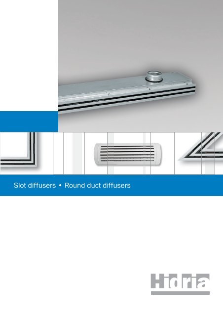
SLOT DIFFUSERS, ROUND DUCT DIFFUSERS<br />
Slot diffusers LD-13, LD-14, LD-15<br />
LD-13<br />
LD-14<br />
LD-15<br />
SLOT DIFFUSERS<br />
Application:<br />
Slot diffusers are designed for air supply in rooms<br />
with floor to ceiling heights of 2.5 to 4 m. They<br />
are suitable for supplying either cold or warm air,<br />
in particular in applications where air conditioning<br />
comfort demands are stringent. Due to their high<br />
induction rate and rapid decrease of temperature<br />
difference, these diffusers are also suitable for<br />
variable systems.<br />
Description:<br />
Diffuser face plate is made of anodized aluminium<br />
sections with built-in cylindrical deflectors made<br />
of recycled plastics. Deflectors allow continuos<br />
adjustment of discharged air direction within the<br />
360 o range. The diffuser plenum box is made of<br />
galvanised sheet steel and has a flow rate control<br />
damper built in its inlet spigot, to allow fine<br />
adjustment of the desired air flow rate.<br />
LD-16N<br />
Panel design slot diffusers LDP-13 and LDP-14<br />
LDP-14<br />
Round duct diffusers SKD-13<br />
SKD-13D<br />
Software: Klima ADE 5.3<br />
LD and SKD Software<br />
PANEL DESIGN SLOT DIFFUSERS<br />
A panel design slot diffuser consists of a face<br />
plate and a plenum box. Cylindrical air deflectors,<br />
equal to those in LD-13 and LD-14 diffusers,<br />
are installed in the slots, to allow continuous<br />
adjustment of discharged air direction within the<br />
360 o range. On order, diverse plate designs and<br />
slot patterns are available.<br />
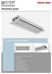
ROUND DUCT DIFFUSERS<br />
Application:<br />
Round duct diffusers can be installed at various<br />
locations within the duct network. They are suitable<br />
for supplying either cold or warm air.<br />
Description:<br />
They are made of galvanised tubes with slots<br />
equipped with cylindrical air deflectors equal<br />
to those in the LD-13 slot diffuser, to allow<br />
adjustment of air direction and flow rate. As<br />
standard, the tube and cylindrical deflectors are<br />
in RAL 9010 white colour.<br />
SOFTWARE: KLIMA ADE 5.3<br />
LD and SKD Software:<br />
- available calculation and graphical display of air<br />
supply for slot diffusers LD-13, LD-14 and LD-15<br />
- available calculation of technical specifications<br />
for the application of wall- or ceiling-mounted<br />
slot diffusers<br />
- available calculation of ceiling-mounted<br />
multiple-diffuser configuration air supply<br />
- application of vertical or horizontal slot diffuser<br />
air supply into the room, depending on the<br />
mode of operation - heating or cooling<br />
- the package supports basic air supply mode<br />
models for the SKD-13 round duct diffuser<br />
- available calculation of SKD-13 round duct<br />
diffusers<br />
cooling mode: single-side and two-side<br />
horizontal supply and alternating horizontal supply<br />
heating mode: vertical air supply
AIR DISTRIBUTION<br />
Slot diffusers, Round duct diffusers<br />
Slot diffusers<br />
Page<br />
Slot diffusers LD-13 and LD-14 ............................................................................................................................................................................................162<br />
Technical data for Slot diffusers LD-13 and LD-14 ...........................................................................................................................................................168<br />
Slot diffusers LD-15 ..............................................................................................................................................................................................................175<br />
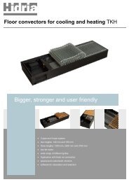
Floor slot diffusers LD-16N...................................................................................................................................................................................................179<br />
Panel design slot diffusers LDP-13, LDP-14.........................................................................................................................................................................181<br />
Round duct diffusers<br />
Round duct diffusers SKD-13................................................................................................................................................................................................183<br />
Legend of symbols<br />
St<br />
RAL<br />
9010<br />
Element is made of aluminium profiles, aluminium sheet or aluminium casting.<br />
Element is made of steel sheet.<br />
Element is powder painted in standard RAL 9010 colour. Other desired colour is to be specified in the order.<br />
Shady symbol means possibility of optional material, surface protection, motor version, ...<br />
Element is intended to be built in the floor.<br />
Element is intended to be built in the wall.<br />
Element is intended to be built in the ceiling or in the wall.<br />
Element for air conditioning of rooms with floor to ceiling heights room up to 4m.<br />
Element for air conditioning of rooms with floor to ceiling heights from 6 to 15m.<br />
Element is suitable for the supply of warm air (heating).<br />
M<br />
CD<br />
Element is suitable for the supply of cool air (cooling).<br />
Element allows regulation by electric motor (Belimo electric motors).<br />
Element is intended for air filtration. The filter of class ... is built in.<br />
The possibility of the automatic selection and calculation of the technical characteristics of grilles and difusers in regard to the given<br />
conditions with the assistance of the Klima ADE program.
SLOT DIFFUSERS LD-13, LD-14<br />
LD-13<br />
LD-14<br />
RAL<br />
CD<br />
Slot diffusers LD-13, LD-14<br />
Application:<br />
LD-13 and LD-14 slot diffusers are designed for<br />
the supply of air in rooms with floor to ceiling<br />
heights of 2.5 to 4 m for supplying either cold or<br />
warm air, in particular in applications where air<br />
conditioning comfort demands are stringent. Due<br />
to their high induction rate and rapid decrease<br />
of temperature difference, these diffusers are also<br />
suitable for variable systems.<br />
Description:<br />
LD-13 and LD-14 slot diffusers are designed in 1,<br />
2, 3 and 4-slot versions. Diffuser face plate<br />
consists of anodised aluminium sections with<br />
built-in cylindrical deflectors made of recycled<br />
plastics. Deflectors allow continuos adjustment<br />
of discharged air direction within the 360 o range<br />
as well as control of supply air flow rate. The<br />
cylindrical deflectors also allow full shutting of<br />
the diffuser. The slot diffuser plenum box is made<br />
of galvanised sheet steel and has a flow rate<br />
control damper built in its inlet spigot, to allow<br />
fine adjustment of the desired air flow rate.<br />
B 60<br />
1<br />
2<br />
3<br />
φ D<br />
H<br />
H1<br />
41<br />
8.5<br />
LD-13<br />
9.4<br />
5<br />
6<br />
Component parts:<br />
1 Plenum box<br />
2 Inlet spigot<br />
3 Volume control damper<br />
4 Main section<br />
5 Cylindrical deflector<br />
6 Side lateral section<br />
7 Connecting section<br />
8 Outside insulation<br />
15<br />
A<br />
E<br />
7<br />
a<br />
Installation openings:<br />
(A+5) x (L+15)<br />
Control schematic of the spigot volume<br />
control damper:<br />
8<br />
LD-14<br />
9.4 4<br />
53<br />
8.5<br />
5<br />
6<br />
26<br />
A 7<br />
E<br />
Installation openings:<br />
(A+5) x (L+15)<br />
162
SLOT DIFFUSERS LD-13, LD-14<br />
LD-13/1<br />
LD-14/1<br />
LD-13/2 LD-13/3 LD-13/4<br />
LD-14/2 LD-14/3 LD-14/4<br />
Slot diffuser types:<br />
• Single-slot (designation LD-13,14/1)<br />
• Two slots (designation LD-13,14/2)<br />
• Three-slots (designation LD-13,14/3)<br />
• Four-slots (designation LD-13,14/4)<br />
LD-13 O/1<br />
LD-13 O/2<br />
LD-13 O/3<br />
41.5<br />
41.5<br />
41.5<br />
37.5<br />
72.5<br />
LD-14 O/1<br />
LD-14 O/2<br />
LD-14 O/3<br />
53.5 53.5<br />
53.5<br />
50<br />
96.5<br />
Slot diffusers LD-13 O and LD-14 O<br />
Narrow version - New installation method<br />
The narrow slot diffuser differs from the<br />
conventional slot diffuser construction as<br />
regards its mounting to the ceiling or wall.<br />
The conventional slot diffuser has a L-crosssection<br />
mounting sleeve which remains<br />
visible and may, in certain applications, interfere<br />
with aesthetic requirements. The new design has<br />
eliminated this deficiency as well as introduced<br />
improved structural rigidity due to its reinforced<br />
sleeve. The product is thus suitable for<br />
installation in cooling suspended ceilings as well.<br />
107<br />
142<br />
LD-13 O/4<br />
41.5<br />
LD-14 O/4<br />
53.5<br />
142<br />
187.5<br />
LD-13 O, LD-14 O<br />
LD-13, LD-14<br />
LD-13<br />
No. of slots H H1 B A E F<br />
1 220 261 95 33 57.5 24.4<br />
2 230 271 129 67 92 58.2<br />
3 250 291 162 101 126.5 92.0<br />
4 290 331 196 135 161.5 125.8<br />
LD-14<br />
No. of slots H H1 B A E F<br />
1 233.5 287 106 44 69 35.3<br />
2 253.5 307 150 89 115 80<br />
3 293.5 347 195 133 161.5 124.7<br />
4 318.5 372 240 178 206.5 169.4<br />
Standard lenghts L<br />
LD-13 and LD-14 slot diffusers are available<br />
in standard lengths ranging from L=300 to<br />
L=2000 mm, with a 100 mm step. In cases where<br />
longer diffusers are required, they can be joint<br />
together by means of (rail-type) connecting plates.<br />
Plenum boxes are also available in standard<br />
lengths ranging from 300 mm to 2000 mm.<br />
Special orders:<br />
On customer’s request slot diffusers can be made<br />
in other dimensions. End seals and longitudinal<br />
sections are painted in any RAL scale colour<br />
according to the customer’s request. As standard,<br />
cylindrical deflectors are black or white, on the<br />
customer’s request, they can be coloured in any<br />
RAL scale colour. Non-standard colours and extra<br />
components are to be ordered separately.<br />
163
SLOT DIFFUSERS LD-13, LD-14<br />
L 300 to 1000 1100 to 1500 1600 to 2000<br />
Number<br />
Number and diameter of inlet spigots<br />
of slots LD-13 LD-14 LD-13 LD-14 LD-13 LD-14<br />
1 1 x 98 1 x 123 2 x 98 2 x 123 2 x 123 2 x 138<br />
2 1 x 138 1 x 158 2 x 123 2 x 138 2 x 138 2 x 158<br />
3 1 x 158 1 x 198 2 x 138 2 x 158 2 x 158 2 x 198<br />
4 1 x 198 1 x 223 2 x 158 2 x 198 2 x 198 2 x 223<br />
Number and diameter of inlet spigots<br />
Standard lenghts: from 300 mm to 1000 mm<br />
Number of slots: 1<br />
Standard lenghts: from 1000 mm to 2000 mm<br />
Number of slots: 2<br />
J<br />
L/2<br />
L/2<br />
J<br />
Position of inlet spigots:<br />
Number Standard Position<br />
of inlet spigots length of spigots<br />
1 300 - 1000 L/2<br />
2 1100 - 1500 J = 300<br />
2 1600 - 2000 J = 400<br />
angle 90˚<br />
300<br />
Slot diffuser face plate designs:<br />
Slot diffuser face plates are made of linear or<br />
angular ended sections, which allow the diffusers<br />
to be joined at different angles Angular ended<br />
sections are not fitted with air direction controls.<br />
300<br />
Cylindrical deflectors:<br />
Cylindrical deflectors are the most important<br />
components of a slot diffuser. They allow<br />
adjustment of both air flow rate and direction.<br />
Cylindrical deflectors are made of recycled<br />
plastics. As standard, they are black or white.<br />
End seals<br />
End seals are components of the diffuser face plate.<br />
They are available in two designs:<br />
• as an angle piece (E – on both ends, ET – on<br />
one end only) or<br />
• plates (F – on both ends, FT – on one end<br />
only).<br />
The connecting strip-section has no end angle<br />
pieces or plates seals (designation T).<br />
Joining diffusers together in length<br />
and width<br />
Joining in width (into diffusers with multiple<br />
slots) requires special strip sections, while joining<br />
in length requires connecting plates (the total<br />
length of combined diffusers is not limited).<br />
164
SLOT DIFFUSERS LD-13, LD-14<br />
Fixing of the plenum box onto LD-13,<br />
LD-14 diffusers<br />
• with self-tapping screws (designation U)<br />
• with spring clamps (designation S)<br />
• with a cross-member (designation Z)<br />
Fixing with self-tapping<br />
screws (U)<br />
Fixing with spring<br />
clamps (S)<br />
Fixing with<br />
a cross-member (Z)<br />
Installation methods:<br />
• with a threaded bar (designation R)<br />
• with a wire (designation R)<br />
• with suspension brackets on the plenum box<br />
(designation P)<br />
• with special fixing elements (designation R)<br />
• with springs (designation N)<br />
Installation with<br />
a threaded bar (R)<br />
Installation with wire (R)<br />
Installation with<br />
suspension bracket (P)<br />
Installation with special<br />
fastening elements (R)<br />
Installation with springs<br />
into ducts (N)<br />
165
SLOT DIFFUSERS LD-13, LD-14<br />
Types of air discharge<br />
a<br />
b<br />
LD-13<br />
Discharge direction<br />
Min. air flow rate<br />
Max. air flow rate<br />
Standard<br />
(left, right)<br />
Standard<br />
(right)<br />
c<br />
d<br />
101ß<br />
Discharge angle<br />
LD-14<br />
Standard<br />
(left)<br />
Standard<br />
(vertical)<br />
Discharge direction<br />
Min. air flow rate<br />
Max. air flow rate<br />
e<br />
f<br />
g<br />
Air jet angle 60 o<br />
(left, right)<br />
Air jet angle 60 o<br />
(right)<br />
Air jet angle 60 o<br />
(left)<br />
Discharge angle<br />
Top view<br />
Slot diffuser with actuator controlled<br />
discharge direction<br />
Slot diffusers with actuator controlled discharge<br />
direction are suitable for summer-winter air<br />
supply applications. The desired direction of air<br />
jet is achieved by means of an electric actuator<br />
which moves a slider. Manual adjustment is<br />
therefore not necessary. Compared with standard<br />
slot diffusers, air flow rate is reduced by 50 %.<br />
Component Parts:<br />
1 Slot diffuser<br />
2 Deflector<br />
3 Electric actuator<br />
In case the discharge angle is to be adjustable<br />
by means of an electric actuator (winter-summer<br />
application), this requirement shall be specified<br />
in the ordering form.<br />
Every second row<br />
1 Adjustment of deflectors for warm air supply<br />
Every second row<br />
2 Adjustment of deflectors for cold air supply<br />
166
SLOT DIFFUSERS LD-13, LD-14<br />
Ordering key:<br />
LD-13/1/B/E/K/M/S/P/I/g L=1700<br />
I5<br />
I9<br />
I19<br />
N<br />
P<br />
R<br />
Z<br />
S<br />
U<br />
Length L=300, 400, 500, ..., 2000 (single piece)<br />
Type of air discharge (a, b, c, d, e, f, g)<br />
Thermal insulation (polyethylene), 5 mm thick, on the outside of the plenum box.<br />
sound and thermal insulation (from -40 o C to 105 o C), 9 mm thick, on the outside of the plenum box<br />
(synthetic rubber based material).<br />
sound and thermal insulation (from -40 o C to 105 o C), 19 mm thick, on the outside of the plenum box<br />
(synthetic rubber based material).<br />
Installation with spring clamps – without plenum box (LD-13 and LD-14 only)<br />
Installation of the plenum box with hangers<br />
Installation with brackets built in the basic section<br />
Fixing of the diffuser to the plenum box with a cross-member<br />
Fixing of the diffuser to the plenum box with spring clamps<br />
Fixing of the diffuser to the plenum box with self-tapping screws<br />
M<br />
K<br />
Volume control damper<br />
Plenum box<br />
E<br />
ET<br />
F<br />
FT<br />
T<br />
B<br />
W<br />
End sealing on both ends<br />
End sealing on one end<br />
End plate on both end<br />
End plate on one end<br />
Rail-type without end sealings and plates<br />
Black deflectors<br />
White deflectors<br />
1<br />
2<br />
3<br />
4<br />
LD-13<br />
LD-14<br />
LD-13 O<br />
LD-14 O<br />
Number of slots<br />
Slot diffuser<br />
Narrow slot diffuser<br />
• Please specify the deflector colour in your order.<br />
• Standard eloxal colour of the aluminium section is the original aluminium colour. Other colours shall<br />
be specified in the order.<br />
• For the LD-13 0 and LD-14 0 type, the following end seals are available: F, FT and T.<br />
• When installing in cooling ceilings, consult the manufacturer.<br />
• In the case the slot diffuser is ordered complete with plenum box, the air jet configuration is set<br />
as shown on the diagram on page 166.<br />
• Versions with insulation on the inside of the plenum box are also available.<br />
167
SLOT DIFFUSERS LD-13, LD-14 TECHNICAL DATA<br />
Fast selection diagram: L WA < 35 dB(A)<br />
4<br />
3<br />
Nr. of slots<br />
2<br />
1<br />
LD-13<br />
LD-14<br />
100 300 500 1000 1200<br />
Q(m 3 /hm)<br />
Technical specifications for one-slot<br />
diffuser, per meter of lenght,<br />
at horizontal discharge:<br />
A(m 2 ) Q(m 3 /h) L WA (dB)<br />
LD-13 0,0092 135 34<br />
LD-14 0,0136 210 28<br />
H1<br />
A<br />
L<br />
VH1<br />
ΔtH<br />
L<br />
x<br />
VL<br />
ΔtL<br />
L<br />
x<br />
VL<br />
ΔtL<br />
H1<br />
VH1<br />
ΔtH<br />
A<br />
L<br />
VL<br />
x<br />
ΔtL<br />
Q (m 3 /h)<br />
x (m)<br />
H (m)<br />
L (m)<br />
V L (m/s)<br />
Δt z (K)<br />
Δt L (K)<br />
Δp (Pa)<br />
L WA (db(A))<br />
v H1 (m/s)<br />
A, B (m)<br />
H1 (m)<br />
Air flow rate<br />
Horizontal distance to the wall<br />
Room height<br />
Throw distance (L=H1+x)<br />
Air velocity at the throw<br />
distance L<br />
Temperate difference between<br />
the supply and room air<br />
Difference between the core and<br />
room air temperature<br />
Pressure drop<br />
Sound power level<br />
Air velocity at the distance H1<br />
Distance between diffusers, in<br />
length and in width<br />
throw distance<br />
168
SLOT DIFFUSERS LD-13, LD-14 TECHNICAL DATA<br />
Air velocity diagrams for LD-13, at different throw distances:<br />
One or two sided horizontal discharge:<br />
H1 (m)<br />
1 1.2 1.6 2<br />
LD-13 / 1 160 125 110 90 70 55 45<br />
LD-13 / 2 230 180 155 125 100<br />
LD-13 / 3 280 220 185 155<br />
LD-13 / 4 325 250 215 180<br />
2.5<br />
LD-13 / 1 160 125 110 90 70 55 45<br />
LD-13 / 2 230 180 155 125 100<br />
LD-13 / 3 280 220 185 155<br />
LD-13 / 4 325 250 215 180<br />
0.8<br />
V H1 (m/s)<br />
0.4<br />
0.3<br />
0.25<br />
0.2<br />
V (m/s)<br />
L<br />
0.6<br />
0.5<br />
0.4<br />
0.3<br />
0.25<br />
0.2<br />
0.15<br />
2 2.5 3 4 5 7 10<br />
A (m)<br />
0.15<br />
0.1<br />
2 2.5 3 4 5 7 10<br />
L (m)<br />
Alternate sided horizontal discharge:<br />
H1 (m)<br />
1 1.2 1.6 2<br />
LD-13 / 1 160 125 110 90 70 55 45<br />
LD-13 / 2 230 180 155 125 100<br />
LD-13 / 3 340 280 220 185 155<br />
LD-13 / 4 395 325 250 215 180<br />
2.5<br />
LD-13 / 1 160 125 110 90 70 55 45<br />
LD-13 / 2 230 180 155 125 100<br />
LD-13 / 3 340 280 220 185 155<br />
LD-13 / 4 395 325 250 215 180<br />
0.7<br />
V H1 (m/s)<br />
0.3<br />
0.25<br />
0.2<br />
0.15<br />
0.1<br />
V (m/s)<br />
L<br />
0.5<br />
0.4<br />
0.3<br />
0.25<br />
0.2<br />
0.15<br />
0.1<br />
2 2.5 3 4 5 7 10<br />
A (m)<br />
0.05<br />
2 2.5 3 4 5 7 10<br />
L (m)<br />
169
SLOT DIFFUSERS LD-13, LD-14 TECHNICAL DATA<br />
Air velocity diagrams for LD-14, at different throw distances:<br />
One or two sided horizontal discharge:<br />
H1 (m)<br />
1 1.2 1.6 2<br />
LD-14 / 1 160 125 110 90 70 55 45<br />
LD-14 / 2 230 180 155 125 100<br />
LD-14 / 3 280 220 185 155<br />
LD-14 / 4 325 250 215 180<br />
2.5<br />
LD-14 / 1 160 125 110 90 70 55 45<br />
LD-14 / 2 230 180 155 125 100<br />
LD-14 / 3 280 220 185 155<br />
LD-14 / 4 325 250 215 180<br />
V H1 (m/s)<br />
0.4<br />
0.3<br />
0.25<br />
0.2<br />
V L (m/s)<br />
0.8<br />
0.6<br />
0.5<br />
0.4<br />
0.3<br />
0.25<br />
0.2<br />
0.15<br />
2 2.5 3 4 5 7 10<br />
A (m)<br />
0.15<br />
0.1<br />
2 2.5 3 4 5 7 10<br />
L (m)<br />
Alternate sided horizontal discharge:<br />
H1 (m)<br />
1 1.2 1.6 2<br />
LD-14 / 1<br />
LD-14 / 2<br />
160<br />
230<br />
125 110 90<br />
180 155 125<br />
70<br />
100<br />
55 45<br />
LD-14 / 3 340 280 220 185 155<br />
LD-14 / 4 395 325 250 215 180<br />
2.5<br />
LD-14 / 1<br />
LD-14 / 2<br />
160<br />
230<br />
125<br />
180<br />
110 90<br />
155 125<br />
70<br />
100<br />
55 45<br />
LD-14 / 3 340 280 220 185 155<br />
LD-14 / 4 395 325 250 215 180<br />
V H1 (m/s)<br />
0.3<br />
0.25<br />
0.2<br />
0.15<br />
0.1<br />
V (m/s)<br />
L<br />
0.7<br />
0.5<br />
0.4<br />
0.3<br />
0.25<br />
0.2<br />
0.15<br />
0.1<br />
2 2.5 3 4 5 7 10<br />
A (m)<br />
0.05 2 2.5 3 4 5 7 10<br />
L (m)<br />
170
p (Pa)<br />
t<br />
SLOT DIFFUSERS LD-13, LD-14 TECHNICAL DATA<br />
Sound power level and pressure drop:<br />
200<br />
100<br />
50<br />
20<br />
15<br />
10<br />
8<br />
6<br />
4<br />
3<br />
2<br />
1.5<br />
LD 13/1 LD 13/2<br />
20<br />
25<br />
30<br />
35<br />
40<br />
500<br />
L wA (dB(A) )<br />
45<br />
50<br />
55<br />
1000<br />
1500<br />
2000<br />
p<br />
t<br />
(Pa)<br />
200<br />
100<br />
50<br />
20<br />
10<br />
8<br />
6<br />
4<br />
3<br />
2<br />
1.5<br />
10<br />
15<br />
20<br />
L wA (dB(A) )<br />
25<br />
30<br />
35<br />
40<br />
500<br />
60<br />
55<br />
50<br />
45<br />
1000<br />
1500<br />
2000<br />
1 100 150 200 300 400 500 700 1000<br />
Q (m 3 /h)<br />
1 100 150 200 300 400 500 700 1000<br />
Q (m 3 /h)<br />
Correction factors applicable to LD-13/1<br />
Type of discharge vertical horizontal<br />
Flow rate control damper open closed open closed<br />
L=500 x 1 x 1,44 x 0,87 x 1,34<br />
L=1000 x 1 x 3,30 x 0,85 x 3,02<br />
L=1500 x 1 x 5,26 x 0,84 x 4,47<br />
L=2000 x 1 x 7,37 x 0,81 x 5,68<br />
Correction factors applicable to LD-13/2<br />
Type of discharge vertical horizontal<br />
Flow rate control damper open closed open closed<br />
L=500 x 1 x 1,91 x 0,86 x 1,79<br />
L=1000 x 1 x 5,91 x 0,70 x 5,31<br />
L=1500 x 1 x 9,88 x 0,58 x 8,67<br />
L=2000 x 1 x 14,10 x 0,47 x 11,99<br />
Example:<br />
Q = 150 m 3 /h<br />
L = 1000 mm<br />
Δp t = 14 Pa (vertical; damper closed)<br />
Δp t = 14 x 3,30 = 46,2 Pa (vertical; damper closed)<br />
Δp t = 14 x 0,85 = 11,9 Pa (horizontal; damper opened)<br />
Δp t = 14 x 3,02 = 42,3 Pa (horizontal; damper closed)<br />
L WA = 32 dB(A)<br />
Example:<br />
Q = 150 m 3 /h<br />
L = 500 mm<br />
Δp t = 22 Pa (vertical; damper opened)<br />
Δp t = 22 x 1,91 = 42,0 Pa (vertical; damper closed)<br />
Δp t = 22 x 0,86 = 18,9 Pa (horizontal; damper opened)<br />
Δp t = 22 x 1,79 = 39,4 Pa (horizontal; damper closed)<br />
L WA = 30 dB(A)<br />
171
p (Pa)<br />
t<br />
t<br />
SLOT DIFFUSERS LD-13, LD-14 TECHNICAL DATA<br />
Sound power level and pressure drop:<br />
LD 13/3 LD 13/4<br />
200<br />
100<br />
50<br />
20<br />
10<br />
8<br />
6<br />
LwA (dB(A) )<br />
20<br />
25<br />
30<br />
35<br />
500<br />
45<br />
40<br />
75<br />
70<br />
60<br />
50<br />
1000<br />
1500<br />
2000<br />
p (Pa)<br />
200<br />
100<br />
50<br />
20<br />
10<br />
8<br />
6<br />
L wA (dB(A) )<br />
20<br />
25<br />
30<br />
35<br />
40<br />
500<br />
45<br />
55<br />
50<br />
1000<br />
1500<br />
2000<br />
4<br />
3<br />
2<br />
1.5<br />
1<br />
10<br />
15<br />
100 150 200 300 400 500 700 1000<br />
Q (m 3 /h)<br />
4<br />
15<br />
3<br />
2<br />
10<br />
1.5<br />
1<br />
100 150 200 300 400 500 700 1000<br />
Q (m 3 /h)<br />
Correction factors applicable to LD-13/3<br />
Type of discharge vertical horizontal<br />
Flow rate control damper open closed open closed<br />
L=500 x 1 x 2,37 x 0,84 x 2,24<br />
L=1000 x 1 x 8,52 x 0,56 x 7,59<br />
L=1500 x 1 x 14,50 x 0,32 x 12,86<br />
L=2000 x 1 x 20,82 x 0,18 x 18,29<br />
Correction factors applicable to LD-13/4<br />
Type of discharge vertical horizontal<br />
Flow rate control damper open closed open closed<br />
L=500 x 1 x 3,08 x 0,70 x 2,91<br />
L=1000 x 1 x 11,07 x 0,47 x 9,87<br />
L=1500 x 1 x 18,85 x 0,27 x 16,72<br />
L=2000 x 1 x 27,07 x 0,15 x 23,78<br />
Example:<br />
Q = 300 m 3 /h<br />
L = 1000 mm<br />
Δp t = 15 Pa (vertical; damper opened)<br />
Δp t = 15 x 8,52 = 127,8 Pa (vertical; damper closed)<br />
Δp t = 15 x 0,56 = 128,4 Pa (horizontal; damper opened)<br />
Δp t = 15 x 7,59 = 113,8 Pa (horizontal; damper closed)<br />
L WA = 29 dB(A)<br />
Example:<br />
Q = 300 m 3 /h<br />
L = 500 mm<br />
Δp t = 35 Pa (vertical; damper opened)<br />
Δp t = 35 x 3,08 = 107,8 Pa (vertical; damper closed)<br />
Δp t = 35 x 0,70 = 024,5 Pa (horizontal; damper opened)<br />
Δp t = 35 x 2,91 = 101,8 Pa (horizontal; damper closed)<br />
L WA = 33 dB(A)<br />
172
SLOT DIFFUSERS LD-13, LD-14 TECHNICAL DATA<br />
Sound power level and pressure drop:<br />
t<br />
t<br />
p (Pa)<br />
200<br />
100<br />
50<br />
20<br />
10<br />
8<br />
6<br />
4<br />
3<br />
2<br />
1.5<br />
1<br />
LD 14/1<br />
15<br />
L wA (dB(A) )<br />
20<br />
25<br />
30<br />
35<br />
100 150 200 300 400 500 700 1000<br />
Q (m 3 /h)<br />
40<br />
45<br />
500<br />
50<br />
1000<br />
1500<br />
2000<br />
p (Pa)<br />
200<br />
100<br />
50<br />
20<br />
10<br />
8<br />
6<br />
4<br />
3<br />
2<br />
1.5<br />
1<br />
LD 14/2<br />
LwA (dB(A) )<br />
15<br />
20<br />
25<br />
30<br />
100 150 200 300 400 500 700 1000<br />
Q (m 3 /h)<br />
35<br />
40<br />
45<br />
500<br />
50<br />
1000<br />
1500<br />
2000<br />
Correction factors applicable to LD-14/1<br />
Type of discharge vertical horizontal<br />
Flow rate control damper open closed open closed<br />
L=500 x 1 x 1,81 x 0,76 x 1,31<br />
L=1000 x 1 x 3,83 x 0,42 x 3,23<br />
L=1500 x 1 x 5,80 x 0,28 x 5,11<br />
L=2000 x 1 x 7,87 x 0,19 x 7,07<br />
Correction factors applicable to LD-14/2<br />
Type of discharge vertical horizontal<br />
Flow rate control damper open closed open closed<br />
L=500 x 1 x 2,11 x 0,53 x 1,59<br />
L=1000 x 1 x 8,84 x 0,29 x 7,96<br />
L=1500 x 1 x 15,36 x 0,20 x 14,14<br />
L=2000 x 1 x 22,32 x 0,14 x 20,70<br />
Example:<br />
Q = 300 m 3 /h<br />
L = 1000 mm<br />
Δp t = 33 Pa (vertical; damper opened)<br />
Δp t = 33 x 3,83 = 126,4 Pa (vertical; damper closed)<br />
Δp t = 33 x 0,42 = 14,0 Pa (horizontal; damper opened)<br />
Δp t = 33 x 3,23 = 107,0 Pa (horizontal; damper closed)<br />
L WA = 38 dB(A)<br />
Example:<br />
Q = 300 m 3 /h<br />
L = 500 mm<br />
Δp t = 47 Pa (vertical; damper opened)<br />
Δp t = 47 x 2,11 = 99,2 Pa (vertical; damper closed)<br />
Δp t = 47 x 0,53 = 24,9 Pa (horizontal; damper opened)<br />
Δp t = 47 x 1,59 = 74,7 Pa (horizontal; damper closed)<br />
L WA = 36 dB(A)<br />
173
t<br />
t<br />
SLOT DIFFUSERS LD-13, LD-14 TECHNICAL DATA<br />
Sound power level and pressure drop:<br />
LD 14/3 LD 14/4<br />
200<br />
500<br />
200<br />
500<br />
p (Pa)<br />
100<br />
50<br />
20<br />
10<br />
8<br />
6<br />
4<br />
3<br />
2<br />
1.5<br />
1<br />
LwA (dB(A) )<br />
15<br />
20<br />
100 150 200 300 400 500 700 1000<br />
Q (m 3 /h)<br />
25<br />
30<br />
35<br />
40 45 50<br />
1000<br />
1500<br />
2000<br />
p (Pa)<br />
100<br />
50<br />
20<br />
LwA (dB(A) )<br />
10<br />
25<br />
8<br />
6<br />
5<br />
20<br />
4<br />
3<br />
2<br />
1.5<br />
15<br />
1<br />
100 150 200 300 400 500 700 1000<br />
Q (m 3 /h)<br />
30<br />
35<br />
40<br />
1000<br />
1500<br />
2000<br />
Correction factors applicable to LD-14/3<br />
Type of discharge vertical horizontal<br />
Flow rate control damper open closed open closed<br />
L=500 x 1 x 2,41 x 0,33 x 1,87<br />
L=1000 x 1 x 13,86 x 0,19 x 12,69<br />
L=1500 x 1 x 24,92 x 0,16 x 23,17<br />
L=2000 x 1 x 36,76 x 0,13 x 31,33<br />
Correction factors applicable to LD-14/4<br />
Type of discharge vertical horizontal<br />
Flow rate control damper open closed open closed<br />
L=500 x 1 x 3,14 x 0,28 x 2,43<br />
L=1000 x 1 x 18,02 x 0,15 x 16,50<br />
L=1500 x 1 x 32,34 x 0,13 x 28,12<br />
L=2000 x 1 x 47,79 x 0,10 x 39,63<br />
Example:<br />
Q = 600 m 3 /h<br />
L = 1000 mm<br />
Δp t = 18 Pa (vertical; damper opened)<br />
Δp t = 18 x 13,86 = 249,5 Pa (vertical; damper closed)<br />
Δp t = 18 x 0,19 = 3,4 Pa (horizontal; damper opened)<br />
Δp t = 18 x 12,69 = 228,4 Pa (horizontal; damper closed)<br />
L WA = 38 dB(A)<br />
Example:<br />
Q = 600 m 3 /h<br />
L = 500 mm<br />
Δp t = 70 Pa (vertical; damper opened)<br />
Δp t = 70 x 3,14 = 219,8 Pa (vertical; damper closed)<br />
Δp t = 70 x 0,28 = 19,6 Pa (horizontal; damper opened)<br />
Δp t = 70 x 2,43 = 170,1 Pa (horizontal; damper closed)<br />
L WA = 36 dB(A)<br />
174
SLOT DIFFUSERS LD-15<br />
Slot diffuser LD-15<br />
RAL<br />
Application:<br />
Slot diffuser LD-15 is designed to supply air in<br />
rooms with floor to ceiling heights from 2.5 to 4m.<br />
They are primarily designed for the supply of cold<br />
air in applications with high comfort demands.<br />
80<br />
60<br />
CD<br />
Description:<br />
LD-15 slot diffuser is of a one-slot construction.<br />
The diffuser face plate consists of aluminium<br />
sections with built-in cylindrical deflectors made<br />
of recycled plastics. Individually adjustable<br />
deflectors allow continuous adjustment of<br />
discharge angle within the 360 0 range, as well as<br />
adjustment of air flow rate. The diffuser air flow<br />
can be completely shut by means of the cylindrical<br />
deflectors. The plenum box is made of galvanised<br />
sheet steel.<br />
Component Parts:<br />
1 Plenum box<br />
2 Inlet spigot<br />
3 Main section<br />
4 Cylindrical air deflector<br />
205<br />
147<br />
2<br />
φ78<br />
No. of spigots<br />
1<br />
Standard lengths (L)<br />
300, 400, 500, 600, 700<br />
800, 900, 1000<br />
1100, 1200, 1300, 1400<br />
2 1500, 1600, 1700, 1800<br />
1900, 2000<br />
Position of inlet spigots<br />
41<br />
1<br />
3<br />
The positions of inlet spigots are equal to those of<br />
LD-13 and LD-14 slot diffusers. See diagram and<br />
table on page 164.<br />
7.5<br />
4<br />
Slot diffuser face plate designs<br />
Installation openings:15 x L (diffuser length)<br />
15<br />
Slot diffuser face plates are made of linear or<br />
angular ended sections, which allow the diffusers<br />
to be joined at different angles. Angular ended<br />
sections are not fitted with air direction controls.<br />
Cylindrical air deflectors<br />
Cylindrical deflectors are the most important components<br />
of a slot diffuser. They allow free adjustment<br />
of the air flow rate.<br />
Joining slot diffusers together in length<br />
Sections can be joint together by means of<br />
connecting plates. Total length of so joint sections<br />
is not limited.<br />
175
SLOT DIFFUSERS LD-15<br />
Fixing of the plenum box onto a LD-15 slot<br />
diffuser:<br />
• with self-tapping screws (designation U)<br />
• with spring clamps (designation S)<br />
Fixing of the diffuser to the plenum box<br />
with self-tapping screws (U)<br />
Fixing of the diffuser to the plenum box<br />
with a spring clamps (S)<br />
Installation methods:<br />
• Installation with suspension brackets on<br />
the plenum box (designation P)<br />
• Instalaltion with suspension brackets on the<br />
main section (designation R)<br />
Installation with suspension<br />
brackets on the plenum box (P)<br />
Installations with suspension bracket on the main section (R)<br />
Ordering key:<br />
LD-15/B/K/M/S/P/I L=1500<br />
I5<br />
I9<br />
I19<br />
P<br />
R<br />
Length L=300, 400, 500, 600 ..., 2000 (single piece)<br />
Thermal insulation (polyethylene), 5 mm thick, on the outside of the plenum box.<br />
Sound and thermal insulation (from -40 o C to 105 o C), 9 mm thick, on the outside<br />
of the plenum box (synthetic rubber based material).<br />
Sound and thermal insulation (from -40 o C to 105 o C), 19 mm thick, on the<br />
outside of the plenum box (synthetic rubber based material).<br />
Installation of the diffuser with suspension brackets on the plenum box<br />
Installation with suspension brackets on the main section<br />
• Please specify the deflector colour in your order.<br />
• Standard eloxal colour of the aluminium section<br />
is the original aluminium colour. Other colours<br />
shall be specified in the order.<br />
• When installing in cooling ceilings, consult the<br />
manufacturer.<br />
• Versions with insulation on the inside of the<br />
plenum box are also available.<br />
S<br />
U<br />
M<br />
K<br />
B<br />
W<br />
Fixing of the diffuser to the plenum box with a spring clamp<br />
Fixing of the diffuser to the plenum box with self-tapping screws<br />
Volume control damper<br />
Plenum box<br />
Black deflectors<br />
White deflectors<br />
176
SLOT DIFFUSERS LD-15 TECHNICAL DATA<br />
Fast selection diagram:<br />
L=2000<br />
Technical data:<br />
Free surface, per 1 m of length: A ef =0.004559 m 2 .<br />
Air flow rate per 1 m of length: Q=20-70 m 3 /hm.<br />
L=1500<br />
L=1000<br />
L WA
200<br />
100<br />
500<br />
t<br />
SLOT DIFFUSERS LD-15 TECHNICAL DATA<br />
Sound power level and pressure drop<br />
55<br />
1000<br />
1500<br />
1000<br />
p (Pa)<br />
50<br />
20<br />
Lwa (dB(A))<br />
35<br />
30<br />
45<br />
40<br />
50<br />
10<br />
6<br />
4<br />
3<br />
15<br />
20<br />
25<br />
2<br />
1.5<br />
1<br />
10 20<br />
10<br />
30 40 50 60 80 100 150 200 250<br />
Q (m 3 /h)<br />
α=0˚ α=45˚ α=90˚<br />
Q (m 3 /h) 100 150 200 100 150 200 100 150 200<br />
L=500 Data in the diagram +5 +7 +10 +15 +32 +35<br />
L=1000 Data in the diagram +10 +12 +15 +33 +62 +100<br />
L=1500 Data in the diagram +4 +4 +8 +32 +63 +106<br />
L=2000 Data in the diagram +1 +2 +3 +27 +55 +81<br />
ΔP t correction (in Pa) in cases of vertical<br />
discharge<br />
α = 0˚ Control damper in the inlet spigot is fully opened<br />
α = 45˚ Control damper in the inlet spigot is half opened<br />
α = 90˚ Control damper in the inlet spigot is fully closed<br />
α<br />
α=0˚ α=45˚ α=90˚<br />
Q (m 3 /h) 100 150 200 100 150 200 100 150 200<br />
L=500 Data in the diagram +5 +7 +5 +12 +28 +60<br />
L=1000 Data in the diagram +8 +25 +33 +29 +66 +116<br />
L=1500 Data in the diagram +4 +11 +14 +29 +63 +101<br />
L=2000 Data in the diagram +1 +5 +7 +23 +52 +87<br />
ΔP t correction (in Pa) in cases of inclined<br />
discharge<br />
α = 0˚ Control damper in the inlet spigot is fully opened<br />
α = 45˚ Control damper in the inlet spigot is half opened<br />
α = 90˚ Control damper in the inlet spigot is fully closed<br />
α<br />
178
FLOOR SLOT DIFFUSERS LD-16N<br />
RAL<br />
9010<br />
Floor Slot Diffusers LD-16N<br />
Application:<br />
LD-16N floor slot diffusers are a suitable solution<br />
for swimming pools and similar rooms with large<br />
glass surfaces and windows. They are designed for<br />
installation in the floor. Warm air is supplied in the<br />
upwards direction, towards the window. With<br />
appropriate dimensions, proper air supply is<br />
guaranteed, free of excessive draught or noise<br />
(L WA
FLOOR SLOT DIFFUSERS LD-16N INSTALLATION<br />
Installation method:<br />
max 0.2 m<br />
1<br />
2<br />
1 glass<br />
2 LD 16N slot diffuser<br />
3 air supply channel<br />
3<br />
Fast selection diagram:<br />
L wA < 35 dB(A); V ef =2,5 m/s; Δp t = 80 Pa/m<br />
25<br />
20<br />
LD-16 N /1<br />
v ef<br />
L D -16<br />
N/2<br />
L D -16 N/3<br />
L D -16N /4<br />
L D -16N /5<br />
Example<br />
The available floor area next to the glass surface<br />
is 15 m in length. The calculated supplied air flow<br />
rate is 4000 m 3 /h. From the diagram, the type:<br />
LD-16N/3 L=15m is selected.<br />
L D -16N/6<br />
15<br />
L (m)<br />
10<br />
Ordering key:<br />
5<br />
1000 2000 3000 4000 5000 6000 7000 8000<br />
Q (m 3 /h)<br />
LD-16N / 1 / L / n<br />
number of longitudinal sections (pieces)<br />
Q (m 3 /h)<br />
L WA (dB(A))<br />
Δp t (Pa)<br />
L (m)<br />
v ef (m/s)<br />
Air flow rate<br />
Sound power level<br />
Pressure drop<br />
Slot diffuser length<br />
Effective air velocity<br />
Single piece length (L = 200, 300,......2000)<br />
1<br />
2<br />
3<br />
4<br />
5<br />
6<br />
LD-16N<br />
Number of slots<br />
Floor slot diffuser<br />
Standard colour is RAL 9010.<br />
180
PANEL DESIGN SLOT DIFFUSERS LDP-13, 14<br />
St<br />
RAL<br />
Panel design slot diffusers LDP-13,<br />
LDP-14<br />
Application:<br />
Panel design slot diffusers are designed for the<br />
supply of air in rooms with floor to ceiling<br />
heights from 2.4 m to 4 m. They are suitable<br />
for supplying either cold or warm air.<br />
A<br />
Description:<br />
LDP-13 and LDP-14 consists of a diffuser face<br />
plate and a plenum box. The diffuser face plate is<br />
commonly made of sheet steel and its design<br />
can be suited to the customer’s requirements.<br />
Longitudinal guides, fitting tight to the sheet<br />
steel, are inserted in the diffuser face plate.<br />
Cylindrical deflectors, made of recycled plastics<br />
(ABS-antistatic) are installed in the guides, to<br />
allow free adjustment of both air jet discharge<br />
direction and flow rate. The number of slots per<br />
unit depends on the size of the unit. Diffuser face<br />
plate is powder painted in a RAL 9010 scale<br />
colour, or, on special orders, in other colours.<br />
The deflectors, equal to those of LD-13 or LD-14<br />
slot diffusers, are white or black as standard.<br />
The plenum box is made of galvanised sheet<br />
steel. It is fitted with a flow rate control damper,<br />
designed for fine air flow rate adjustment.<br />
1<br />
3<br />
Types:<br />
• LDP-13 m = 12 mm<br />
• LDP-14 m = 22 mm<br />
H<br />
9<br />
4<br />
2<br />
φ D<br />
Component parts:<br />
1 Plenum box<br />
2 Volume control damper<br />
3 Inlet spigot<br />
4 Cross member<br />
5 Diffuser face plate<br />
6 Guide<br />
7 Air deflector<br />
8 Spring clamp<br />
5 C3<br />
8<br />
7<br />
6<br />
Dimensions:<br />
LDP-13<br />
LDP-14<br />
Size C3 Slot length A φ D H No. of slots h No. of slots h<br />
400 395 300 370 198 320 8 25 6 40<br />
500 495 400 470 198 320 10 6<br />
25<br />
600 595 500 570 248 380 12 25 8<br />
40<br />
625 620 500 570 248 380 12 8<br />
181
PANEL DESIGN SLOT DIFFUSERS LDP-13, 14<br />
Special orders:<br />
On special order, we can deliver diffuser face<br />
plates of any design. The shape and dimensions<br />
are specified in agreement with the designer or<br />
customer.<br />
Technical data:<br />
Tecnical data are determined upon the definition<br />
of the shape, design, number of discharge slots<br />
and other factors.<br />
Fast flow rate<br />
determination (at L WA < 35 dB(A)):<br />
LPD-13: flow rate per 1 meter length ≈100m 3 /h<br />
LPD-14: flow rate per 1 meter length ≈150m 3 /h<br />
Ordering key:<br />
LDP-13/B/K/M/I<br />
Size 400<br />
I5<br />
I9<br />
I19<br />
M<br />
Size (400, 500, 600, 625)<br />
Thermal insulation (polyethylene), 5 mm thick, on the outside of the plenum box.<br />
sound and thermal insulation (from -40 o C to 105 o C), 9 mm thick, on the outside of the plenum box<br />
(synthetic rubber based material).<br />
sound and thermal insulation (from -40 o C to 105 o C), 19 mm thick, on the outside of the plenum box<br />
(synthetic rubber based material).<br />
Volume control damper<br />
K<br />
Plenum box<br />
B<br />
W<br />
LDP-13<br />
LDP-14<br />
Black deflectors<br />
White deflectors<br />
• Please specify the deflector colour in your order.<br />
• Versions with insulation on the inside of the plenum box are also available.<br />
182
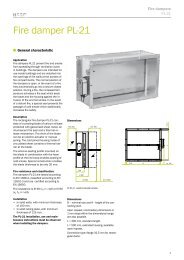
ROUND DUCT DIFFUSER SKD-13<br />
St<br />
RAL<br />
9010<br />
Round Duct Diffuser SKD-13<br />
Application:<br />
Round duct diffusers SKD-13 are designed for supplying air to the rooms<br />
with large floor to ceiling heights, e.g. conference halls, gyms, industrial<br />
halls etc. They can be installed at any location within the duct network,<br />
which renders them suitable for supplying of either hot or cold air.<br />
The T register model is designed to control the supply air flow-rate at the<br />
individual diffuser level. The T register design is recommended for<br />
installations with several round duct diffusers in one line. In such cases,<br />
the flow-rates of the diffusers near the line beginning should be slightly<br />
reduced, in order to supply adequate amounts of air to the diffusers<br />
farther along the line.<br />
Description:<br />
The duct diffuser consists of galvanised round cross-section tubes with<br />
inserted longitudinal guides, fitting tight into the tubes. Cylindrical<br />
deflectors made of recycled plastics are inserted into the guides, to allow<br />
continuous adjustment of discharged air direction within the 360 o range.<br />
Diffusers are available with different number of slots. The tube is painted in<br />
a RAL 9010 scale colour, or, on special orders, in other colours. The<br />
deflectors, equal to those of LD-13 slot diffusers, are white or black as<br />
standard.<br />
A T register, black in colour, is inserted in the SKD-13D/T. The T register<br />
is adjusted by means of a PVC knob, screwed onto a threaded bar.<br />
3 2 1<br />
Dimensions:<br />
φD/no.of 2 4 6 8 10 12 14<br />
Slots Slots Slots Slots Slots Slots Slots Slots<br />
150<br />
160<br />
180<br />
200<br />
225<br />
250<br />
280<br />
300<br />
315<br />
355<br />
400<br />
450<br />
500<br />
560<br />
600<br />
630<br />
710<br />
800<br />
900<br />
Components:<br />
1. SKD-13D<br />
2. T-register<br />
3. T-register adjusting knob<br />
L D L L V<br />
/ 1000 800<br />
1505 750 2 X 500<br />
1755 875 2 X 600<br />
2005 1000 2 X 800<br />
Diffuser structure for lengths exceeding 1000 mm:<br />
A<br />
D<br />
φ<br />
60 L v<br />
60<br />
L<br />
Note: φ D is the diffuser internal diameter.<br />
60<br />
Lv<br />
L<br />
5<br />
Ld<br />
Lv<br />
L<br />
60<br />
183
ROUND DUCT DIFFUSER SKD-13<br />
Accessories:<br />
End cover<br />
Ød<br />
Joining piece<br />
Ød<br />
Note: φd is the external diameter.<br />
40 40<br />
φD<br />
40 20<br />
7<br />
Elbow 90 0<br />
Ød<br />
L<br />
r<br />
7<br />
40<br />
Size d L,r<br />
150 148.7-149.3 150<br />
160 158.7-159.3 160<br />
180 178.6-179.3 180<br />
200 198.6-199.3 200<br />
224 222.5-223.3 224<br />
250 248.5-249.3 250<br />
280 278.4-279.3 280<br />
300 298.4-299.3 300<br />
315 313.4-314.3 315<br />
355 353.3-354.3 355<br />
400 398.3-399.3 400<br />
450 448.2-449.3 450<br />
500 498.2-499.3 500<br />
560 558.1-559.3 560<br />
630 628.1-629.3 630<br />
710 708.0-709.3 710<br />
800 798.1-799.3 800<br />
900 897.0-899.3 900<br />
Installation of SKD-13/D:<br />
SKD-13/D<br />
Joining<br />
piece<br />
Tube<br />
Joining<br />
piece<br />
SKD-13/D<br />
L<br />
87 L<br />
87<br />
L<br />
60<br />
SKD-13/R<br />
SKD-13/R is constructed for installations into round ducts with square<br />
openings.<br />
H<br />
L L v H No. of øD of tube Installation openings<br />
slots L-35 H-35<br />
580 500 100 1 150-355 545 65<br />
680 600 150 2 355-900 645 115<br />
880 800 200 3 600-2400 845 165<br />
880 800 250 4 600-2400 845 215<br />
L v<br />
L<br />
Installation of SKD-13/R:<br />
184
ROUND DUCT DIFFUSER SKD-13 TECHNICAL DATA<br />
Ordering key for SKD-13D:<br />
Ordering key for SKD-13R:<br />
SKD-13D /B /T /φ 355 /2 L=1000 mm<br />
SKD-13R /B /T /φ355 /2<br />
L=680 mm, H=150 mm<br />
length<br />
B<br />
W<br />
number of slots<br />
tube diameter<br />
T-register<br />
Black deflectors<br />
White deflectors<br />
tube<br />
length<br />
number of slots<br />
tube diameter<br />
T-register<br />
B Black deflectors<br />
W White deflectors<br />
R diffuser designed for<br />
installation into round<br />
ducts<br />
• Please specify the deflector colour in your order.<br />
Example accessory specification:<br />
Accessory: Elbow 90 0<br />
Colour: RAL 9010<br />
Quantity: 1 piece<br />
185
ROUND DUCT DIFFUSER SKD-13 TECHNICAL DATA<br />
Pressure drop determination diagram<br />
Fast selection diagram<br />
L WA<br />
< 35 dB(A)<br />
Number of slots<br />
2 4 6 8 10 12 14<br />
Example<br />
Air flow rate: Q=250 m 3 /h<br />
Nominal size:<br />
450 mm<br />
Appropriate number of slots is: 4<br />
φ150 - φ250<br />
φ280 - φ355<br />
Nominal φ<br />
Air velocity in the duct v(m/s)<br />
ΔP t (Pa)<br />
Q (m 3 /h)<br />
Nominal size φ mm<br />
φ400 - φ450<br />
φ500 - φ900<br />
125 250 375 500 625 750 825<br />
Air flow rate (m 3 /hm)<br />
186
ROUND DUCT DIFFUSER SKD-13 TECHNICAL DATA<br />
Pressure drop determination diagram<br />
v .......Air velocity in the duct<br />
Example 1<br />
Nominal size: φ 500 mm<br />
Number of slots: 6<br />
Air velocity in the duct: 4 m/s<br />
Flow rate through SKD: Q=450 m 3 /h<br />
Pressure drop: 15,5 Pa<br />
Example 2<br />
Max. pressure drop: 30 Pa<br />
Air velocity in the duct: 6 m/s<br />
Flow rate through SKD: Q=400 m 3 /h<br />
Unit to be chosen: SKD-13 φ400-900; n=8<br />
Pressure drop: 27 Pa; L WA
The right for technical changes reserved.<br />
188