cs outdoor solutions.pdf
cs outdoor solutions.pdf
cs outdoor solutions.pdf

Create successful ePaper yourself
Turn your PDF publications into a flip-book with our unique Google optimized e-Paper software.
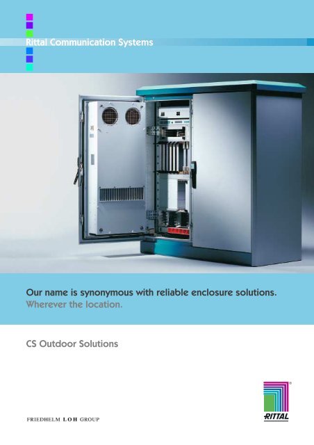
Rittal Communication Systems<br />
Our name is synonymous with reliable enclosure <strong>solutions</strong>.<br />
Wherever the location.<br />
CS Outdoor Solutions<br />
R
Overview of CS <strong>outdoor</strong> enclosures<br />
Wall-mounted<br />
Standard enclosures<br />
Individual<br />
■ 4 types<br />
■ Twin-walled (enclosure within an<br />
enclosure)<br />
■ Aluminium (AlMg3)<br />
■ Door and designer cover with<br />
security lock<br />
■ 482.6 mm (19”) rotating frame,<br />
fitted<br />
■ System integration up to Level 4<br />
Compact enclosures<br />
Standard enclosures<br />
■ 4 types<br />
■ Single-walled<br />
■ Aluminium (AlMg3) / aluminium<br />
zinc plate<br />
■ 3-point fastener with<br />
security lock<br />
Individual<br />
■ Shielding of the twin-door<br />
enclosure<br />
■ Lock concepts for shielded areas<br />
■ Roof-mounted heat exchanger for<br />
1,100 mm wide enclosures<br />
Basic enclosures<br />
Standard enclosures<br />
■ 16 types<br />
■ Single-walled<br />
■ Aluminium (AlMg3)<br />
3-point fastener with<br />
security lock<br />
Individual<br />
■ Installation service with system<br />
accessories<br />
■ Size variants<br />
Colour variants<br />
Modular enclosures<br />
Standard enclosures<br />
■ 4 types, pre-configured<br />
■ Twin-walled<br />
■ Aluminium (AlMg3) / aluminium<br />
zinc plate<br />
■ 3-point fastener with<br />
security lock<br />
Individual<br />
■ Installation service from the<br />
modular range with 12 frame sizes<br />
■ Climate control equipment (cooling<br />
units and air/air heat exchangers)<br />
Customised <strong>solutions</strong> - Size variants,<br />
baying variants, Level 4<br />
system integration<br />
CS Toptec<br />
Standard enclosures<br />
■ 8 types<br />
■ Twin-walled doors and panels<br />
■ Aluminium (AlMg3)<br />
■ Pre-configured with integral<br />
climate control solution<br />
Individual<br />
■ Size variants<br />
■ Baying variants<br />
Customised <strong>solutions</strong> - Level 4<br />
system integration<br />
2 Rittal CS Outdoor Solutions
The Rittal CS Solutions<br />
Contents<br />
Rittal’s expertise<br />
Flexibility<br />
Product diversity<br />
Security<br />
Knowledge transfer<br />
Globalisation<br />
Integrative thinking<br />
System concept<br />
4 – 5<br />
6 – 7<br />
8 – 9<br />
10 – 11<br />
12 – 13<br />
14 – 15<br />
16 – 17<br />
CS Outdoor wall-mounted<br />
enclosures<br />
CS Outdoor compact enclosures<br />
CS Outdoor basic enclosures<br />
CS Outdoor modular enclosures<br />
CS Outdoor climate control<br />
components<br />
Solution diversity<br />
Order information<br />
Solution diversity<br />
Order information<br />
Solution diversity<br />
Order information<br />
Solution diversity<br />
Order information<br />
Order matrix / detailed drawing<br />
Aluminium modular enclosure<br />
Order matrix / detailed drawing<br />
Aluminium zinc plate modular enclosure<br />
Roof-mounted heat exchanger<br />
Universal built-in heat exchanger<br />
Wall-mounted heat exchanger<br />
Door-mounted heat exchanger<br />
Roof-mounted cooling unit<br />
Universal built-in cooling unit<br />
Wall-mounted cooling unit<br />
Door-mounted cooling unit<br />
Rack-mounted fan<br />
Heaters<br />
18 – 19<br />
20 – 21<br />
22 – 23<br />
24 – 25<br />
26 – 27<br />
28 – 29<br />
30 – 31<br />
32 – 35<br />
36 – 39<br />
40 – 43<br />
44 – 45<br />
46 – 47<br />
e<br />
CS <strong>outdoor</strong> enclosures System accessories 48 – 53<br />
Indoor rack Order information 54 – 55<br />
Container/shelter<br />
Solution diversity<br />
Order information<br />
56 – 57<br />
58 – 59<br />
Terravent Order information 60 – 61<br />
CS Toptec<br />
Solution diversity<br />
Order information<br />
Accessories<br />
62 – 63<br />
64 – 65<br />
66 – 71<br />
EMC concept 72 – 73<br />
CFD thermographi<strong>cs</strong> 74 – 75<br />
Protection categories/dimensions/standards 76 – 77<br />
A – Z/Rittal international 78 – 79<br />
Rittal CS Outdoor Solutions 3
Flexibility Product diversity Security Knowledge transfer Globalisation Integrative thinking<br />
The possibilities of modern communications are limitless.<br />
4
System concept<br />
Ask the experts.<br />
Versatile <strong>outdoor</strong> <strong>solutions</strong>.<br />
e.g. for traffic guidance systems,<br />
telecommunications<br />
and information technology<br />
Communications technology is developing at a rapid pace. However sophisticated it becomes, one thing remains – the<br />
junctions through which information must pass securely. Here at Rittal Communication Systems, this is our speciality.<br />
We accommodate our customers’ requirements with solution diversity, whatever the application. We also respond flexibly<br />
to demands for expansion and modularity. This allows our customers to make plans for the future, safe in the knowledge<br />
that the possibilities are limitless.<br />
Telecommunications<br />
Versatile enclosure <strong>solutions</strong> for all<br />
applications where voice and data packages<br />
are around the globe, such as mobile<br />
phone base stations, point-to-multipoint<br />
networks and colocations.<br />
Information technology<br />
Versatile enclosure <strong>solutions</strong> for cable<br />
and telecommunications networks, for the<br />
reliable operation of junctions within the<br />
network.<br />
Traffic guidance systems<br />
Versatile enclosure <strong>solutions</strong> for<br />
recording speed, traffic transported<br />
density and toll fees, and for controlling<br />
traffic lights and applications, radio<br />
sign bridges.<br />
Rittal CS Outdoor Solutions 5
Flexibility Product diversity Security Knowledge transfer Globalisation Integrative thinking<br />
Customer requirements are many and varied. Just like our<br />
6
System concept<br />
product range.<br />
Diversity, from <strong>outdoor</strong><br />
to indoor:<br />
Wall-mounted enclosures,<br />
Compact enclosures,<br />
Basic enclosures,<br />
Modular enclosures,<br />
Toptec, Containers<br />
Indoor racks and<br />
Not only do our customers come from a diverse range of businesses; they also<br />
have very individual solution requirements. We accommodate their needs with<br />
a comprehensive selection of products, ranging from wall-mounted<br />
enclosures and compact enclosures, to modular enclosures and basic<br />
enclosures, through to indoor racks.<br />
Heat exchangers, cooling units, heaters and fans ensure the right climate<br />
inside the enclosure.<br />
As well as standard enclosure <strong>solutions</strong>, our range also includes individual<br />
configuration <strong>solutions</strong> and levels. With the right components and an extensive<br />
range of accessories, standard enclosures can be precisely tailored to your<br />
requirements and retrospectively upgraded. After all, planning confidence and<br />
flexibility are also key customer requirements.<br />
■ Wall-mounted enclosures<br />
■ Compact enclosures<br />
■ Basic enclosures<br />
■ Modular enclosures<br />
■ Toptec<br />
■ Containers<br />
■ Indoor racks<br />
■ Climate control units<br />
Rittal CS Outdoor Solutions 7
Flexibility Product diversity Security Knowledge transfer Globalisation Integrative thinking<br />
Our customers have certain security needs.<br />
8
System concept<br />
We offer uncompromising <strong>solutions</strong>.<br />
Maximum protection for your<br />
equipment. Tested to most<br />
major standards, including<br />
IEC, ETSI, Bellcore, Nema<br />
and UL.<br />
Our customers need to be sure that our enclosure <strong>solutions</strong> will withstand anticipated<br />
stresses and strains. When it comes to <strong>outdoor</strong> applications, our developments are<br />
designed to cope with the unexpected as well as the expected.<br />
It all starts with corrosion-resistant aluminium enclosures, and continues with insulation,<br />
EMC protection and access control. The CMC monitoring unit allows you to check power<br />
supply, unauthorised access, vibration, smoke generation, humidity and other parameters<br />
at the very highest level.<br />
Rittal Communication Systems have everything you need to protect your electronic<br />
equipment, from weather-tested enclosure <strong>solutions</strong>, to a variety of climate control<br />
components, through to complete security management systems. Anytime, anywhere.<br />
This is guaranteed by state-of-the-art computer simulation and extensive laboratory<br />
testing.<br />
Climate protection<br />
A wide range of components ensures the correct climate<br />
inside the enclosure, by controlling temperature and<br />
humidity.<br />
Corrosion protection<br />
The enclosure and climate control components are<br />
manufactured from powder-coated aluminium, which makes<br />
them resistant to UV and salt water.<br />
EMC protection<br />
Reduction and avoidance of emitted interference, thanks to<br />
chromate conversion treated enclosures, EMC seals and<br />
special earthing measures.<br />
Mechanical protection<br />
Protection against vandalism, earthquakes and other acts of<br />
violence, thanks to a robust frame structure or specially<br />
desgned surfaces with no points of access for would-be<br />
intruders.<br />
9
Flexibility Product diversity Security Knowledge transfer Globalisation Integrative thinking<br />
Information exchange is not a matter of time and place, but<br />
10
System concept<br />
of person to person.<br />
We are keen to maximise<br />
knowledge transfer - at trade<br />
fairs, conferences, symposia,<br />
committees, and regular & advanced<br />
training courses.<br />
Please note that our<br />
expertise is not confined<br />
to the products<br />
themselves, but also<br />
includes competent<br />
advice throughout every<br />
phase of the process,<br />
from start to finish.<br />
We realise how important knowledge is. That is<br />
why we are so keen to share it with our<br />
customers, the industry and our staff,<br />
wherever in the world they happen to be. That<br />
is why we are always moving forward, sharing<br />
our experiences from person to person.<br />
Trade fairs are the most important forum for knowledge transfer. As well as showcasing the latest products, these events<br />
are also ideal for sharing expertise. All the information gleaned is channelled into our future efforts, be it developing new<br />
products, advising customers, or providing advanced staff training. You know your trust in us is well-placed. And trust is<br />
the most important aspect of any relationship.<br />
Rittal CS Outdoor Solutions 11
Flexibility Product diversity Security Knowledge transfer Globalisation Integrative thinking<br />
Is your company a global player? If so, our paths are bound<br />
12 Rittal CS Outdoor Solutions
System concept<br />
to cross.<br />
19 factories, 40 subsidiaries and<br />
branch offices on 3 continents.<br />
Global distribution of more than 8,000<br />
standard products.<br />
Active involvement in standardisation<br />
committees.<br />
And much, much more besides.<br />
As global players, we draw on many years of experience in international markets.<br />
Our specific market knowledge benefits our customers and facilitates a finely-tuned distribution system.<br />
Wherever in the world you choose to develop and implement <strong>solutions</strong> for yourself and your customers, you can be sure<br />
that Rittal is close at hand.<br />
This is particularly true in markets which are governed by electroni<strong>cs</strong>. Our own branch offices, production sites, and<br />
partner companies are available to support your activities. We are also actively involved in key standardisation<br />
committees. Our 19 factories supply 40 subsidiaries and more than 70 branch offices.<br />
This extensive distribution network means that over 8,000 standard products are available to you anytime, anywhere.<br />
So you can rest assured that the right solution is always close at hand.<br />
13
Flexibility Product diversity Security Knowledge transfer Globalisation Integrative thinking<br />
Rittal supplies <strong>solutions</strong> from a single source. But we draw on<br />
14
System concept<br />
many different sources of expertise.<br />
All from Rittal.<br />
Everything our customers need:<br />
Electronic Systems<br />
IT Solutions<br />
CS Outdoor<br />
Industrial PCs<br />
and much, much more besides.<br />
We have a large range of enclosures available for immediate delivery. But<br />
that’s not all. Many years of involvement in a variety of market sectors have<br />
given us a wealth of expertise and enabled us to specialise. Our customers<br />
can benefit from this extensive know-how, in the form of integrated<br />
<strong>solutions</strong>. The principal concept behind our enclosures remains intact:<br />
Expertly designed protection with a wealth of ideas inside.<br />
Whether you require a terminal with touchscreen monitor for a theatre foyer,<br />
an <strong>outdoor</strong> enclosure with climate control technology for the desert<br />
landscapes of Dubai, a vibration damping electronic rack for high-speed<br />
trains, or a fold-out monitor/keyboard drawer for tough industrial environments,<br />
our <strong>solutions</strong> unite the entire expertise of all our divisions. Why not<br />
put Rittal to the test?<br />
■ Industrial Enclosures<br />
■ Electronic Packaging<br />
■ System Climate Control<br />
■ Power Distribution<br />
■ IT Solutions<br />
Rittal CS Outdoor Solutions 15
Flexibility Product diversity Security Knowledge transfer Globalisation Integrative thinking<br />
Our <strong>solutions</strong> have what it takes. Fully assembled and<br />
16
System concept<br />
integrated systems.<br />
Complete enclosure systems<br />
with components<br />
e.g. for:<br />
climate control,<br />
power supply,<br />
remote control and<br />
access protection.<br />
We don’t just talk about system integration – we supply<br />
it. And at a very high level (up to Level 4). This is the<br />
product of intensive consultation and scrupulous<br />
planning. The net result is a fully functional solution,<br />
exactly where you need it.<br />
As experienced enclosure manufacturers, we are familiar<br />
with our core business. Over the years, we have<br />
developed <strong>solutions</strong> which combine our entire expertise.<br />
Depending on the application area and the climatic and<br />
technical requirements, we install a pre-assembled and<br />
prewired framework for interior configuration of the<br />
enclosures. These can be supplied, for example, with a<br />
co-ordinated climate control package, power supply and<br />
security management through to Level 4 system<br />
integration. All this from a single source – Rittal.<br />
A closer look:<br />
Example of an enclosure combination for a wireless local loop<br />
(WLL) application.<br />
WLL enclosure<br />
System technology designed for data relay and receipt via radio:<br />
Fully configured with DC air/air heat exchanger, AC heater, and<br />
decentralised DC distributor, with fully connected system<br />
technology.<br />
Network enclosure<br />
Backbone connection. Likewise fully fitted with DC air/air heat<br />
exchanger, AC heater, and decentralised DC distributor.<br />
WLL enclosure<br />
Same functions and preconfiguration as for the modular enclosure<br />
on the far left.<br />
Power enclosure<br />
To supply other modular enclosures. Pre-configured with: DC air/air<br />
heat exchanger at the top or AC heater, AC distributor, DC power<br />
supply 48 V/DC max. 300 A / 14,400 W and battery backup for up<br />
to 4 hours as an emergency power supply.<br />
Pre-configured with:<br />
AC infeed, lightning and overvoltage protection, plus optional<br />
emergency power infeed.<br />
17
Wall-mounted enclosures at a glance:<br />
Standard enclosures<br />
■ 4 types<br />
■ Twin-walled concept (an enclosure within an<br />
enclosure)<br />
■ Aluminium (AlMg3)<br />
■ Door and designer cover with security lock<br />
Individual<br />
■ 482.6 mm (19”) rotating frame, fitted<br />
■ System integration up to Level 4<br />
Design features<br />
The enclosure-within-anenclosure<br />
concept with curved<br />
designer cover is a typical<br />
example.<br />
Security lock on the designer cover and door of the<br />
inner enclosure.<br />
Climate control<br />
Air louvres at the sides and in the rear panel.<br />
Particularly in <strong>outdoor</strong> use,<br />
condensation poses a special<br />
risk. Controlled enclosure heating<br />
helps to counteract this.<br />
Individual<br />
The entire power supply,<br />
including fuses, may be installed<br />
upon request.<br />
Optimum use of the interior space with system integration up to Level 4.<br />
System accessories<br />
Rotating frame for<br />
vertical mounting<br />
of 482.6 mm (19”)<br />
components.<br />
Fast, secure attachment of enclosures using the pole clamp or wall bracket.<br />
18 Rittal CS Outdoor Solutions
CS Outdoor wall-mounted enclosures<br />
A perfect design for perfect protection.<br />
he enclosure-within-an-enclosure<br />
CS Outdoor wall-mounted enclosures are<br />
based on the twin-walled concept - an<br />
enclosure within an enclosure. The<br />
impressive designer cover has a<br />
concealed fastener. The entire enclosure is<br />
manufactured from aluminium with<br />
additional powder coating, thus combining<br />
corrosion protection with eco-friendliness.<br />
Rittal offers a broad selection of options<br />
for individual interior installation.<br />
Our example:<br />
Here you can see an inner<br />
enclosure with separate<br />
lockable door. The outer<br />
enclosure forms the second<br />
“hard shell”. The above<br />
example is fitted with a<br />
complete power supply unit<br />
(sockets, fuses, power pack,<br />
climate control, earthing).<br />
Rittal CS Outdoor Solutions 19
Order information<br />
CS Outdoor wall-mounted enclosures<br />
Enclosures<br />
Width in mm, outer/inner 370/300 420/350 530/460 630/580<br />
Height in mm, outer/inner 522.5/400 560.5/440 700/565 780/580<br />
Depth in mm, outer/inner 210/170 210/170 265/220 380/333<br />
Model No. CS 9791.015 9791.025 9791.035 9791.045<br />
Page<br />
Accessories<br />
Wall mounting bracket (Packs of 4) CS 9765.120 9765.120 9765.120 9765.120 48<br />
Pole clamp CS 9765.125 9765.125 9765.125 9765.125 48<br />
Rotating frame, 482.6 mm (19”) CS – – – 9765.130 48<br />
Heater 30 W SK 3115.000 3115.000 3115.000 3115.000 –<br />
Thermostat SK 3110.000 3110.000 3110.000 3110.000 –<br />
View B<br />
182<br />
192<br />
52<br />
62<br />
T3<br />
Technical specifications/<br />
Enclosure material:<br />
Aluminium AlMg3<br />
Outer enclosure: 2.0 mm<br />
Inner enclosure: 1.5 mm/2.0 mm<br />
Doors: 2.0 mm<br />
Mounting plate:<br />
2.0 mm Aluminium AlMg3<br />
Surface finish of inner and outer<br />
enclosure:<br />
Enclosure and door(s):<br />
Powder coated in RAL 7035<br />
Mounting plate: Aluminium AlMg3,<br />
chromated<br />
Protection category of inner<br />
enclosure:<br />
IP 55 to EN 60 529/10.91<br />
Schließung SZ<br />
Supply includes:<br />
Mounting bracket<br />
for thermostat<br />
SK 3110.000<br />
Mounting plate B4<br />
Mounting plate H4<br />
The mounting plate may be<br />
mounted in the inner enclosure<br />
and internal door<br />
H2<br />
H1<br />
A<br />
H3<br />
M8<br />
H7<br />
16<br />
T4<br />
30<br />
H5<br />
15<br />
B2<br />
B1<br />
B<br />
1.5<br />
15<br />
Roof cutout of inner enclosure with gland plate:<br />
CS 9791.015 / .025 / .035W 97.5 x T 65.5<br />
CS 9791.045 W 302.0 x T 122.0<br />
8.6<br />
T2<br />
8.5<br />
T1 23<br />
15<br />
2749.000<br />
mit Sicherheits-Einsatz<br />
(ab B1 = 630 2 Schließungen)<br />
B1 = Width of outer enclosure<br />
B2 = Width of inner enclosure<br />
B3 = Centre-to-centre spacing of<br />
C rail attachment/inner enclosure.<br />
Centre-to-centre spacing<br />
to accommodate the wall<br />
mounting bracket<br />
B4 = Width of mounting plate<br />
H1 = Height of outer enclosure<br />
H2 = Height of inner enclosure<br />
H3 = Centre-to-centre spacing of<br />
C rail attachment/inner enclosure.<br />
Centre-to-centre spacing<br />
H4 = Height of mounting plate<br />
10 B3<br />
H4 = Height of mounting plate<br />
H5 = Distance from outer enclosure<br />
to C rail attachment/<br />
inner enclosure<br />
H7 = Distance from outer enclosure<br />
to inner enclosure<br />
T1 = Depth of outer enclosure<br />
T2 = Depth of inner enclosure<br />
T3 = Distance from outer enclosure<br />
to centre of bottom<br />
gland plate<br />
T4 = Distance from outer enclosure<br />
to centre of top gland<br />
plate<br />
10<br />
Model No. B1 B2 B3 B4 H1 H2 H3 H4 H5 H7 T1 T2 T3 T4<br />
CS 9791.015 370 300 260 270 522,5 400 360 380 57,5 37,5 210 170 55,5 72,5<br />
CS 9791.025 420 350 310 320 560 440 400 410 58 38 210 170 55,5 72,5<br />
CS 9791.035 530 460 420 430 700 565 525 535 63 43 265 220 82 72,5<br />
CS 9791.045 630 580 540 550 780 580 540 550 55 35 380 333 82 155<br />
20 Rittal CS Outdoor Solutions
Order information<br />
CS Outdoor wall-mounted enclosures<br />
Supply includes:<br />
Inner enclosure with door,<br />
aluminium mounting plate,<br />
security lock,<br />
foamed-in door seals,<br />
bottom gland plate,<br />
mounting bracket for thermostat,<br />
outer enclosure with integral<br />
ventilation louvres,<br />
designer cover with security lock,<br />
C rails.<br />
German utility model<br />
no. 297 16 467<br />
German registered design<br />
no. 97 08 625<br />
UK Registered Design<br />
no. 2 072 965<br />
IR Reg. Design no. DM/044 110<br />
with validity for ES, FR, IT, Indonesia<br />
US patent no. 6,024,236<br />
Rotating frame<br />
For vertical installation of<br />
482.6 mm (19”) assemblies.<br />
Model No. see page 48.<br />
Pole clamp<br />
For attaching to round or square<br />
poles.<br />
Model No. see page 48.<br />
Complete interior installation<br />
of the wall-mounted enclosure up<br />
to integration level 4 available to<br />
order.<br />
Rittal CS Outdoor Solutions 21
Compact enclosures at a glance:<br />
Standard enclosures<br />
■ 4 types<br />
■ Single-walled<br />
■ Aluminium (AlMg3) / aluminium zinc plate<br />
■ 3-point fastener with security lock<br />
Individual<br />
■ Shielding of the double-door enclosure<br />
■ Lock concepts for shielded areas<br />
■ Roof-mounted heat exchanger for 1,100 mm wide<br />
enclosures<br />
Design features<br />
Application diversity: The basic<br />
dimensions of the compact<br />
enclosures correspond to base/<br />
plinth dimensions KVz 83 and 84<br />
from Deutsche Telekom.<br />
Rain canopy for optimum<br />
weather protection.<br />
The enclosure may be lifted using<br />
eyebolts, for easy transportation.<br />
Interior installation<br />
Assembly-friendly: Remove the<br />
enclosure cover, quickly complete<br />
interior installation on the<br />
open mounting frame, slip the<br />
cover back over, screw fasten<br />
into position, and voila!<br />
The gland plates ensure a high<br />
degree of flexibility with cable<br />
entry.<br />
The standard mounting plate<br />
offers another alternative for the<br />
assembly of additional<br />
components.<br />
The Ergoform padlock handle<br />
system achieves security with a<br />
semi-cylinder.<br />
Climate control<br />
With the roof-mounted heat<br />
exchanger for 1,100 mm wide<br />
enclosures, the protection<br />
category of IP 55 is retained.<br />
Heater module as a fully wired<br />
unit, ready to connect, designed<br />
as a 482.6 mm (19”) rack mount<br />
with 3 thermal components and 3<br />
fan units.<br />
To prevent condensation,<br />
an enclosure heater should be<br />
installed.<br />
Individual<br />
Fully fitted with rail systems from the modular sytem; alternatively, the Computer Multi Control (CMC)<br />
monitoring system allows monitoring of safety-relevant parameters such as power supply, climate control,<br />
smoke generation and enclosure vibration.<br />
22 Rittal CS Outdoor Solutions
CS Outdoor compact enclosures<br />
A concept with a successful history.<br />
CS Outdoor compact enclosures are based on the<br />
successful Rittal AE series of compact enclosures, a<br />
concept which has been proven a million times over.<br />
At its core is the enclosure, manufactured from a single<br />
piece. This ensures a high level of stability in a compact<br />
format, whilst the PU seals foamed into the doors ensure a<br />
high level of protection. The all-round mounting frame with a<br />
25 mm pitch pattern of holes ensures perfect, individual<br />
interior installation. All matching accessory components<br />
from Rittal may be fitted here. For <strong>outdoor</strong> use, customers<br />
may choose between aluminium and aluminium zinc plate.<br />
Our example:<br />
The double-door compact enclosure with<br />
rain canopy and 100 mm high transport<br />
plinth. Complete with asymmetrically<br />
divided mounting plate and screw fastened<br />
mounting frame. Fully preconfigured for fast<br />
interior installation.<br />
Rittal CS Outdoor Solutions 23
Order information<br />
CS Outdoor compact enclosures<br />
Material Aluminium AlMg3 Aluminium zinc<br />
Enclosure Single-door Double-door Single-door Double-door<br />
Width in mm 800 1100 800 1100<br />
Height in mm 1100 1100 1100 1100<br />
Depth in mm 320 320 320 320<br />
Model No. CS 9771.115 9772.115 9771.110 9772.110<br />
Accessories Model No. CS<br />
Roof-mounted heat exchanger, 15 W/K – 9767.012 – 9767.012<br />
Rain canopy for roof-mounted heat exchanger – 9779.053 – 9779.004<br />
Roof-mounted version or enclosure (W = 1100 mm)<br />
with roof-mounted heat exchanger 15 W/K<br />
111<br />
1119<br />
337.5<br />
A<br />
B<br />
100<br />
1100 60<br />
20<br />
320<br />
66 200<br />
320<br />
46<br />
814<br />
760<br />
800<br />
Section A – A<br />
500<br />
113<br />
Section B – B<br />
700<br />
708<br />
800<br />
60 195<br />
21.5<br />
20<br />
1060 20<br />
13.5 168<br />
20<br />
A<br />
B<br />
C<br />
D<br />
1100 60<br />
100<br />
20<br />
103.5 303 90<br />
320<br />
320<br />
200<br />
66<br />
46<br />
400<br />
360<br />
113<br />
40<br />
1114<br />
1100<br />
Section C – C<br />
113<br />
Section D – D<br />
1000<br />
1008<br />
1100<br />
700<br />
660<br />
500<br />
60 195<br />
21.5<br />
20<br />
168 20 1060<br />
13.5<br />
20<br />
C<br />
D<br />
Technical specifications/<br />
enclosure material:<br />
Aluminium AlMg3 or sheet steel,<br />
with aluminium zinc coating<br />
Enclosure: 2.0 mm<br />
Doors: 2.0 mm<br />
Mounting plate<br />
aluminium enclosure:<br />
3.0 mm aluminium AlMg3/<br />
Enclosure with<br />
aluminium zinc coating:<br />
3.0 mm sheet steel, zinc-plated<br />
Enclosure surface finish:<br />
Enclosure and door(s):<br />
Powder coated in RAL 7035<br />
Enclosure protection category:<br />
IP 55 to EN 60 529/10.91<br />
Mounting plates for 9771.xxx<br />
720<br />
321.5<br />
Mounting plates for 9772.xxx<br />
77<br />
621.5<br />
Rain canopy:<br />
Aluminium AlMg3, 2.0 mm,<br />
powder coated in RAL 5018<br />
674<br />
275.5<br />
575.5<br />
Base/plinth:<br />
Aluminium AlMg3, 3.0 mm,<br />
powder coated in RAL 5018<br />
1020<br />
978<br />
t = 3<br />
1020<br />
978<br />
t = 3 t = 3<br />
24 Rittal CS Outdoor Solutions
Order information<br />
CS Outdoor compact enclosures<br />
Supply includes:<br />
Enclosure, one or two doors,<br />
door(s) with 130° hinge,<br />
with door stay 110°,<br />
Ergoform padlock with security lock,<br />
3-point locking,<br />
foamed-in door seal,<br />
mounting plate(s),<br />
mounting frame with rows of 25 mm DIN holes,<br />
enclosure base support,<br />
base/plinth,<br />
Plastic cable gland plate<br />
with punchings for cable glands.<br />
Model No. SZ 2563.000<br />
Roof-mounted heat exchanger<br />
15 W/K<br />
for climate control in conjunction<br />
with a rain canopy.<br />
Mounting frame<br />
with a 25 mm DIN pitch pattern of<br />
holes.<br />
Rittal CS Outdoor Solutions 25
Basic enclosures at a glance:<br />
Standard enclosures<br />
■ 16 types<br />
■ Single-walled<br />
■ Aluminium (AlMg3)<br />
■ 3-point fastener with security lock<br />
Individual<br />
■ Installation service with system accessories<br />
■ Size variants<br />
■ Colour variants<br />
Design features<br />
Eyebolts, concealed by the rain<br />
canopy, for transporting the fully<br />
fitted unit by crane.<br />
All-round ventilation louvres in the<br />
hinged rain canopy, for an allround<br />
roof projection of 25 mm.<br />
2 variants for the 1,200 mm wide basic enclosure:<br />
With central bar (may be dismantled) and two lockable doors; or<br />
without a central bar, with overlapping door, and the entire enclosure<br />
width available for population.<br />
Interior installation<br />
The open base frame is covered with one-piece or divided gland<br />
plates. The divided gland plates may be combined with cable entry<br />
plates and grommets.<br />
Individual installation with rail<br />
systems from the extensive range<br />
of accessories.<br />
Interior installation<br />
The 25 mm system punchings allow fast installation of 482.6 mm (19”)<br />
mounting angles, mounting plates or partial mounting plates.<br />
Individual<br />
Project-specific configuration of the basic enclosure, special sizes,<br />
special colours and individually designed components, such as an<br />
additional connection box in the door, are produced in small batches<br />
to your specifications.<br />
26 Rittal CS Outdoor Solutions
For Rittal, quality is the key foundation.<br />
Everything else builds on this.<br />
CS basic enclosures are representative of our<br />
expertise, whatever the location.<br />
Whether used for applications in<br />
telecommunications, traffic guidance and<br />
signalling systems, for gas, power and water<br />
supply, in environmental technology or<br />
industry, CS basic enclosures are<br />
manufactured individually and are ready to use<br />
in your chosen area of application.<br />
Our example:<br />
This 800 mm wide basic enclosure is fitted with 482.6 mm (19”)<br />
mounting angles across the entire frame height, so that every<br />
millimetre of height is usable. The unit is based on divided gland<br />
plates combined with a cable entry plate, cable entry grommets<br />
and a C rail above this for cable clamping. Opportunities in the<br />
depth include the option of installing other system accessories,<br />
such as partial mounting plates or cable entry systems, on the<br />
punched section with mounting flange and on the mounting<br />
level at the rear.<br />
Rittal CS Outdoor Solutions 27
Order information<br />
CS Outdoor basic enclosures<br />
Width (B1) in mm 600 600 600 600 800 800 800 800 1200 1200 1200 1200 page<br />
Height (H1) in mm 800 1200 1400 1200 800 1200 1400 1200 800 1200 1200 1400<br />
Depth (T1) in mm 400 400 400 500 400 400 400 500 400 400 500 400<br />
Model No. CS<br />
without centre bar<br />
9783.040 9783.050 9783.060 9783.030 9783.010 9783.020 9783.120 9783.110 9784.110 9784.120 9784.140 9784.130<br />
Model No. CS<br />
with centre bar<br />
– – – – – – – – 9784.010 9784.020 9784.040 9784.030<br />
Tür(en) 1 1 1 1 1 1 1 1 2 2 2 2<br />
B2 511,4 511,4 511,4 511,4 711,4 711,4 711,4 711,4 511,4 511,4 511,4 511,4<br />
B3 475 475 475 475 675 675 675 675 475 475 475 475<br />
B4 540 540 540 540 740 740 740 740 1140 1140 1140 1140<br />
B5 535 535 535 535 735 735 735 735 1135 1135 1135 1135<br />
B6 650 650 650 650 850 850 850 850 1250 1250 1250 1250<br />
B7 500 500 500 500 700 700 700 700 1100 1100 1100 1100<br />
H2 711,4 1111,4 1311,4 1111,4 711,4 1111,4 1311,4 1111,4 711,4 1111,4 1111,4 1311,4<br />
H3 675 1075 1275 1075 675 1075 1275 1075 675 1075 1075 1275<br />
H4 975 1375 1575 1375 975 1375 1575 1375 975 1375 1375 1575<br />
T2 314,5 314,5 314,5 414,5 314,5 314,5 314,5 414,5 314,5 314,5 414,5 314,5<br />
T3 300 300 300 400 300 300 300 400 300 300 400 300<br />
T4 450 450 450 550 450 450 450 550 450 450 550 450<br />
T5 325 325 325 425 325 325 325 425 325 325 425 325<br />
T6 349 349 349 449 349 349 349 449 349 349 449 349<br />
T7 275 275 275 375 275 275 275 375 275 275 375 275<br />
Accessories<br />
Gland plate,<br />
one-piece, CS 9785.017 9785.017 9785.017 9785.020 9785.018 9785.018 9785.018 9785.019<br />
Gland plate,<br />
divided, CS 9785.011 9785.011 9785.011 9785.014 9785.012 9785.012 9785.012 9785.013<br />
Mounting plate,<br />
CS<br />
Concrete base/<br />
plinth, CS<br />
2 x 2 x 2 x 2 x<br />
9785.017 9785.017 9785.020 9785.017<br />
2 x 2 x 2 x 2 x<br />
9785.011 9785.011 9785.014 9785.011<br />
9765.090 9765.092 9765.098 9765.092 9765.097 9765.095 9765.099 9765.095 9765.190 9765.191 9765.191 9765.192 49<br />
9765.182 9765.182 9765.182 9765.082 9765.088 9765.088 9765.088 9765.084 9765.089 9765.089 9765.086 9765.089 48<br />
51<br />
51<br />
i. L. = Clearance width<br />
A<br />
A<br />
Section A – A<br />
C<br />
B<br />
H4<br />
T1<br />
T1<br />
75<br />
100 H1<br />
37.5 T5<br />
T3<br />
63.5<br />
i. L. H2<br />
62.5<br />
T7<br />
B6<br />
B4<br />
i. L. B2<br />
A<br />
B1<br />
32.5 B5<br />
50<br />
32.5<br />
25<br />
30<br />
Section B – B<br />
B7<br />
Section C – C<br />
B3<br />
C<br />
B<br />
Ø 18<br />
32.5<br />
30<br />
44.3 B2<br />
44.3<br />
B1<br />
D<br />
F<br />
H4<br />
T1<br />
T1<br />
100 H1<br />
75<br />
37.5 T5<br />
T3<br />
63.5<br />
i. L. H2<br />
62.5<br />
25<br />
50<br />
B6<br />
B4<br />
i. L. B2 i. L. B2<br />
88.6<br />
A<br />
Centre bar may be dismantled<br />
B1<br />
32.5 B5<br />
32.5<br />
44.3<br />
T7<br />
B7<br />
30 B3<br />
B3 30<br />
B2<br />
Section F – F<br />
Section D – D<br />
B1<br />
D<br />
F<br />
Ø 18<br />
32.5<br />
88.6 B2 44.3<br />
i. L. H2<br />
T4<br />
31 T2 55.5<br />
T6<br />
44.3<br />
44.3<br />
30<br />
62.5<br />
62.5<br />
H3<br />
B1 = Width of basic enclosure/standard base/<br />
plinth<br />
B2 = Clearance between the enclosure frames<br />
B3 = Section length of system holes<br />
B4 = Centre-to-centre distance between<br />
eyebolts<br />
B5 = Hole distance between base/plinth and<br />
base attachment<br />
B6 = Width of roof (total width)<br />
B7 = Clearance of standard base/plinth aperture<br />
H1 = Height of basic enclosure<br />
H2 = Clearance between the enclosure frames<br />
H3 = Section length of system holes<br />
H4 = Overall height<br />
T1 = Depth of basic enclosure/standard<br />
base/plinth<br />
T2 = Centre-to-centre distance between<br />
eyebolts<br />
T3 = Section length of system holes<br />
T4 = Roof depth (total depth)<br />
T5 = Hole distance between base/plinth<br />
and base attachment<br />
T6 = Possible installation depth<br />
T7 = Clearance of standard base/plinth<br />
aperture<br />
28 Rittal CS Outdoor Solutions
Order information<br />
CS Outdoor basic enclosures<br />
Material:<br />
Aluminium AlMg3<br />
Enclosure, roof and doors: 2.0 mm<br />
Base/plinth: 3 mm<br />
Rain canopy<br />
To protect against the elements,<br />
with 25 mm all-round projection.<br />
Surface finish:<br />
Powder-coated<br />
Enclosure and door(s): RAL 7035<br />
Roof and plinth: RAL 5018<br />
Supply includes:<br />
Enclosure of all-round solid construction,<br />
with open base,<br />
3-point locking via Ergoform padlock and lock cylinder<br />
Base/plinth: 100 mm high<br />
Rain canopy: 75 mm high<br />
Protection category of enclosure:<br />
IP 55 to EN 60 529/10.91<br />
in conjunction with gland plates available from the range of accessories.<br />
Base frame<br />
May be sealed with one-piece or<br />
three-part gland plates.<br />
Model No. see page 51.<br />
Cable entry grommets<br />
To seal different types of cable.<br />
Model No. see page 51.<br />
Rittal CS Outdoor Solutions 29
Modular enclosures at a glance:<br />
Standard enclosures<br />
■ 4 types, preconfigured<br />
■ Twin-walled<br />
■ Aluminium (AlMg3) / aluminium zinc plate<br />
■ 3-point fastener with security lock<br />
Individual<br />
■ Installation service from the modular range with<br />
12 frame sizes<br />
■ Climate control modules (cooling units and air/air<br />
heat exchangers)<br />
■ Customised <strong>solutions</strong> – Size variants,<br />
baying variants, Level 4 system integration<br />
Design features<br />
Protection against vandalism. The following features will protect your equipment against unauthorised access:<br />
no leverage points for tools, because the double side panel seamlessly conceals the door hinges;<br />
the hinged roof is screw fastened to the enclosure frame; base/plinth trim with security screw.<br />
Interior installation<br />
Rittal accessory components<br />
support fast, universal interior<br />
installation.<br />
Base/plinth trim when using wallmounted<br />
climate control components.<br />
High level of stability, thanks to<br />
ten-fold profiling of the enclosure<br />
body.<br />
The Rittal system punchings<br />
permit extremely flexible<br />
interior installation at different<br />
levels.<br />
Climate control<br />
Cooling of the sensitive electroni<strong>cs</strong> in an <strong>outdoor</strong> enclosure requires<br />
intelligent climate management. Rittal cooling modules keep the<br />
interior temperature at a constant low level.<br />
Climate control units with various output levels may be variably<br />
positioned on the door, rear panel, side panel or roof of the modular<br />
enclosure. Whichever position you choose, the protection category of<br />
IP 55 is retained.<br />
Individual<br />
Batteries for emergency power<br />
supply are securely housed in<br />
the pull-out drawer of the battery<br />
plinth.<br />
The installation of mounting components e.g. with fusible elements, power<br />
supplies and control devices for climate control components, and the<br />
installation of lights, door-operated switches or service sockets is also<br />
supported.<br />
30 Rittal CS Outdoor Solutions
The perfect modular system. With twin-walled design.<br />
The basic CS Outdoor modular<br />
enclosure is based on the<br />
modular principle of the Rittal<br />
ES 5000 enclosure system.<br />
The standard twin-walled<br />
enclosure provides optimum protection.<br />
Furthermore, the doors,<br />
rear panels and seamless<br />
side panels are devoid of<br />
leverage points for would-be vandals.<br />
Meanwhile, compatibility with<br />
Rittal quick-assembly system accessories<br />
provides the fast-track<br />
route to rationalisation benefits.<br />
Our example:<br />
The twin-walled structure of the side and rear panel of the CS<br />
Outdoor modular enclosure combines versatility with security.<br />
The double side panel seamlessly covers the edges. Climate control<br />
modules for roof or rear panel mounting are securely surrounded by<br />
the side and rear panel. When combined with the roof cover, this<br />
seals the unit without offering any leverage points for tools.<br />
The assembly base may be either a transport plinth, cable<br />
management plinth or battery plinth.<br />
Rittal CS Outdoor Solutions 31
Order information<br />
CS Outdoor modular enclosures<br />
Model No. CS 9751.125 9751.145 9751.165 9752.125 Page<br />
Width (B1) in mm 600 800 800 1200<br />
Height (H1) in mm 1200 1200 1600 1200<br />
Depth (T1) in mm 600 500 600 600<br />
Base/plinth height in mm 100 100 100 100<br />
Rain canopy height in mm 75 75 75 75<br />
Overall height in mm 1375 1375 1775 1375<br />
B2 511,4 711,4 711,4 511,4<br />
B3 475 675 675 475<br />
B4 535 735 735 1135<br />
B5 700 900 900 1300<br />
B6 595 795 795 595<br />
B7 475 675 675 1075<br />
B8 479 679 679 1079<br />
H2 1111,4 1111,4 1511,4 1111,4<br />
H3 1075 1075 1475 1075<br />
T2 525 425 525 525<br />
T3 475 375 475 475<br />
T4 554 454 554 554<br />
T5 650 550 650 650<br />
T6 434 334 434 434<br />
System accessories<br />
Mounting angles, 482.6 mm (19”), DK 7688.000 7688.000 7690.000 7688.000 50<br />
Installation kit, 482.6 mm (19”), DK 7696.000 7698.000 7698.000 7696.000 + 51<br />
4371.000<br />
Mounting angles, metric (T-slot) DK – 7000.240 7000.330 7000.240 50<br />
Installation kit, metric DK – 7000.100 7000.100 7000.100 + 51<br />
4371.000<br />
Mounting plate CS 9765.092 9765.095 9765.096 9765.191 49<br />
Concrete base/plinth CS 9765.083 9765.084 9765.085 9765.087 48<br />
Plastic cable gland plates SZ 2562.000 2562.000 2562.000 2562.000 –<br />
i. L. = Clearance width<br />
A<br />
A<br />
B5<br />
B5<br />
T5<br />
75<br />
C C D D<br />
E<br />
100 H1<br />
i. L. H2<br />
B4<br />
i. L. B2<br />
E<br />
F<br />
B4<br />
i. L. B2 i. L. B2<br />
A<br />
A<br />
Section E – E<br />
Section F– F<br />
B6<br />
B6<br />
30 B4<br />
60 B7<br />
M 14<br />
37.5 T2<br />
62.5 T3<br />
83 T6<br />
13<br />
B8<br />
19<br />
100 H1 75<br />
i. L. H2<br />
30 B4<br />
60 B7<br />
37.5 T2<br />
62.5 T3<br />
83 T6<br />
475 125<br />
B8<br />
13<br />
F<br />
M 14<br />
19<br />
Section A – A<br />
75<br />
H1<br />
44.3<br />
38.5 T2 38.5<br />
44.3 i. L. H2<br />
i. L. T4<br />
25<br />
Enclosure<br />
B1 = Width of modular enclosure<br />
B2 = Clearance between the enclosure frames<br />
B3 = Section length of system holes<br />
B4 = Centre-to-centre distance between<br />
eyebolts/Hole distance between base/plinth<br />
and base attachment<br />
B5 = Width of roof (total width)<br />
B6 = Width of standard and battery base/plinth<br />
B7 = Hole distance between base/plinth and<br />
base attachment<br />
B8 = Clearance of standard base/plinth aperture<br />
30<br />
30<br />
62.5 H3 62.5<br />
Section C – C<br />
62.5<br />
B3<br />
62.5<br />
62.5 B3<br />
Section D – D<br />
B3<br />
62.5<br />
H1 = Height of modular enclosure<br />
H2 = Clearance between the enclosure frames<br />
H3 = Section length of system holes<br />
T1<br />
63.5<br />
63.5<br />
T3<br />
25<br />
25<br />
30 30<br />
135<br />
113<br />
303<br />
135<br />
44.3 B2 44.3<br />
25 B1 25<br />
For enclosures widths of 800 mm<br />
and above: 4 gland plates<br />
T1<br />
63.5<br />
63.5 T3<br />
30 125 30<br />
25<br />
113 149<br />
25<br />
250 88.6<br />
44.3 B2<br />
25<br />
B1<br />
339<br />
303<br />
250<br />
B2<br />
161 161<br />
44.3<br />
25<br />
T1 = Depth of modular enclosure<br />
T2 = Centre-to-centre distance between eyebolts/<br />
Hole distance between base/plinth and base<br />
attachment<br />
T3 = Section length of system holes<br />
Hole distance between base/plinth and base<br />
attachment<br />
T4 = Possible installation depth<br />
T5 = Roof depth (total depth)<br />
T6 = Clearance of standard base/plinth aperture<br />
32 Rittal CS Outdoor Solutions
Order information<br />
CS Outdoor modular enclosures<br />
Technical specifications/Supply includes:<br />
Fully fitted twin-walled enclosure, consisting of basic module,<br />
roof, side panels and base/plinth.<br />
Basic module:<br />
Solid top and sides, solid base with 4 gland plates (width 600 mm with 2 gland<br />
plates). Twin-walled rear panel screw-attached from the inside.<br />
Twin-walled door with Ergoform padlock handle with 3-point locking, foamed-in<br />
PU seal. Gas pressurised strut as door stay.<br />
Double side panel across the enclosure and base/plinth, screw-attached from the<br />
inside, screws not visible from the outside.<br />
Rain canopy, 75 mm high, hinged, 25 mm all-round projection.<br />
Base/plinth, 100 mm high.<br />
Material:<br />
Enclosure, roof and side panel:<br />
Aluminium AlMg3, 2.0 mm<br />
Base/plinth:<br />
Aluminium AlMg3, 3.0 mm<br />
Gas pressure strut<br />
as door stay, fitted to all modular<br />
enclosures.<br />
Mounting angles<br />
metric or 482.6 mm (19”), depthvariable<br />
on a 25 mm pitch pattern<br />
Model No. see page 50.<br />
Surface finish:<br />
Enclosure and side panel:<br />
Powder-coated in RAL 7035<br />
Roof and base/plinth:<br />
Powder coated in RAL 5018<br />
Protection category:<br />
IP 55 to EN 60 529/10.91.<br />
Complies with NEMA 3R.<br />
Rittal CS Outdoor Solutions 33
Order information<br />
CS Outdoor modular enclosures<br />
Rittal modular enclosures: Roof: Climate control:<br />
The modular, flexible CS modular enclosure,<br />
tailored to customer requirements, is the<br />
ideal solution whenever protection is needed<br />
for system technology in modern<br />
communications systems. The aluminium<br />
enclosure system is available off the shelf in a<br />
number of variants; for project work, <strong>solutions</strong><br />
are configured in dialogue with the customer<br />
using basic modules, for cost-effective<br />
production. As well as installing Rittal system<br />
accessories, we additionally offer complete<br />
system integration.<br />
Enclosure:<br />
The matching frame for the system is based<br />
on the enclosure system ES 5000; interior<br />
configuration is achieved quickly and easily<br />
with our extensive range of system<br />
accessories. Four gland plates (enclosure<br />
width 600 mm: two gland plates) provide<br />
plenty of scope when positioning the cable<br />
entry. The door and rear panel are twin-walled.<br />
The 75 mm high rain canopy with 25 mm<br />
projection on all sides is hinged and can be<br />
flipped open. The integral ventilation slots<br />
ensure air exchange whilst maintaining<br />
protection category IP 55.<br />
Air/air heat exchangers and cooling units can<br />
be installed on four positions on the enclosure:<br />
Wall mounting – Optionally on the side or rear<br />
panel.<br />
Door installation – Interior installation, partial<br />
installation or external mounting are all possible.<br />
Roof mounting – The climate control device is<br />
mounted on the enclosure and packaged in a<br />
climate control cover between the enclosure<br />
and the roof.<br />
Side panel:<br />
The side panel modules provide protection<br />
against vandalism and aid climate control of<br />
the enclosure interior, thanks to the twinwalled<br />
design. The side panel seamlessly covers<br />
the enclosure, base/plinth and climate<br />
control cover at the sides. The screwattachment<br />
of the side panel is not visible and<br />
is only accessible with the door open and the<br />
rear panel dismantled, thus eliminating any<br />
weak points from which to gain forced entry to<br />
the enclosure. The 25 mm wide doubling of<br />
the side panel produces a ventilation channel<br />
which minimises the effects of sunshine and<br />
supports heat exchange in the enclosure<br />
interior.<br />
Base/plinth:<br />
There is a choice of three base/plinth variants<br />
– a 100 mm high transport base/plinth, a<br />
350 mm high battery base/plinth, and a<br />
cable management base/plinth. The battery<br />
base/plinth can be pulled out on heavy-duty<br />
telescopic slides and accommodates power<br />
supply batteries in a drawer. A removable flap<br />
provides access to the 350 mm high cable<br />
management base/plinth. Like the battery<br />
base/plinth, the cable management base/<br />
plinth is only accessible with the door open.<br />
Examples of possible variants for CS Outdoor modular enclosures:<br />
34 Rittal CS Outdoor Solutions
Order information<br />
CS Outdoor modular enclosures<br />
This installation variant shows a baying arrangement of 4 modular enclosures, W x H x D 650 x 1400 x 750 mm.<br />
Tailor-made benefits for project business<br />
Rittal are one-stop suppliers, from the enclosure, to climate control technology,<br />
to cable assembly. Within the context of system integration, the entire AC/DC<br />
power supply and customer’s system technology are installed. Fully fitted<br />
systems are tested at full load in our own laboratories for use in the field.<br />
Empty enclosures and typical installation variants have been type-tested to<br />
ETS 300 019,<br />
DIN IEC 68,<br />
IEC 721,<br />
Bellcore 487<br />
and comply with NEMA 3R.<br />
The requirements of standard IEC 61 969 (mechanical construction methods<br />
for electronic equipment – external enclosures) are met.<br />
Heat exchangers with integral<br />
heaters ensure optimum operating<br />
temperatures.<br />
Including system integration,<br />
complete wiring and fusing, as<br />
well as integral emergency power<br />
supply and 6-point locking.<br />
Rittal CS Outdoor Solutions 35
CS Outdoor modular enclosures<br />
Aluminium AIMg3<br />
Kl<br />
Width mm 600 600 600 600 800<br />
Height mm 800 1000 1200 1600 1000<br />
Depth mm 600 500 600 600 500<br />
Model No. CS 9751.015 CS 9751.075 CS 9751.025 CS 9751.035 CS 9751.085<br />
Base/plinth<br />
Battery base/plinth 350 mm CS 9754.025 CS 9754.015 CS 9754.025 CS 9754.025 CS 9754.035<br />
Standard base/plinth 100 mm CS 9755.015 CS 9755.065 CS 9755.015 CS 9755.015 CS 9755.025<br />
Roof-mounted climate control<br />
Cooling unit CS 9762.012 CS 9762.012 CS 9762.012 CS 9762.012 CS 9762.012<br />
Heat exchanger CS 9764.012 CS 9764.012 CS 9764.012 CS 9764.012 CS 9764.012<br />
Climate control hood CS 9756.015 CS 9756.065 CS 9756.015 CS 9756.015 CS 9756.025<br />
Wall-mounted climate control<br />
Cooling unit – – CS 9761.012 CS 9761.012 –<br />
Heat exchanger – – CS 9763.012 CS 9763.012 –<br />
Base/plinth trim 100 mm – – CS 9765.035 CS 9765.035 –<br />
Base/plinth trim 350 mm – – CS 9765.015 CS 9765.015 –<br />
Roof<br />
Roof with wall-mounted climate contr. – – CS 9758.015 CS 9758.015 –<br />
Roof without wall-mounted climate<br />
control CS 9757.015 CS 9757.065 CS 9757.015 CS 9757.015 CS 9757.025<br />
Side panel<br />
Side panel for 100 mm base/plinth CS 9753.015 CS 9753.175 CS 9753.035 CS 9753.045 CS 9753.175<br />
Side panel for 350 mm base/plinth CS 9753.055 CS 9753.195 CS 9753.075 CS 9753.085 CS 9753.195<br />
Side panel for 100 mm base/plinth<br />
and roof-mounted climate control CS 9753.095 CS 9753.185 CS 9753.115 CS 9753.125 CS 9753.185<br />
Side panel for 350 mm base/plinth<br />
and roof-mounted climate control CS 9753.135 CS 9753.205 CS 9753.155 CS 9753.165 CS 9753.205<br />
Order example for a 600 x 800 x 600 mm enclosure made from aluminium<br />
AIMg3 with standard base/plinth and roof-mounted cooling unit.<br />
You will need:<br />
Enclosure: Basic enclosure 600 x 800 x 600<br />
Base/plinth: Standard base/plinth 100 mm<br />
Roof-mounted<br />
climate control:<br />
Roof-mounted cooling unit<br />
Climate control cover<br />
Roof:<br />
Side panel:<br />
Standard roof<br />
Side panel for 100 mm base/plinth<br />
and roof-mounted climate control<br />
CS 9751.015<br />
CS 9755.015<br />
CS 9762.012<br />
CS 9756.015<br />
CS 9757.015<br />
CS 9753.095<br />
Other climate control units can be found from page 44 onwards. Please note the<br />
minimum enclosure dimensions when making your selection.<br />
The enclosures are manufactured to order from individual modules. Delivery times<br />
available on request. The total price is obtained by adding the individual modules<br />
together.<br />
36 Rittal CS Outdoor Solutions
CS Outdoor modular enclosures<br />
Aluminium AIMg3<br />
800 800 800 1200 1200 Width mm<br />
1200 1200 1600 1200 1200 Height mm<br />
500 600 600 500 600 Depth mm<br />
CS 9751.045 CS 9751.055 CS 9751.065 CS 9752.015 CS 9752.025 Model No.<br />
Base/plinth<br />
CS 9754.035 CS 9754.045 CS 9754.045 2x CS 9754.015 2x CS 9754.025 Battery base/plinth 350 mm<br />
CS 9755.025 CS 9755.035 CS 9755.035 CS 9755.045 CS 9755.055 Standard base/plinth 100 mm<br />
Roof-mounted climate control<br />
CS 9762.012 CS 9762.012 CS 9762.012 CS 9762.012 CS 9762.012 Cooling unit<br />
CS 9764.012 CS 9764.012<br />
CS 9764.022<br />
CS 9764.012<br />
CS 9764.022<br />
CS 9764.012 CS 9764.012<br />
CS 9764.022<br />
Heat exchanger<br />
CS 9756.025 CS 9756.035 CS 9756.035 CS 9756.045 CS 9756.055 Climate control cover<br />
Wall-mounted climate control<br />
CS 9761.032 CS 9761.032 CS 9761.032 CS 9761.012 CS 9761.012 Cooling unit<br />
CS 9763.032 CS 9763.032 CS 9763.032 CS 9763.012 CS 9763.012 Heat exchanger<br />
CS 9765.045 CS 9765.045 CS 9765.045 2x CS 9765.035 2x CS 9765.035 Base/plinth trim 100 mm<br />
CS 9765.025 CS 9765.025 CS 9765.025 2x CS 9765.015 2x CS 9765.015 Base/plinth trim 350 mm<br />
Roof<br />
CS 9758.025 CS 9758.035 CS 9758.035 CS 9758.045 CS 9758.055 Roof with wall-mounted climate contr.<br />
CS 9757.025 CS 9757.035 CS 9757.035 CS 9757.045 CS 9757.055<br />
Roof without wall-mounted climate<br />
control<br />
Side panel<br />
CS 9753.025 CS 9753.035 CS 9753.045 CS 9753.025 CS 9753.035 Side panel for 100 mm base/plinth<br />
CS 9753.065 CS 9753.075 CS 9753.085 CS 9753.065 CS 9753.075 Side panel for 350 mm base/plinth<br />
CS 9753.105 CS 9753.115 CS 9753.125 CS 9753.105 CS 9753.115<br />
Side panel for 100 mm base/plinth<br />
and roof-mounted climate control<br />
CS 9753.145 CS 9753.155 CS 9753.165 CS 9753.145 CS 9753.155<br />
Side panel for 350 mm base/plinth<br />
and roof-mounted climate control<br />
Protection category:<br />
IP 55 to EN 60 529/10.91<br />
Complies with NEMA 3R.<br />
Material:<br />
Basic enclosure:<br />
Door/rear wall, outside:<br />
Door/rear wall, inside:<br />
Gland plate:<br />
Side walls:<br />
Roof:<br />
Base/plinth:<br />
Battery base/plinth:<br />
Climate control cover:<br />
Aluminium AIMg3, 2.0 mm<br />
Aluminium AIMg3, 2.0 mm<br />
Aluminium AIMg3, 2.0 mm<br />
Aluminium AIMg3, 2.0 mm<br />
Aluminium AIMg3, 2.0 mm<br />
Aluminium AIMg3, 2.0 mm<br />
Aluminium AIMg3, 3.0 mm<br />
Aluminium AIMg3, 3.0 mm<br />
Aluminium AIMg3, 2.0 mm<br />
Surface finish of enclosure:<br />
Powder-coated RAL 7035<br />
Surface finish of roof and base/plinth:<br />
Powder-coated RAL 5018<br />
Rittal CS Outdoor Solutions 37
CS Outdoor enclosure modules<br />
Aluminium AIMg3<br />
Enclosures Widths Heights Depths<br />
Aluminium AlMg3 B1 B2 B3 B4 B5 B6 B7 B8 B9 B10 H1 H2 H3 T1 T2 T3 T4 T5 T6 T7 T8<br />
9751.015 600 511,4 475 535 700 595 475 479 494 500 800 711,4 675 600 525 475 554 650 355 500 434<br />
9751.075 600 511,4 475 535 700 595 475 479 494 500 1000 911,4 875 500 425 375 454 550 255 400 334<br />
9751.025 600 511,4 475 535 700 595 475 479 494 500 1200 1111,4 1075 600 525 475 554 650 355 500 434<br />
9751.035 600 511,4 475 535 700 595 475 479 494 500 1600 1511,4 1475 600 525 475 554 650 355 500 434<br />
9751.085 800 711,4 675 735 900 795 675 679 694 700 1000 911,4 875 500 425 375 454 550 255 400 334<br />
9751.045 800 711,4 675 735 900 795 675 679 694 700 1200 1111,4 1075 500 425 375 454 550 255 400 334<br />
9751.055 800 711,4 675 735 900 795 675 679 694 700 1200 1111,4 1075 600 525 475 554 650 355 500 434<br />
9751.065 800 711,4 675 735 900 795 675 679 694 700 1600 1511,4 1475 600 525 475 554 650 355 500 434<br />
9752.015 1200 511,4 475 1135 1300 595 1075 1079 1094 500 1200 1111,4 1075 500 425 375 454 550 550 400 334<br />
9752.025 1200 511,4 475 1135 1300 595 1075 1079 1094 500 1200 1111,4 1075 600 525 475 554 650 650 500 434<br />
i. L. = Clearance width<br />
A<br />
A<br />
Section A – A<br />
75<br />
B5<br />
B4<br />
75<br />
B5<br />
B4<br />
75<br />
T5<br />
38.5 T2<br />
38.5<br />
i. L. B2<br />
100 H1<br />
i. L. H2<br />
100 H1<br />
i. L. H2<br />
T1<br />
T3<br />
63.5<br />
25<br />
62.5 B3<br />
30<br />
30<br />
113<br />
62.5<br />
303<br />
T1<br />
T3 63.5<br />
25<br />
62.5<br />
30<br />
B3<br />
125<br />
113<br />
303<br />
161<br />
44.3<br />
30<br />
62.5<br />
i. L. B2 i. L. B2<br />
i. L. T4<br />
C C D D<br />
E<br />
E<br />
F<br />
F<br />
H1<br />
i. L. H2<br />
44.3<br />
25<br />
30<br />
62.5 H3<br />
A<br />
A<br />
Section E – E<br />
Section F – F<br />
Cross-section<br />
B6<br />
30<br />
60<br />
B6<br />
B4<br />
B7<br />
M 14<br />
30<br />
60<br />
B4<br />
B7<br />
475 125<br />
M 14<br />
23.5<br />
11.8<br />
B8<br />
13<br />
19<br />
B8<br />
13<br />
19<br />
20.5<br />
11.8<br />
T2<br />
T3<br />
T8<br />
T2<br />
T3<br />
T8<br />
44.3<br />
37.5<br />
62.5<br />
37.5<br />
62.5<br />
83<br />
83<br />
Section C – C<br />
Section D – D<br />
Pitch pattern of holes<br />
149<br />
B3<br />
339<br />
30<br />
62.5 4.5<br />
12.5<br />
161<br />
11.8<br />
10.5<br />
25<br />
12.5<br />
63.5<br />
25<br />
44.3<br />
25<br />
135<br />
B2<br />
B1<br />
135<br />
44.3<br />
25<br />
From enclosure widths of 800 mm and<br />
above: 4 gland plates<br />
63.5<br />
25<br />
44.3<br />
25<br />
250<br />
B2<br />
38 Rittal CS Outdoor Solutions<br />
B1<br />
88.6<br />
B2<br />
250<br />
44.3<br />
25
CS Outdoor enclosure modules<br />
Aluminium AIMg3<br />
Enclosure<br />
B1 = Width of basic enclosure<br />
B2 = Clearance between the enclosure<br />
frames<br />
B3 = Section length of system holes<br />
B4 = Centre-to-centre distance between<br />
eyebolts. Hole distance between<br />
base/plinth and base attachment<br />
B5 = Width of roof (overall width)<br />
B6 = Width of standard and battery<br />
base/plinth<br />
B7 = Hole distance between base/plinth<br />
and base attachment<br />
B8 = Clearance of standard base/plinth<br />
aperture<br />
B9 = Clearance of battery base/plinth<br />
aperture<br />
B10=Clearance width of battery drawer<br />
H1 = Height of basic enclosure<br />
H2 = Clearance between the enclosure<br />
frames<br />
H3 = Section length of system holes<br />
T1<br />
T2<br />
T3<br />
T4<br />
T5<br />
T6<br />
T7<br />
= Depth of basic enclosure<br />
= Centre-to-centre distance between<br />
eyebolts. Hole distance between<br />
base/plinth and base attachment<br />
= Section length of system holes<br />
Hole distance between base/plinth<br />
and base attachment<br />
= Possible installation depth<br />
= Depth of roof (overall depth)<br />
= Clearance depth of battery drawer<br />
= Clearance of battery base/plinth<br />
aperture<br />
T8 = Clearance of standard base/plinth<br />
aperture<br />
75<br />
B<br />
75<br />
B<br />
Section B – B<br />
350<br />
297<br />
350<br />
297<br />
197<br />
248 40<br />
297<br />
H1<br />
H1<br />
C<br />
C<br />
D<br />
D<br />
G G H<br />
25<br />
B10<br />
25<br />
B10<br />
H<br />
B10 90 T6<br />
B<br />
B<br />
Section G – G<br />
Section H – H<br />
5<br />
30<br />
50<br />
60<br />
B6<br />
B4<br />
B9<br />
B7<br />
Ø 13.5<br />
30<br />
50<br />
60<br />
B6<br />
B4<br />
B9<br />
B7<br />
65<br />
125<br />
B6<br />
B4<br />
B9<br />
B7<br />
M 14<br />
37.5<br />
50<br />
62.5<br />
T2<br />
13<br />
T7<br />
T3<br />
19<br />
37.5<br />
50<br />
62.5<br />
T2<br />
T7<br />
T3<br />
13<br />
19<br />
Rittal CS Outdoor Solutions 39
CS Outdoor modular enclosures<br />
Aluminium zinc plate<br />
Width mm 600 600 600 800<br />
Height mm 800 1200 1600 1200<br />
Depth mm 600 600 600 500<br />
Model No. CS 9751.010 CS 9751.020 CS 9751.030 CS 9751.040<br />
Base/plinth<br />
Battery base/plinth 300 mm, stainless steel CS 9754.020 CS 9754.020 CS 9754.020 CS 9754.030<br />
Standard base/plinth 100 mm, stainless steel CS 9755.010 CS 9755.010 CS 9755.010 CS 9755.020<br />
Roof-mounted climate control<br />
Cooling unit CS 9762.012 CS 9762.012 CS 9762.012 CS 9762.012<br />
Heat exchanger CS 9764.012 CS 9764.012 CS 9764.012 CS 9764.012<br />
Climate control cover, AIMg3 CS 9756.015 CS 9756.015 CS 9756.015 CS 9756.025<br />
Wall-mounted climate control<br />
Cooling unit - CS 9761.012 CS 9761.012 CS 9761.032<br />
Heat exchanger - CS 9763.012 CS 9763.012 CS 9763.032<br />
Base/plinth trim 100 mm CS 9765.030 CS 9765.030 CS 9765.030 CS 9765.040<br />
Base/plinth trim 300 mm CS 9765.010 CS 9765.010 CS 9765.010 CS 9765.020<br />
Roof<br />
Roof with wall-mounted climate control,<br />
aluminium AIMg3 CS 9758.015 CS 9758.015 CS 9758.015 CS 9758.025<br />
Roof without wall-mounted climate control,<br />
aluminium AIMg3 CS 9757.015 CS 9757.015 CS 9757.015 CS 9757.025<br />
Side panel<br />
Side panel for 100 mm base/plinth CS 9753.010 CS 9753.030 CS 9753.040 CS 9753.020<br />
Side panel for 300 mm base/plinth CS 9753.050 CS 9753.070 CS 9753.080 CS 9753.060<br />
Side panel for 100 mm base/plinth<br />
and roof-mounted climate control CS 9753.090 CS 9753.110 CS 9753.120 CS 9753.100<br />
Side panel for 300 mm base/plinth<br />
and roof-mounted climate control CS 9753.130 CS 9753.150 CS 9753.160 CS 9753.140<br />
Order example for an 800 x 1200 x 500 mm enclosure made from<br />
aluminium zinc plate with battery base/plinth and wall-mounted<br />
heat exchanger.<br />
You will need:<br />
Enclosure: Basic enclosure 800 x 1200 x 500<br />
Base/plinth:<br />
Battery base/plinth 300 mm<br />
Wall-mounted<br />
climate control:<br />
Wall-mounted heat exchanger<br />
Base/plinth trim 300 mm<br />
Roof:<br />
Roof for wall-mounted climate control<br />
Side panel:<br />
Side panel for 300 mm base/plinth<br />
CS 9751.040<br />
CS 9754.030<br />
CS 9763.032<br />
CS 9765.020<br />
CS 9758.025<br />
CS 9753.060<br />
Other climate control units can be found from page 44 onwards. Please<br />
note the minimum enclosure dimensions when making your selection.<br />
The enclosures are manufactured to order from individual modules. Delivery<br />
times available on request. The total price is obtained by adding<br />
the individual modules together.<br />
40 Rittal CS Outdoor Solutions
CS Outdoor modular enclosures<br />
Aluminium zinc plate<br />
800 800 1200 1200 Width mm<br />
1200 1600 1200 1200 Height mm<br />
600 600 500 600 Depth mm<br />
CS 9751.050 CS 9751.060 CS 9752.010 CS 9752.020 Model No.<br />
Base/plinth<br />
CS 9754.040 CS 9754.040 2x CS 9754.010 2x CS 9754.020 Battery base/plinth 300 mm, stainless steel<br />
CS 9755.030 CS 9755.030 CS 9755.040 CS 9755.050 Standard base/plinth 100 mm, stainless steel<br />
Roof-mounted climate control<br />
CS 9762.012 CS 9762.012 CS 9762.012 CS 9762.012 Cooling unit<br />
CS 9764.012<br />
CS 9764.022<br />
CS 9764.012<br />
CS 9764.022<br />
CS 9764.012 CS 9764.012<br />
CS 9764.022<br />
Heat exchanger<br />
CS 9756.035 CS 9756.035 CS 9756.045 CS 9756.055 Climate control cover, aluminium AIMg3<br />
Wall-mounted climate control<br />
CS 9761.032 CS 9761.032 CS 9761.012 CS 9761.012 Cooling unit<br />
CS 9763.032 CS 9763.032 CS 9763.012 CS 9763.012 Heat exchanger<br />
CS 9765.040 CS 9765.040 2x CS 9765.030 2x CS 9765.030 Base/plinth trim 100 mm<br />
CS 9765.020 CS 9765.020 2x CS 9765.010 2x CS 9765.010 Base/plinth trim 300 mm<br />
CS 9758.035 CS 9758.035 CS 9758.045 CS 9758.055<br />
CS 9757.035 CS 9757.035 CS 9757.045 CS 9757.055<br />
Roof<br />
Roof with wall-mounted climate control,<br />
aluminium AIMg3<br />
Roof without wall-mounted climate control,<br />
aluminium AIMg3<br />
Side panel<br />
CS 9753.030 CS 9753.040 CS 9753.020 CS 9753.030 Side panel for 100 mm base/plinth<br />
CS 9753.070 CS 9753.080 CS 9753.060 CS 9753.070 Side panel for 300 mm base/plinth<br />
CS 9753.110 CS 9753.120 CS 9753.100 CS 9753.110<br />
Side panel for 100 mm base/plinth<br />
and roof-mounted climate control<br />
CS 9753.150 CS 9753.160 CS 9753.140 CS 9753.150<br />
Side panel for 300 mm base/plinth<br />
and roof-mounted climate control<br />
Protection category:<br />
IP 55 to EN 60 529/10.91<br />
Complies with NEMA 3R.<br />
Material:<br />
Basic enclosure:<br />
Aluminium zinc-plate, 1.8 mm<br />
Door/rear wall, outside:<br />
Aluminium zinc-plate, 2.0 mm<br />
Door/rear wall, inside:<br />
Aluminium zinc-plate, 1.5 mm<br />
Gland plate:<br />
Aluminium zinc-plate, 1.5 mm<br />
Side walls:<br />
Aluminium zinc-plate, 1.5 mm<br />
Roof: Aluminium AIMg3, 2.0 mm<br />
Base/plinth: Stainless steel V2A, 2.5 mm<br />
Battery base/plinth: Stainless steel V2A, 2.5 mm<br />
Climate control cover: Aluminium AIMg3, 2.0 mm<br />
Surface finish of enclosure:<br />
Powder-coated RAL 7035<br />
Surface finish of roof and base/plinth:<br />
Powder-coated RAL 5018<br />
Rittal CS Outdoor Solutions 41
CS Outdoor enclosure modules<br />
Aluminium zinc plate<br />
Enclosures Widths Heights Depths<br />
Alum. zinc plate B1 B2 B3 B4 B5 B6 B7 B8 B9 B10 H1 H2 H3 T1 T2 T3 T4 T5 T6 T7 T8<br />
CS 9751.010 600 511,4 475 535 700 595 475 495 545 470 800 711,4 675 600 525 475 555 650 515 528 475<br />
CS 9751.020 600 511,4 475 535 700 595 475 495 545 470 1200 1111,4 1075 600 525 475 555 650 515 528 475<br />
CS 9751.030 600 511,4 475 535 700 595 475 495 545 470 1600 1511,4 1475 600 525 475 555 650 515 528 475<br />
CS 9751.040 800 711,4 675 735 900 795 675 695 745 670 1200 1111,4 1075 500 425 375 455 550 415 428 375<br />
CS 9751.050 800 711,4 675 735 900 795 675 695 745 670 1200 1111,4 1075 600 525 475 555 650 515 528 475<br />
CS 9751.060 800 711,4 675 735 900 795 675 695 745 670 1600 1511,4 1475 600 525 475 555 650 515 528 475<br />
CS 9752.010 1200 511,4 475 1135 1300 1195 1075 1095 545 470 1200 1111,4 1075 500 425 375 455 550 415 428 375<br />
CS 9752.020 1200 511,4 475 1135 1300 1195 1075 1095 545 470 1200 1111,4 1075 600 525 475 555 650 515 528 475<br />
75<br />
A<br />
B5<br />
B4<br />
75<br />
A<br />
B5<br />
B4<br />
75<br />
44.3<br />
Section A – A<br />
T5<br />
38.5 T2<br />
38.5<br />
30<br />
62.5<br />
i. L. B2<br />
i. L. B2 i. L. B2<br />
i. L. T4<br />
C<br />
E<br />
100 H1<br />
i. L. H2<br />
C<br />
E<br />
D<br />
F<br />
H1<br />
i. L. H2<br />
100<br />
D<br />
F<br />
H1<br />
i. L. H2<br />
44.3<br />
25<br />
30<br />
62.5 H3<br />
A<br />
30<br />
A<br />
Section E – E<br />
Section F – F<br />
30<br />
60<br />
B6<br />
B4<br />
B7<br />
Ø 18<br />
30<br />
60<br />
B6<br />
B4<br />
B7<br />
Ø 18<br />
Cross-section<br />
23.5<br />
11.8<br />
B8<br />
B8<br />
T2<br />
T3<br />
37.5<br />
62.5<br />
120<br />
T8<br />
62.5<br />
M12<br />
120<br />
T2<br />
T3<br />
37.5<br />
62.5<br />
62.5 T8<br />
M12<br />
120 120<br />
20.5<br />
44.3<br />
11.8<br />
Section C – C<br />
Section D – D<br />
Pitch pattern of holes<br />
62.5 B3<br />
62.5<br />
62.5 1075<br />
62.5<br />
4.5<br />
63.5<br />
30<br />
30<br />
63.5<br />
30<br />
30<br />
12.5<br />
25<br />
T1<br />
T3<br />
25<br />
113<br />
303<br />
T1<br />
T3<br />
303<br />
113<br />
11.8<br />
10.5<br />
25<br />
12.5<br />
63.5<br />
25<br />
44.3<br />
25<br />
207.5<br />
B2<br />
B1<br />
207.5<br />
44.3<br />
25<br />
63.5<br />
25<br />
44.3<br />
25<br />
207.5<br />
B3<br />
B2<br />
88.6<br />
B3<br />
B2<br />
207.5<br />
44.3<br />
25<br />
B1<br />
42 Rittal CS Outdoor Solutions
CS Outdoor enclosure modules<br />
Aluminium zinc plate<br />
Enclosure<br />
B1 = Width of basic enclosure<br />
B2 = Clearance between the enclosure<br />
frames<br />
B3 = Section length of system holes<br />
B4 = Centre-to-centre distance between<br />
eyebolts. Hole distance between<br />
base/plinth and base attachment<br />
B5 = Width of roof (overall width)<br />
B6 = Width of standard and battery<br />
base/plinth<br />
B7 = Hole distance between base/plinth<br />
and base attachment<br />
B8 = Clearance of standard base/plinth<br />
aperture<br />
B9 = Clearance of battery base/plinth<br />
aperture<br />
B10=Clearance width of battery drawer<br />
H1<br />
H2<br />
H3<br />
= Height of basic enclosure<br />
= Clearance between the enclosure<br />
frames<br />
= Section length of system holes<br />
T1<br />
T2<br />
T3<br />
T4<br />
T5<br />
T6<br />
T7<br />
T8<br />
= Depth of basic enclosure<br />
= Centre-to-centre distance between<br />
eyebolts. Hole distance between<br />
base/plinth and base attachment<br />
= Section length of system holes<br />
Hole distance between base/plinth<br />
and base attachment<br />
= Possible installation depth<br />
= Depth of roof (overall depth)<br />
= Clearance depth of battery drawer<br />
= Clearance of battery base/plinth<br />
aperture<br />
= Clearance of standard base/plinth<br />
aperture<br />
75<br />
B<br />
75<br />
B<br />
Section B – B<br />
C<br />
G<br />
300 H1<br />
25.4 249.3<br />
B10<br />
C<br />
G<br />
D<br />
H<br />
300 H1<br />
25.4 249.3<br />
B10<br />
B10<br />
D<br />
H<br />
T6<br />
235 5<br />
B<br />
B<br />
Section G – G<br />
Section H – H<br />
B6<br />
B6<br />
B6<br />
25<br />
B9<br />
25 B9<br />
B9<br />
30<br />
B4<br />
30<br />
B4<br />
B4<br />
60<br />
B7<br />
Ø B5<br />
60<br />
B7<br />
B7<br />
Ø B5<br />
50<br />
50<br />
37.5<br />
62.5<br />
T7<br />
T2<br />
T3<br />
37.5<br />
62.5<br />
T7<br />
T2<br />
T3<br />
Rittal CS Outdoor Solutions 43
Heat exchangers<br />
CS modular enclosures<br />
Roof-mounted heat exchanger<br />
Universal built-in<br />
heat exchanger<br />
Wall-mounted<br />
heat exchanger<br />
Type 1<br />
Type 2<br />
Type 3<br />
Type 4<br />
Without microcontroller,<br />
without heater.<br />
With microcontroller and heater as<br />
standard.<br />
Mounting frame required:<br />
CS 9765.051 for CS 9764.012,<br />
CS 9765.052 for CS 9764.022.<br />
With microcontroller and heater as<br />
standard.<br />
Installation options:<br />
■ In the door or rear panel<br />
■ On the outside of the door or<br />
rear panel<br />
■ In the side panel<br />
■ On the outside of the side panel.<br />
With microcontroller and<br />
heater as standard. For mounting<br />
externally on the side or rear panel.<br />
The picture shows the heat exchanger<br />
with designer cover (not<br />
included in the supply).<br />
Model No. CS 9764.040 9764.012 9764.022 9768.072 9763.012 9763.032 9768.082<br />
Installation Type 1<br />
Roof-mount.<br />
Dimensions (mm)<br />
Minimum<br />
enclosure dimensions (mm)<br />
Width<br />
Height<br />
Depth<br />
470<br />
158<br />
380<br />
535<br />
390<br />
400<br />
Type 2<br />
Roof-mounted<br />
635<br />
390<br />
500<br />
540<br />
1075<br />
215<br />
Type 3<br />
Universal<br />
515<br />
1170<br />
151,5<br />
Type 4<br />
Wall-mounted<br />
780<br />
1170<br />
160<br />
W x H/D x H – – – 700 x 1300 600 x 1200 800 x 1200 800 x 1200<br />
W x D 600 x 500 600 x 500 700 x 600 – – – –<br />
Specific thermal output (W/ 30 60 85 75 60 90 175<br />
Heater (W) – 400 800 400<br />
Rated operating voltage DC (fan/<br />
microcontroller)<br />
48 V<br />
AC (heater) – 230 V / 50/60 Hz<br />
Rated current<br />
max. (A)<br />
DC (fan/<br />
microcontroller)<br />
630<br />
910<br />
370<br />
1,3 3,1 3,4 3,2 3,1 5,5<br />
AC (heater) – 1,9 3,8 1,9<br />
Temperature range (°C) – 33 bis + 65<br />
Air throughput of fans<br />
– unimpeded airflow – (m 3 /h)<br />
Internal/<br />
external circuit fan<br />
345 830 730 830 2060<br />
Temperature control Without* Microcontroller**<br />
Type of connection<br />
Plug panel<br />
Weight (kg) 7 17 24 22 31 37<br />
Protection category to EN<br />
IP 55 (internal circuit to external circuit)<br />
Material (enclosure) Aluminium Sheet steel Aluminium<br />
Surface finish Spray finished in RAL 7035<br />
*<br />
**<br />
Customers may fit their own temperature control.<br />
With temperature-controlled activation of the components (internal/external circuit, heater).<br />
Setpoints are preset. Modifications may be implemented by arrangement.<br />
Additional accessories:<br />
Cable connection kit for CS Outdoor heat exchanger.<br />
Model No. see page 53.<br />
44 Rittal CS Outdoor Solutions
Heat exchangers<br />
CS modular enclosures<br />
Door-mounted heat exchanger<br />
Roof-mounted<br />
heat exchanger<br />
Effective use of the ambient air<br />
to cool the enclosure internal<br />
temperature is a key feature of<br />
Rittal heat exchangers.<br />
Type 5<br />
With microcontroller and heater<br />
as standard.<br />
Type 6<br />
With microcontroller but without<br />
heater as standard.<br />
Type 7<br />
For installation in the rain canopy of<br />
the 1100 mm wide CS Outdoor<br />
compact enclosure.<br />
(9768.042)<br />
Model No. CS 9768.032 9768.012 9768.052 9768.042 9768.062 9767.012<br />
Installation Type 5<br />
Door-mounted<br />
Dimensions (mm)<br />
Minimum<br />
enclosure dimensions (mm)<br />
Width<br />
Height<br />
Depth<br />
480<br />
1005<br />
110<br />
510<br />
1005<br />
150<br />
635<br />
1206<br />
201<br />
Type 6<br />
Door-mounted<br />
445<br />
1050<br />
150<br />
575<br />
1050<br />
195<br />
Type 7<br />
Roof-mount.*<br />
855<br />
95<br />
240<br />
W 600 650 750 650 800 1100<br />
H 1200 1200 1400 1300 1300 –<br />
Specific thermal output (W/ 40 60 130 85 120 15<br />
Heater (W) 400 –<br />
Rated operating voltage DC (fan/<br />
microcontroller)<br />
48 V<br />
AC (heater) 230 V / 50/60 Hz –<br />
Rated current<br />
max. (A)<br />
DC (fan/<br />
microcontroller)<br />
2,0 3,2 4,2 6,4 7,9 1,0<br />
AC (heater) 1,9 –<br />
Temperature range (°C) – 33 bis + 65<br />
Air throughput of fans Internal/<br />
– unimpeded airflow – (m 3 /h) external circuit fan<br />
515 530 1175 1020 100<br />
Temperature control Microcontroller** Without***<br />
Type of connection<br />
Plug panel<br />
Sub-D conct.<br />
13W3****<br />
Sub-D conct.<br />
3W3****<br />
Weight (kg) 13 15 28 32 6<br />
Protection category to EN<br />
IP 55 (Internal circuit to external circuit)<br />
Material (enclosure)<br />
Aluminium<br />
Surface finish Spray finished in RAL 7035<br />
*<br />
**<br />
***<br />
****<br />
For compact enclosures.<br />
With temperature-controlled activation of the components (internal/external circuit, heater).<br />
Setpoints are preset. Modifications may be implemented by arrangement.<br />
Customers may fit their own temperature control.<br />
Special connection cable included with the supply.<br />
Additional accessories:<br />
Cable connection kit for CS Outdoor heat exchanger.<br />
Model No. see page 53.<br />
Rittal CS Outdoor Solutions 45
Cooling units<br />
CS modular enclosures<br />
Roof-mounted<br />
cooling unit<br />
Door-mounted<br />
cooling unit<br />
Wall-mounted<br />
cooling unit<br />
Door/wall-mounted<br />
cooling unit<br />
Type 1<br />
With microcontroller and<br />
400 watt heater as standard.<br />
Mounting frame CS 9765.051<br />
required.<br />
Type 2<br />
With microcontroller and<br />
400 watt heater as standard.<br />
Type 3<br />
With microcontroller and 400 watt heater<br />
as standard.<br />
Alternative mounting on the rear panel or<br />
side panels is also possible.<br />
The picture shows the cooling unit with<br />
designer cover (not included in the<br />
supply).<br />
Type 4<br />
With microcontroller and 400 watt<br />
heater as standard.<br />
Installation options:<br />
■ in the door or rear panel<br />
■ in the side panel<br />
Model No. CS 9762.012 9768.100 9761.012 9761.032 9761.042 9768.150<br />
Installation Type 1 Type 2<br />
Type 3<br />
Type 4<br />
Roof-mountedDoor-mounted<br />
Wall-mounted<br />
Door/wall-mt.<br />
Dimensions (mm)<br />
Width<br />
Height<br />
Depth<br />
535<br />
390<br />
400<br />
430<br />
1070<br />
210<br />
515<br />
1070<br />
151,5<br />
695<br />
1132<br />
151,5<br />
776<br />
1100<br />
250<br />
400<br />
1050<br />
310<br />
Minimum enclosure dimensions<br />
(mm)<br />
Useful cooling output (W)<br />
EN 814<br />
W x H/D x H – 600 x 1200 600 x 1200 800 x 1200 800 x 1200 600 x 1200<br />
W x D 600 x 500 – – – – –<br />
L35 L35<br />
L35 L50<br />
900<br />
750<br />
Heater (W) 400 400 400 400 400 800<br />
Rated operating voltage AC 230 V /50/60 Hz<br />
Rated current max. (A) 4,0 4,0 3,5 5,5 10,0 5,8<br />
Start-up current max. (A) 10,7 11,6 10,8 15,5 32,0 19,0<br />
Power consumption (W)<br />
L35 L35<br />
L35 L50<br />
460<br />
520<br />
900<br />
650<br />
470<br />
530<br />
900<br />
750<br />
450<br />
520<br />
1400<br />
1050<br />
900<br />
1000<br />
R134 a<br />
Coolant<br />
p. max. (bar) 26 28 24 24 28 28<br />
Temperature range (°C) – 33 bis + 55<br />
Air throughput of fans<br />
Internal circuit fan 570 580 880 850 1450 850<br />
– unimpeded airflow – (m 3 /h) External circuit fan 570 430 880 880 1450 680<br />
Temperature control<br />
Microcontroller*<br />
Type of connection<br />
Steckerfeld<br />
Weight (kg) 29 31 45 48 52 40<br />
Protection category to EN 60 529<br />
IP 55 (internal circuit to external circuit)<br />
Material (enclosure) Aluminium Sheet steel Aluminium<br />
Surface finish Spray finished in RAL 7035<br />
* With temperature-controlled activation of the components (internal/external circuit, heater).<br />
Setpoints are preset. Modifications may be implemented by arrangement.<br />
2500<br />
2000<br />
1450<br />
1650<br />
1500<br />
1250<br />
940<br />
1045<br />
Additional accessories:<br />
Cable connection kit for CS Outdoor cooling units.<br />
Model No. see page 53.<br />
46 Rittal CS Outdoor Solutions
Cooling units<br />
CS modular enclosures<br />
Rack-mounted fan<br />
Alternatively for 482.6 mm (19”) or metric<br />
installation, to boost the internal air<br />
circulation. The use of rack-mounted<br />
fans prevents the formation of hot spots.<br />
Model No. CS 9769.001 9769.002<br />
Installation<br />
Metric mounting 482.6 mm (19”)<br />
angles<br />
mounting angles<br />
Equipment dimensions (mm)<br />
Width<br />
Height<br />
Depth<br />
535<br />
50 (2 SU)<br />
200<br />
482.6 (19”)<br />
44 (1 U)<br />
200<br />
Rated operating voltage 36 V DC to 72 V DC<br />
Rated current max.<br />
0.28 A<br />
Temperature range – 33 °C to + 55 °C<br />
Air throughput 250 m 3 /h<br />
Type of connection<br />
Terminal strip<br />
No. of fans 3<br />
Weight 3.2 kg 3,0 kg<br />
Material (enclosure)<br />
Aluminium<br />
Surface finish<br />
natural<br />
Customers may fit their own temperature control.<br />
Model No. SK 3110.000<br />
Enclosure heater<br />
Heater module<br />
Fully wired unit ready for connection with<br />
permanently fitted connection cable.<br />
Fully wired unit ready for connection, designed<br />
as a 482.6 mm (19”) rack mount with 3 thermal<br />
components and three fan units.<br />
Model No. CS 9769.015 9769.023<br />
Installation In the enclosure 482.6 mm (19”) mounting angles<br />
Enclosure dimensions (mm)<br />
Width<br />
Height<br />
Depth<br />
325<br />
85<br />
225<br />
482.6 (19”)<br />
87.2 (2 U)<br />
236<br />
Heating performance 1000 W 600 W<br />
Rated operating voltage<br />
230 VAC/50/60 Hz<br />
Rated current max. 5.0 A 2.6 A<br />
Temperature range – 33 °C to + 65 °C<br />
Air throughput (unimpeded airflow) 120 m 3 /h 480 m 3 /h<br />
Type of connection Connection cable with wire end ferrules via front IEC connector (3-pole)<br />
Weight 3.0 kg 3.1 kg<br />
Material (enclosure)<br />
Aluminium<br />
Surface finish Natural Natural, front panel spray-finished<br />
Customers may fit their own temperature control<br />
Model No. SK 3110.000<br />
Rittal CS Outdoor Solutions 47
Accessories<br />
CS Outdoor enclosures<br />
Rotating frame, 482.6 mm (19”) for CS Outdoor wall-mounted enclosures<br />
For vertical installation of 482.6 mm (19”) components<br />
in Outdoor wall-mounted enclosure<br />
CS 9791.045. The rotating frame permits allround<br />
access to the installed assemblies.<br />
Material:<br />
482.6 mm (19”) frame: Aluminium<br />
Rotating frame: Sheet steel<br />
Wall mounting bracket for CS Outdoor wall-mounted enclosures<br />
For mounting Rittal CS Outdoor wallmounted<br />
enclosures on a wall.<br />
Material:<br />
Stainless steel 1.4301 (V2A)<br />
Supply includes:<br />
Rotating frame, 5 U, including assembly parts.<br />
Rittal service:<br />
The rotating frame can only be installed in wallmounted<br />
enclosure 9791.045 by the Rittal<br />
assembly service.<br />
Packs of<br />
Model No. CS<br />
1 9765.130<br />
Pole clamp for CS Outdoor wall-mounted enclosures<br />
Packs of<br />
Model No. CS<br />
4 9765.120<br />
For attaching Rittal CS Outdoor wall-mounted<br />
enclosures to rectangular or round poles.<br />
For pole diameter/size:<br />
Ø up to 190 mm, up to 150 mm.<br />
Material:<br />
Clamping section: Sheet steel, zinc-plated,<br />
passivated<br />
Clamping strap: Stainless steel 1.4301 (V2A)<br />
Supply includes:<br />
1 set = 2 clamping straps, 4 clamping sections,<br />
4 clamping brackets.<br />
Packs of<br />
Model No. CS<br />
1 set 9765.125<br />
Concrete base/plinth for CS Outdoor enclosures<br />
Illustration including enclosure base<br />
Ein spezieller Betonsockel steht für jedes CS Outdoor-Gehäuse<br />
(mit Standardabmessungen) zur<br />
Verfügung. Höhe ca. 1000 mm. Die Eingrabtiefe<br />
beträgt ca. 700 mm. Der Sockel besteht aus<br />
Fertigbeton-Flachteilen, die vor Ort einfach zu<br />
montieren sind.<br />
Lieferumfang:<br />
1 Satz = Grundplatte, einteilige Seitenteile<br />
links und rechts, zweiteilige Rück- und Vorderwand,<br />
Befestigungsmaterial.<br />
Packs of 1 set<br />
Extended delivery times<br />
Basic dimensions Model No. CS<br />
of the enclosure<br />
W x D mm<br />
CS compact enclosures<br />
800 x 320 9765.080<br />
1100 x 320 9765.081<br />
CS modular and basic enclosures<br />
600 x 400 9765.182<br />
600 x 500 9765.082<br />
600 x 600 9765.083<br />
800 x 400 9765.088<br />
800 x 500 9765.084<br />
800 x 600 9765.085<br />
1200 x 400 9765.089<br />
1200 x 500 9765.086<br />
1200 x 600 9765.087<br />
CS Toptec<br />
650 x 650 9765.184<br />
800 x 650 9765.185<br />
48 Rittal CS Outdoor Solutions
Padlock handle system for CS Outdoor enclosures<br />
The Ergoform padlock handle system<br />
provides comfort and security with an<br />
additional shackle for a padlock. Hole<br />
diameter of shackle: 9 mm.<br />
Note:<br />
Only 40 mm semi-cylinders may be used.<br />
Accessories<br />
CS Outdoor enclosures<br />
Packs of<br />
Model No. CS<br />
1 9785.030<br />
Mounting plates for CS modular and basic enclosures<br />
For assembling mounting levels.<br />
The mounting plates are depth-adjustable<br />
on a 25 mm pitch pattern.<br />
Material:<br />
3 mm aluminium<br />
Supply includes:<br />
Mounting plate, including assembly parts.<br />
Note:<br />
For an enclosure width of 1200 mm, partial<br />
installation with one or two 600 mm wide<br />
mounting plates is possible.<br />
Packs of 1<br />
G<br />
73<br />
48<br />
24.5<br />
F<br />
23 23 23 For enclosure F G Model No. CS<br />
dimensions<br />
W x H mm<br />
42<br />
600 x 800 499 696 9765.090<br />
17<br />
600 x 1000 499 896 9765.091<br />
600 x 1200 499 1096 9765.092<br />
600 x 1400 499 1296 9765.098<br />
600 x 1600 499 1496 9765.093<br />
800 x 800 699 696 9765.097<br />
800 x 1000 699 896 9765.094<br />
800 x 1200 699 1096 9765.095<br />
800 x 1400 699 1296 9765.099<br />
800 x 1600 699 1496 9765.096<br />
1200 x 800 1099 696 9765.190<br />
1200 x 1200 1099 1096 9765.191<br />
1200 x 1400 1099 1296 9765.192<br />
Rittal CS Outdoor Solutions 49
Accessories<br />
CS Outdoor enclosures<br />
Partial mounting plates for CS modular and basic enclosures<br />
For additional mounting levels.<br />
With 600 and 800 mm deep enclosures, side<br />
installation is also possible.<br />
Material:<br />
Sheet steel 2.5 mm, zinc-plated.<br />
Supply includes:<br />
2 partial mounting plates, including assembly<br />
parts.<br />
Punched section with mounting flange 23 x 73 mm<br />
For<br />
enclosure<br />
width mm<br />
Width x<br />
height<br />
mm<br />
P. of Model No.<br />
PS<br />
600 492 x 173 2 4130.700<br />
600 492 x 373 2 4131.700<br />
600 492 x 573 2 4132.700<br />
800 692 x 173 2 4135.700<br />
800 692 x 373 2 4136.700<br />
800 692 x 573 2 4137.700<br />
1000 892 x 173 2 4329.700<br />
1000 892 x 373 2 4330.700<br />
1000 892 x 573 2 4331.700<br />
1200 1092 x 173 2 4140.700<br />
1200 1092 x 373 2 4141.700<br />
1200 1092 x 573 2 4142.700<br />
Variable with 5 rows of holes for universal skeleton<br />
structures or partial assembly. Simply locate into<br />
the system punchings and secure.<br />
Including assembly parts (8 screws BZ 5.5 x 13)<br />
Material:<br />
Sheet steel, zinc-plated, passivated.<br />
Packs of 4<br />
Installation in the<br />
enclosure depth<br />
mm<br />
Model No. PS<br />
400 4369.000<br />
500 4370.000<br />
600 4371.000<br />
482.6 mm (19”) mounting angles for CS modular and basic enclosures<br />
Installation in the<br />
enclosure width<br />
mm<br />
600 4364.000<br />
800 4365.000<br />
1200 4367.000<br />
For mounting 482.6 mm (19”) components.<br />
Mounting position on the front frame section, not<br />
depth-adjustable. Easily retro-fitted. Including<br />
assembly parts.<br />
Material:<br />
Sheet steel<br />
For enclosure dimensions<br />
W x H mm<br />
Mounting angles for CS modular and basic enclosures<br />
U<br />
Packs<br />
of<br />
Model No. CS spray<br />
finished in RAL 7035<br />
Model No. CS zincplated,<br />
passivated<br />
600 x 800 15 4 9785.001 9785.002<br />
600 x 1200 24 4 9785.003 9785.004<br />
600 x 1400 29 4 9785.005 9785.006<br />
For mounting metric or 482.6 mm (19”)<br />
components in Outdoor enclosures.<br />
The mounting angles are depth-adjustable<br />
on a 25 mm pitch pattern. An installation kit is<br />
required in order to attach the mounting angles.<br />
Design/Material:<br />
482.6 mm (19”) mounting angles with punchings<br />
on a U pitch pattern:<br />
Sheet steel, zinc-plated, passivated.<br />
T-slot mounting angles with integral T-slot<br />
for U nuts, metric or 482.6 mm (19”) attachment,<br />
depending on the installation kit: Extruded aluminium<br />
section, chromated<br />
Supply includes:<br />
2 mounting angles including assembly parts.<br />
Enclosure height<br />
T-slot mounting angles 482.6 mm (19”) mtg. angles<br />
mm<br />
SU U Model No. DK U Model No. DK<br />
800 26 15 7000.150 15 7685.000<br />
1200 42 24 7000.240 24 7688.000<br />
1400 51 29 7000.290 29 7689.000<br />
1600 58 33 7000.330 33 7690.000<br />
The T-slot mounting angles can only be used in 800 mm wide enclosures.<br />
50 Rittal CS Outdoor Solutions
Installation kit for mounting angles<br />
For installing mounting angles in<br />
CS enclosures<br />
Accessories<br />
CS Outdoor enclosures<br />
Material:<br />
Sheet steel, zinc-plated, passivated<br />
Supply includes:<br />
2 mounting brackets, including assembly parts.<br />
Enclosure width<br />
mm<br />
Gland plates for CS basic enclosures<br />
For sealing the base opening and cable entry.<br />
Material:<br />
Aluminium, 2 mm<br />
Mounting kit for<br />
T-slot mounting angles<br />
Model No. DK<br />
Mounting kit for 482.6 mm<br />
(19”) mounting angles<br />
Model No. DK<br />
600 / 1200* – 7696.000<br />
800 7000.100 7698.000<br />
*Modular enclosure, aluminium zinc plate, width 1,200 mm:<br />
additional horizontal supports required for width division.<br />
For enclosure dimensions<br />
W x D mm<br />
Packs<br />
of<br />
Model No. CS<br />
One-piece<br />
Model No. CS<br />
Divided<br />
600 x 400 1 set 9785.017 9785.011<br />
600 x 500 1 set 9785.020 9785.014<br />
800 x 400 1 set 9785.018 9785.012<br />
800 x 500 1 set 9785.019 9785.013<br />
1200 x 400 1 set 2 x 9785.017 2 x 9785.011<br />
1200 x 500 1 set 2 x 9785.020 2 x 9785.014<br />
Cable entry plates for CS basic enclosures<br />
For simple, fast cable entry and sealing in conjunction<br />
with cable entry grommets.<br />
To replace individual modules in the divided gland<br />
plates.<br />
German patent no. 42 07 281<br />
European patent no. 0 560 119<br />
with validity for FR, GB, IT, NL<br />
Japanese patent no. 2 533 052<br />
US patent no. 5,422,436<br />
Material:<br />
Sheet steel, zinc-plated<br />
Supply includes:<br />
2 or 4 cable entry plates,<br />
including assembly parts.<br />
For installation in CS basic enclosures<br />
* Incl. compensating plate<br />
Enclosure<br />
width<br />
mm<br />
Cutouts<br />
per plate<br />
P. of* Model No.<br />
PS<br />
600 5 2 4320.700<br />
800 8 2 4321.700<br />
1200 6 2 2 x 4320.700<br />
Cable entry grommets<br />
In conjunction with the cable entry plate, for simple,<br />
fast sealing of cables inserted into the base<br />
area of enclosures.<br />
German patent no. 42 07 281<br />
European patent no. 0 560 119<br />
with validity for FR, GB, IT, NL<br />
Japanese patent no. 2 533 052<br />
US patent no. 5,422,436<br />
Material:<br />
Body: Polypropylene<br />
Cover/sleeve: Thermoplastic elastomer<br />
Protection category:<br />
IP 55 to EN 60 529/10.91<br />
Packs of 25<br />
Cable p. grom. max. Ø mm Model No. PS<br />
8 13 4316.000<br />
3 21 4317.000<br />
1 47 4318.000<br />
Rittal CS Outdoor Solutions 51
Accessories<br />
CS Outdoor enclosures<br />
Enclosure light 48 V DC for CS Outdoor enclosures<br />
Specially designed for use in CS enclosures<br />
whose built-in equipment may require a battery<br />
back-up.<br />
Technical specifications:<br />
Rated voltage: 48 V<br />
Rated current: 0.38 A<br />
Power consumption: 14 W<br />
Dimensions: WHD 452 x 117 x 50 mm<br />
Packs of<br />
Model No. CS<br />
1 9765.100<br />
Connection accessories<br />
The following components may be used for<br />
time-saving, simple connection of the lights<br />
Description Cable length Packs Model No. CS<br />
of<br />
Connection cable<br />
Power supply 3 m 1 9765.137<br />
Connection cable<br />
Through-wiring 1 m 1 9765.138<br />
CS distribution box for Outdoor enclosures<br />
Individually configured power distribution, built<br />
into the Outdoor enclosure and ready to use, as<br />
AC or DC distributor, as metric or 482.6 mm (19”)<br />
system ranging from 1 U / 2 SU to 3 U / 8 SU. We<br />
competently and effectively implement your power<br />
distribution requirements with the CS distribution<br />
box.<br />
The Energy Box DK 7480.035 is available directly<br />
off the shelf as a 3 U empty enclosure to accommodate<br />
installed equipment to DIN 43 880.<br />
Details of dimensions, delivery times and configuration<br />
of the distribution box available on request.<br />
52 Rittal CS Outdoor Solutions
Accessories<br />
CS Outdoor enclosures<br />
Test adaptor for CS climate control equipment<br />
The 9-pole sub-D interface allows testing of all<br />
CS climate control equipment.<br />
Alternatively supports automatic or manual test<br />
procedures.<br />
Supply includes:<br />
1 set = test adaptor including 2 m<br />
connection cable.<br />
Packs of<br />
Model No. CS<br />
1 set 9765.050<br />
Cable connection kit for CS Outdoor cooling units<br />
For simple connection of CS cooling units.<br />
All cables preassembled with the corresponding<br />
connectors. Length of cables approx. 2500 mm.<br />
Supply includes:<br />
1 set = 3 cables for AC, door operated switch<br />
and alarm connection.<br />
Packs of<br />
Model No. CS<br />
1 set 9765.105<br />
Cable connection kit for CS Outdoor heat exchangers<br />
For simple connection of CS heat exchangers.<br />
All cables preassembled with the corresponding<br />
connectors. Length of cables approx. 2500 mm.<br />
Design<br />
Model No. CS<br />
3 cables for AC/DC<br />
and alarm connection 9765.110<br />
2 cables for DC<br />
and alarm connection 9765.115*<br />
* only for CS 9768.042<br />
Rittal CS Outdoor Solutions 53
Order information<br />
CS Indoor-Rack<br />
Width mm 600<br />
Height mm 2200<br />
Depth mm 300<br />
With metric mounting angles Model No. CS 9790.043<br />
With 482.6 mm (19”) mounting angles Model No. CS 9790.042<br />
Accessories<br />
Rear panel Model No. CS 9790.003<br />
300<br />
2600 max. 155<br />
2200<br />
15<br />
2050 75<br />
8 x 50 77.5<br />
Ø 9<br />
550<br />
187.5<br />
81 x 25<br />
18<br />
280<br />
A<br />
A<br />
h 9 x 9<br />
Section A - A<br />
480<br />
44.7<br />
238<br />
max.<br />
installation depth<br />
232<br />
248<br />
75<br />
600<br />
12.5<br />
13<br />
300<br />
500<br />
515<br />
542<br />
Technical specifications/<br />
Supply includes:<br />
Screwed together frame, consisting of:<br />
2 side panels,<br />
roof and base frame,<br />
front base/plinth trim,<br />
2 mounting angles,<br />
ceiling fastening,<br />
4 levelling feet,<br />
4 rear panel struts,<br />
enclosure panels, earthed.<br />
Material:<br />
Side panels, roof and base frame:<br />
Sheet steel 2.0 mm<br />
Mounting angles:<br />
Extruded aluminium section<br />
Surface finish:<br />
Powder-coated in textured RAL 7035<br />
Mounting angles: Natural aluminium,<br />
chromated<br />
Rear panel (accessories):<br />
Rear panel for screw attachment:<br />
Sheet steel, 2.0 mm, powder-coated in<br />
RAL 7035.<br />
54 Rittal CS Outdoor Solutions
Order information<br />
CS Indoor-Rack<br />
This screwed together rack will accommodate metric or 482.6 mm (19”) installled<br />
equipment (to IEC 907/IEC 297 and DIN 41 494).<br />
In addition to the basic rack, which satisfies the requirements of ETSI standard<br />
300 119-3, customised <strong>solutions</strong> can also be designed in next to no time and<br />
implemented cost-effectively.<br />
The following variants of the Indoor rack are available:<br />
■ Solid front door<br />
■ Vented front door<br />
■ Horizontally divided doors<br />
■ Hinged doors<br />
■ Overlapping doors<br />
■ Roof modules<br />
■ Cutouts in the enclosure panels<br />
■ Interior installation with system accessories<br />
CS Indoor rack with vented front<br />
door.<br />
482.6 mm (19”) or metric<br />
mounting angles are fastened<br />
to the enclosure with infinite<br />
variation.<br />
Interior installation with<br />
component shelves and a<br />
splicing box.<br />
Rittal CS Outdoor Solutions 55
Containers at a glance:<br />
Standard design<br />
■ 3 standard sizes<br />
■ Suspended structure consisting of sandwich panels,<br />
screw-fastened via corner sections<br />
■ Freely positionable cable entry<br />
■ Load-bearing capacity of base 7 kN/m 2<br />
Individual<br />
■ Complete interior installation<br />
■ Climate control <strong>solutions</strong><br />
■ Size variants<br />
■ Fire protection and EMC protection<br />
The basic version of the technical container is available in three size variants. Because interior installation requirements vary<br />
considerably, depending on the container’s intended application, the rest of the interior installation is specified by you. Alternatively,<br />
you can also configure the container yourself, which is very easy thanks to the suspended structure. Cutouts for cable entry may<br />
be freely positioned, and there is no steel mounting frame to restrict you. This innovative design concept leads to a substantial<br />
reduction in weight, which is an additional advantage when shipping and for many installation sites. By using different materials in<br />
the sandwich panels, a higher level of EMC protection or fire protection is achieved. By varying the material thickness, we can<br />
achieve higher area loads than the 7 kN/m 2 offered by the standard version. Why not give us a call, and we will find the ideal<br />
concept to suit your requirements. We can also work together to define your ultimate <strong>solutions</strong> in terms of climate control,<br />
earthing and lightning protection, as well as sub-distribution.<br />
Design features<br />
Levelling feet with an extremely<br />
high load-bearing capacity<br />
compensate for any uneven<br />
surfaces at the installation site.<br />
Design features<br />
Shipping brackets for<br />
transportation by crane. These<br />
may be dismantled at the site of<br />
installation to accommodate<br />
lightning rods for lightning<br />
protection concepts.<br />
The draining edge above the<br />
door prevents water from<br />
collecting on the door frame.<br />
The frames for cable entry are prefabricated ready for use at your<br />
defined positions in the side panel and base. Small cutouts are also<br />
easily integrated into the sandwich elements retrospectively.<br />
The step made from hotgalvanised<br />
sheet steel ensures<br />
safe access to the technical<br />
room.<br />
The coated plywood board<br />
creates a cosy atmosphere in a<br />
technical environment.<br />
Wall structure<br />
Wall structure from the inside<br />
out:<br />
Standard version:<br />
Coated plywood board /<br />
expanded polystyrene /<br />
zinc-plated sheet steel.<br />
Fire protection variant:<br />
Plaster-laminated flat-pressed<br />
board / rock wool / zinc-plated<br />
sheet steel.<br />
EMC version:<br />
Zinc-plated sheet steel /<br />
expanded polystyrene / zincplated<br />
sheet steel.<br />
The perfect wall structure to suit<br />
every requirement:<br />
By varying the individual<br />
materials in the sandwich panel<br />
and using different material<br />
thicknesses, the walls and base<br />
can be perfectly tailored to suit<br />
requirements and the respective<br />
static loads.<br />
56 Rittal CS Outdoor Solutions
For Rittal, the safety aspect carries special weight.<br />
Particularly with large-scale <strong>solutions</strong>.<br />
Lightweight and perfectly safe.<br />
The special design feature of the container is<br />
based on a simple principle: sandwich panels,<br />
which are connected to one another via<br />
suspended frame sections. The sandwich<br />
panel design is sure to impress, with its<br />
exceptionally low unladen weight yet high<br />
degree of torsional stiffness.<br />
The same applies to the fibreglass roof, which<br />
is additionally resistant to many chemicals,<br />
has excellent thermal and sound-insulating<br />
properties, and is also recyclable.<br />
Our example:<br />
This sample structure shows the typical sandwich panel<br />
construction of these containers. It also demonstrates Rittal’s<br />
extensive performance spectrum: interior installation with<br />
network enclosures, ETSI racks, open frame structures and<br />
integration of matching climate control <strong>solutions</strong>. Also<br />
integrated: Electrical interior installation, earthing, plus internal<br />
and external lightning protection. What is more, it also features<br />
individually definable cable entries for supply lines and aerial<br />
cables. Take a look for yourself.<br />
Rittal CS Outdoor Solutions 57
Order information<br />
CS Outdoor Container<br />
Container<br />
Model No. CS 9798.100 9798.150 9798.200<br />
Interior dimensions (mm) Type 1 Type 2 Type 3<br />
Length 2600 3300 5000<br />
Width 2100 2100 2100<br />
Height 2400 2400 2400<br />
Exterior dimensions (mm) Type 1 Type 2 Type 3<br />
Length (length including roof projection) 2766 (2830) 3466 (3530) 5166 (5230)<br />
Width (width including roof projection) 2266 (2330) 2266 (2330) 2266 (2330)<br />
Height (maximum height including levelling feet) 2515 (2715) 2515 (2715) 2515 (2715)<br />
Interior volume (m 3 ) 13.10 16.63 25.20<br />
Roof<br />
Height: 100 mm, 32 mm roof projection on all sides<br />
Levelling feet<br />
Maximum height: 200 mm, supporting surface: 150 x 200 mm<br />
Weight in kg 730 870 1200<br />
Door<br />
Security door made from hot-galvanised sheet steel, corrosion category C3<br />
to ISO 12944, and fire protection to DIN 4102.<br />
Static design Load-bearing capacity of base: 7 kN/m 2<br />
Snow pressure: 5 kN/m 2<br />
Impact pressure of walls: 8 kN/m 2<br />
A – A<br />
B – B<br />
C – C<br />
B<br />
100<br />
2330<br />
C<br />
2100<br />
2715<br />
2615<br />
C<br />
C<br />
B<br />
A<br />
Max. 200<br />
2266<br />
B<br />
A<br />
A<br />
Roof<br />
Outside<br />
Insulating<br />
material<br />
Material<br />
Outer skin of roof made entirely from composite<br />
fibreglass material<br />
Material thickness: 2 mm<br />
Coil-coated sheet metal polyester<br />
Zinc-plated sheet steel, 275 g/m 2 Z 275<br />
Material thickness: 0.7 mm<br />
Corrosion category C3 to ISO 12944<br />
Expanded polystyrene (EPS)<br />
Material thickness: 50 mm<br />
Material density: 20 kg/m 3 (base: 30 kg/m 3 )<br />
Structure of sandwich panels<br />
Standard container Fire-proof container EMC container<br />
Wall structure Roof structure Wall structure Roof structure Wall structure Roof structure<br />
X X X<br />
X X X X X X<br />
X X X X<br />
Material thickness of rock wool: 50 mm<br />
Material density:100 kg/m 3 / (base: 150 kg/m 3 ) X X<br />
Inside<br />
Plaster-laminated flat-pressed board<br />
Material thickness: 12 mm X X<br />
Zinc-plated sheet steel, 185 g/m 2 AZ185<br />
Material thickness: 0.7 mm<br />
Corrosion category C4 to ISO 12944<br />
X<br />
X<br />
Coated plywood board<br />
Material thickness: 9 mm (base 18 mm)<br />
Clear spray-finishing on the inside<br />
X X X<br />
(optional)<br />
X<br />
(optional)<br />
58 Rittal CS Outdoor Solutions
Order information<br />
CS Outdoor Container<br />
Supply of the standard version includes:<br />
Fully assembled container (standard wall structure) with security door<br />
Flooring:<br />
PVC flooring, 2 mm, beige. All-round adhesive base/plinth strip.<br />
Spray-finish/ The standard surface finish of the hot-galvanised sheet steel<br />
coating: panels is a smooth polyester coating. Total thickness: 25 µ,<br />
corrosion resistance: Salt spray fog testing 500 h, water mist<br />
testing 1000 h. The requirements of corrosion category C3 to<br />
ISO 12944 are met. If the coated shelter is exposed to particular<br />
stresses other than regular weather conditions,<br />
such as the influence of gases or chemicals,<br />
a special protective spray-finish must be applied,<br />
to be defined by arrangement with the customer.<br />
Colour: NCS 2502 B, similar to RAL 7047,<br />
door and roof NCS 7500 N, similar to RAL 7043.<br />
Shipping:<br />
Via fork-lift truck or crane.<br />
4 eyebolts for transportation by crane, 4 levelling feet (levelling<br />
range 200 mm) for aligning the shelter at the installation site.<br />
Easily secured to sub-structures.<br />
Options for the standard variant:<br />
Climate control: Cutouts for climate control units are possible on all walls. Design<br />
of the optimum climate control solution including installation of the<br />
climate control equipment, e.g. heavy-duty cooling units from Rittal.<br />
Lightning protection: Achieved via a lightning rod on the roof, lightning protection in<br />
accordance with VDE 0185 part 100, paragraph 2.2, depending<br />
on the required lightning protection categories.<br />
Cable entry: 1 x cable entry in the base to accommodate sealing modules.<br />
1 x cable entry in the wall with frame to accommodate sealing<br />
modules. Positioning by arrangement.<br />
Potential equalisation: All metal parts are conductively linked to the frame structure.<br />
Potential equalisation rail (20 connection options)attached above<br />
the base.<br />
Interior installation: Sub-distribution as an empty enclosure or fitted with<br />
miniature circuit-breakers, fully connected and tested.<br />
Lighting: Trough light for 2 x 36 watts and neon tubes.<br />
Cable routing on the inside: C-rail ceiling bracket, section 40/22/2,<br />
zinc-plated.<br />
1 x twin socket 230 V / 16 A (working socket)<br />
1 x equipment connection socket, 3/5-wire (network terminator)<br />
Wall structure of the standard<br />
container:<br />
Plywood board / expanded<br />
polystyrene / zinc-plated sheet<br />
steel.<br />
Cable entry<br />
May be positioned on the wall and<br />
base.<br />
Levelling feet<br />
with a cup size of<br />
150 x 200 mm.<br />
All the options listed are merely suggestions for the additional interior configuration of the<br />
container. Variations are, of course, possible.<br />
Rittal CS Outdoor Solutions 59
Geothermal heat exchanger<br />
Terravent<br />
V<br />
Rittal Terravent<br />
This ingeniously simple and effective climate<br />
control principle, which uses geothermal<br />
effects to cool and heat, underscores Rittal’s<br />
expertise in all aspects of enclosure systems<br />
for <strong>outdoor</strong> siting. The geothermal heat<br />
transmitter is suitable for use whenever<br />
earthworks are required to install an <strong>outdoor</strong><br />
enclosure.<br />
Throughout the world, at a certain depth<br />
beneath the earth’s crust, the temperature is<br />
always roughly the same, whatever the<br />
season; and this fact is used to cool and heat<br />
<strong>outdoor</strong> enclosures. The hot air from the<br />
enclosure is forced into a pipe with a radial or<br />
axial fan.<br />
With the pipeline system laid horizontally.<br />
Excellent heat dissipation is effected, because<br />
the pipeline system is laid horizontally on one<br />
level. Major excavation work is, however, required.<br />
A pipeline system laid in the earth cools the air,<br />
which in turn is used to cool the enclosure.<br />
Where the ambient temperature is cold, the<br />
temperature of the air inside the pipeline<br />
system rises, and this achieves a heating<br />
effect.<br />
The inlet and outlet points of the pipes can be<br />
freely positioned to effectively avoid hot spots.<br />
Depending on the application, the air<br />
discharge and air inlet can be positioned in the<br />
base/plinth, in the roof, or at freely selectable<br />
positions inside the enclosure, where the twin<br />
side panel of the modular enclosure is used to<br />
route the airflow.<br />
With the pipeline system laid vertically.<br />
The pipeline system to and from the <strong>outdoor</strong><br />
enclosure is laid in a pit. The effects of heat<br />
dissipation are somewhat less pronounced,<br />
but the pipes are simply laid in a pit where the<br />
supply lines to the enclosure can also be laid.<br />
Benefits of the geothermal<br />
heat exchanger<br />
■ With the sealed ventilation system, ambient<br />
air is unable to penetrate the enclosure,<br />
which in turn prevents the ingress of<br />
humidity and aggressive pollutants from the<br />
air.<br />
■ Minimal energy requirements, since only a<br />
radial or axial fan is required to generate the<br />
airflow. The fan motors are available in<br />
various operating voltages.<br />
■ Reduction of noise emissions, since there<br />
are no active climate control components<br />
mounted on the outside of the enclosure.<br />
■ Minimal maintenance required for the fan<br />
system.<br />
■ Control, monitoring and alarm relays can be<br />
achieved via the CMC.<br />
An axial or radial fan is used<br />
to exchange the air.<br />
Terravent supply includes<br />
■ Calculation of the maximum required and<br />
minimum possible thermal output.<br />
■ Calculation and dimensioning of the fan, the<br />
pipe diameter, the pipe length, and the best<br />
way of laying the pipe.<br />
■ Determination of the optimum positioning of<br />
the air inlet and air outlet on the enclosure.<br />
■ Supply of all components, pre-assembly of<br />
the fan pipe fixtures in the <strong>outdoor</strong> enclosure,<br />
installation of the fan, insulation of the<br />
enclosure (where necessary).<br />
Packs of Model No. CS<br />
1 set 9767.500<br />
60 Rittal CS Outdoor Solutions
Geothermal heat exchanger<br />
Terravent<br />
In cool external temperatures, the temperature of the air inside the<br />
pipeline system rises, and this achieves a heating effect.<br />
With a radial or axial fan, the hot air from the enclosure is forced into a<br />
pipe. A pipeline system laid in the earth cools the air, which in turn is used<br />
to cool the enclosure.<br />
30.0<br />
27.5<br />
25.0<br />
22.5<br />
20.0<br />
17.5<br />
15.0<br />
12.5<br />
10.0<br />
7.5<br />
5.0<br />
2.5<br />
0.0<br />
– 2.5<br />
– 5.0<br />
– 7.5<br />
– 10.0<br />
– 12.5<br />
– 15.0<br />
– 17.5<br />
– 20.0<br />
Day 1<br />
Time 14:00<br />
Temp. °C<br />
3<br />
08:36<br />
➁<br />
➀<br />
5<br />
03:12<br />
6<br />
21:48<br />
8<br />
16:24<br />
10<br />
11:00<br />
➀ Internal temperature = Enclosure internal temperature<br />
➁ External temperature<br />
12<br />
05:36<br />
14<br />
00:12<br />
Operating status – heating:<br />
No heat loss installed in the enclosure<br />
External temperature below –10°C<br />
CS Outdoor modular enclosure, not thermally insulated<br />
Enclosure size: W x H x D = 800 x 1200 x 500 mm<br />
15<br />
18:48<br />
17<br />
13:24<br />
19<br />
08:00<br />
45.0<br />
43.3<br />
41.5<br />
39.8<br />
38.0<br />
36.3<br />
34.5<br />
32.8<br />
31.0<br />
29.3<br />
27.5<br />
25.8<br />
24.0<br />
22.3<br />
20.5<br />
18.8<br />
Day 1<br />
Time 08:00<br />
Temp. °C<br />
➀<br />
➁<br />
➃<br />
1<br />
14:00<br />
➂<br />
2<br />
04:50<br />
➁<br />
2<br />
19:12<br />
3<br />
09:36<br />
3<br />
00:00<br />
4<br />
14:24<br />
5<br />
04:48<br />
Operating status – cooling:<br />
1300 W heat loss from 8 am – 4 pm<br />
800 W heat loss from 4 pm – 8 am<br />
CS Outdoor modular enclosure, thermally insulated<br />
Enclosure size: W x H x D = 800 x 1200 x 500 mm<br />
➀<br />
Interior temperature = Terravent inlet temperature<br />
Terravent outlet temperature<br />
➂<br />
➃<br />
5<br />
19:12<br />
6<br />
09:36<br />
Night-time operation<br />
Day-time operation<br />
7<br />
00:00<br />
Rittal CS Outdoor Solutions 61
Toptec at a glance:<br />
Standard enclosures<br />
■ 8 types<br />
■ Twin-walled doors and panels<br />
■ Aluminium (AlMg3)<br />
■ Pre-configured with integral climate control solution<br />
Individual<br />
■ Size variants<br />
■ Baying variants<br />
■ Customised <strong>solutions</strong> - Level 4 system integration<br />
Construction<br />
The CS Toptec is based on the TS 8 frame made from V2A stainless steel. Fully symmetrical, fewer parts,<br />
more options for universal interior installation, thanks to two all-round mounting levels on a 25 mm pitch pattern<br />
and compatibility with system accessories from the CS modular enclosure.<br />
Construction<br />
Adapted for <strong>outdoor</strong> use. All walls and doors are constructed externally, leaving the entire interior free for<br />
population. By combining the assembly components, projects containing enclosure combinations and<br />
enclosures with all-round doors are easily achieved.<br />
Climate control<br />
The full 25 mm double wall ensures heat exchange and minimises the influence of sunlight. The active climate<br />
control concept with standard cutout dimensions and a depth-variable mounting frame allows the user to<br />
choose between a heat exchanger and a cooling unit, depending on the parameters at the installation site.<br />
Interior installation<br />
With the extensive range of system accessories, interior installation is fast and easy. The 650 mm wide frame<br />
accommodates both 482.6 mm (19”) and metric mounting angles, and partial mounting plates may be fitted<br />
in the depth and rear of the frame. Power distribution and cable routing are additional options from the<br />
virtually unlimited range of accessories.<br />
62 Rittal CS Outdoor Solutions
With this frame, anything goes.<br />
Including climate control.<br />
Our example:<br />
Available as standard, yet individual. With the new Rittal CS<br />
Toptec enclosure, we have taken the platform concept of the TS<br />
8 frame structure a step further. Whether used as an indoor rack,<br />
or as a frame structure for technical containers or <strong>outdoor</strong><br />
enclosures, the CS Toptec offers ideal framework conditions for<br />
the ultimate in planning confidence, whatever the location. The<br />
same applies to climate control, thanks to a standard cutout<br />
defined according to the parameters of the installation site. The<br />
CS Toptec can accommodate either an air/air heat exchanger or<br />
a climate control unit - the choice is yours. You can also choose<br />
between eight pre-configured variants available as standard, an<br />
individual enclosure project, and a range of options: side doors,<br />
all-round doors or baying variants. All this is geared towards<br />
your flexibility, whilst utilising the full range of options available.<br />
Rittal CS Outdoor Solutions 63
Order information<br />
CS Toptec<br />
Enclosure<br />
Pre-configured enclosures<br />
Without climate control module With heat exchanger 9776.100 With cooling unit 9776.500<br />
Model No. CS 9774.100 9774.200 9774.300 9774.400 9774.210 9774.410 9774.250 9774.450<br />
Width in mm 650 800 650 800 800 800 800 800<br />
Height in mm 1200 1200 1600 1600 1200 1600 1200 1600<br />
Depth in mm 650 650 650 650 650 650 650 650<br />
Base/plinth height in mm 100 100 100 100 100 100 100 100<br />
Rain canopy height in mm 45 45 45 45 45 45 45 45<br />
Overall height in mm 1345 1345 1745 1745 1345 1745 1345 1745<br />
Roof projection in mm 22 22 22 22 22 22 22 22<br />
Overall width in mm 694 844 694 844 844 844 844 844<br />
Section A - A<br />
Material of enclosure<br />
Scope of supply Material Surface finish<br />
Enclosure frame Stainless steel 1.4301 1.5 mm<br />
Doors Aluminium, AlMg3 2.0 mm Powder coated in RAL 7035<br />
Side panel Aluminium, AlMg3 2.0 mm Powder coated in RAL 7035<br />
Base/plinth Aluminium, AlMg3 3.0 mm Powder coated in RAL 7035<br />
Roof Aluminium, AlMg3 2.0 mm Powder coated in RAL 7035<br />
Protection category IP 55 to EN 60529 / 10.91, complies with NEMA 12<br />
For technical specifications of the climate control unit, refer to page 66.<br />
64 Rittal CS Outdoor Solutions
Order information<br />
CS Toptec<br />
ü<br />
Technical description / supply includes:<br />
Outdoor enclosure fully pre-configured, external double of the walls and doors<br />
25 mm, doors hinged on the right, with Ergoform S handle and security lock,<br />
all-round roof projection, roof screw-fastened from above with security screws.<br />
The roof is additionally protected by the door, and cannot be removed from the<br />
locked enclosure even after loosening the security screws. Security screws on the<br />
roof may be exchanged for eyebolts if transporting by crane.<br />
Side panels vented, inner side panel screw-fastened to the enclosure frame from<br />
the outside, outer panel suspended, whereby the roof projection protects it<br />
against removal; base/plinth including two screw-fastened gland plates for cable<br />
entry, screw-fastened base/plinth trim at the front and rear.<br />
Design with heat exchanger / cooling unit:<br />
Door with integral climate control unit – see page 66 for technical specifications.<br />
Climate control unit attached to the mounting frame in the door. The mounting<br />
frame offers three mounting positions. Supplied as a built-in unit inside the<br />
enclosure, with minimum exterior projection.<br />
Depth stays<br />
to accommodate metric and<br />
482.6 mm (19”) mounting angles,<br />
see page 67.<br />
TS punched section with<br />
mounting flange,<br />
with 5 rows of holes, for variable<br />
interior installation, see page 71.<br />
The enclosure dimensions correspond to IEC 61 669.<br />
Heater 1,000 W<br />
to prevent condensation inside<br />
the enclosure,<br />
see page 47.<br />
Rittal CS Outdoor Solutions 65
Accessories<br />
CS Toptec<br />
Heat exchanger for CS Toptec<br />
Model No. CS 9776.100<br />
Installation<br />
Universal<br />
Dimensions (mm)<br />
Width<br />
Height<br />
Depth<br />
Minimum enclosure dimension (mm) Width x Height<br />
Depth x Height<br />
500<br />
1000<br />
150<br />
800 x 1200<br />
800 x 1200<br />
Specific thermal output (W/K) 100<br />
Rated operating voltage DC 48 V<br />
Rated current max. (A) DC 4.5<br />
Temperature range (°C) - 33 to + 65<br />
Air throughput of fans<br />
– unimpeded airflow – (m 3 /h)<br />
Temperature control<br />
Type of connection<br />
Internal circuit fan/<br />
external circuit fan<br />
Microcontroller*<br />
Plug panel<br />
Weight (kg) 25<br />
Protection category to EN 60 529<br />
IP 55 (internal<br />
circuit to external<br />
circuit)<br />
Material (enclosure)<br />
Aluminium<br />
Surface finish RAL 7035<br />
530<br />
*With temperature-controlled activation of the components (internal/external<br />
circuit). Setpoints are preset.<br />
Modifications may be implemented by arrangement.<br />
Cooling unit for CS Toptec<br />
Model No. CS 9776.500<br />
Installation<br />
Universal<br />
Dimensions (mm)<br />
Width<br />
Height<br />
Depth<br />
Minimum enclosure dimension (mm) Width x Height<br />
Depth x Height<br />
500<br />
1000<br />
150<br />
800 x 1200<br />
800 x 1200<br />
Useful cooling output (W)<br />
EN 814<br />
L35 L35<br />
L35 L50<br />
900<br />
650<br />
Heater<br />
400 W<br />
Rated operating voltage AC 230 V / 50/60 Hz<br />
Rated current max. (A) 3.1<br />
Start-up current max. (A) 8.7<br />
Power consumption (W)<br />
L35<br />
L35<br />
L35<br />
L50<br />
540<br />
630<br />
Coolant<br />
R134a<br />
p. max. (bar) 28<br />
Temperature range (°C) - 33 to + 55<br />
Air throughput of fans<br />
– unimpeded airflow – (m 3 /h)<br />
Temperature control<br />
Type of connection<br />
Internal circuit fan<br />
External circuit fan<br />
580<br />
580<br />
Microcontroller*<br />
Plug panel<br />
Weight (kg) 31<br />
Protection category to EN 60 529<br />
IP 55 (internal<br />
circuit to external<br />
circuit)<br />
Material (enclosure)<br />
Aluminium<br />
Spray finish RAL 7035<br />
*With temperature-controlled activation of the components (internal/external<br />
circuit). Setpoints are preset.<br />
Modifications may be implemented by arrangement.<br />
66 Rittal CS Outdoor Solutions
Accessories<br />
CS Toptec<br />
Mounting angles, 482.6 mm (19”) for CS Toptec<br />
In two versions:<br />
Cranked<br />
The integral U markings in the front facilitate<br />
systematic assembly within the 482.6 mm (19”)<br />
mounting level.<br />
L-shaped<br />
The L-shaped mounting angles accommodate<br />
the installation kits of server systems.<br />
In order to attach slide rails or component<br />
shelves from the accessory range, you will need<br />
adaptor DK 7827.300.<br />
The integral U markings in the front facilitate<br />
systematic assembly within the 482.6 mm (19”)<br />
mounting level.<br />
Technical specifications:<br />
2 mm sheet steel with integral 482.6 mm (19”)<br />
holes, as well as round and square holes at the<br />
sides.<br />
Clear chromated for conductive connection of<br />
the 482.6 mm (19”) installed equipement.<br />
Full install.,<br />
rack height<br />
mm<br />
Packs of 2<br />
!<br />
U<br />
Model No. DK<br />
Cranked L-shaped<br />
- 11 - 7872.061<br />
- 15 7872.080 7872.081<br />
- 20 7872.100 7872.101<br />
1200 24 7872.120 7872.121<br />
- 29 7872.140 7872.141<br />
1600 33 7872.160 7872.161<br />
Also required:<br />
Installation kit for mounting angles, see page 68.<br />
Supply includes:<br />
Mounting angles including assembly parts.<br />
Mounting angles, metric, for CS Toptec<br />
The L-shaped mounting angles accommodate<br />
metric assemblies and components.<br />
Depending on the mounting dimension,<br />
different installation kits are required to fit the<br />
metric mounting angles.<br />
Full install.,<br />
rack height SU Model No. DK<br />
mm<br />
1200 42 7794.420<br />
1600 74 7794.740<br />
!<br />
Also required:<br />
Installation kit for mounting angles, see page 68.<br />
797<br />
42.5<br />
500<br />
515<br />
Rittal CS Outdoor Solutions 67
Accessories<br />
CS Toptec<br />
Installation kit for mounting angles for CS Toptec<br />
The installation kit consists of 4 depth stays to<br />
accommodate mounting angles. One pack is sufficient<br />
to assemble one or two 482.6 mm (19”)<br />
mounting levels. For exceptionally heavy installed<br />
equipment, we advise inserting an additional<br />
depth stay in the centre. The notch facilitates<br />
cable routing with full installation (cutout only for<br />
width 800 mm).<br />
Material:<br />
Sheet steel, zinc-plated, passivated.<br />
Supply includes:<br />
4 depth stays, including assembly parts.<br />
Installation kit for 482.6 mm (19”) mounting<br />
angles<br />
For enclosures Packs of Model No.<br />
Width mm Depth mm<br />
TS/DK<br />
650 650 4 7794.165<br />
800 4 7794.180<br />
800 650 4 7794.280<br />
800 4 7827.800<br />
Installation kit for metric mounting angles<br />
For enclosures Packs of Model No.<br />
Width mm Depth mm<br />
TS/DK<br />
650 650 4 7794.300<br />
800 4 7794.310<br />
800 650 4 7794.320<br />
800 4 7794.330<br />
650 mm 800 mm<br />
Installation bracket for CS Toptec mounting angles<br />
Enclosure width 800 mm<br />
The installation brackets are screw fastened to the<br />
enclosure frame in the enclosure width. The<br />
mounting angle is attached to the bracket at the<br />
top and bottom. The brackets ensure optimum<br />
free space at the sides for cable routing. For partial<br />
enclosure installation, the installation brackets<br />
may be attached to the TS punched sections with<br />
mounting flanges 17 x 73 mm, on the outer mounting<br />
level of the enclosure frame. The attachment<br />
slots allow fully depth-variable attachment. Either<br />
offset or L-shaped mounting angles may be used.<br />
Material:<br />
Sheet steel, zinc-plated<br />
Packs of<br />
Model No. DK<br />
4 7827.480<br />
Accessories:<br />
For partial installation,<br />
TS punched sections with mounting flanges<br />
17 x 73 mm,<br />
see page 69.<br />
Supply includes:<br />
Corner bracket including assembly parts.<br />
68 Rittal CS Outdoor Solutions
Punched section with mounting flange 17 x 73 mm for CS Toptec<br />
Variable, with 5 rows of holes for universal skeleton<br />
structure or partial assembly. Simply locate into the<br />
TS punchings and secure.<br />
Option of installing between the vertical TS enclosure<br />
sections:<br />
■ Fitted all-round on the outer mounting level.<br />
■ Fitted height-offset on the inner mounting level.<br />
May be installed in the enclosure width and depth,<br />
dimensions permitting.<br />
For the outer mounting level<br />
For enclosure width/<br />
depth in mm<br />
Accessories<br />
CS Toptec<br />
Packs<br />
of<br />
Model No.<br />
TS<br />
650 4 8612.165<br />
800 4 8612.180<br />
Material:<br />
Sheet steel, zinc-plated, passivated.<br />
Supply includes:<br />
4 punched sections with mounting flanges,<br />
16 screws BZ 5.5 x 13 mm.<br />
German patent no. 196 47 802<br />
Für die innere Montageebene<br />
Für Schrankbreite/ VE Best.-Nr.TS<br />
-tiefe in mm<br />
650 4 St. 8612.065<br />
800 4 St. 8612.080<br />
PS punched section without mounting flange 23 x 73 mm<br />
Installation options:<br />
■ On the horizontal enclosure section<br />
– directly using support brackets PS<br />
■ On the vertical enclosure section<br />
– directly using support brackets TS<br />
– using adaptor rail for PS compatibility<br />
in conjunction with support brackets PS<br />
Material:<br />
Sheet steel, zinc-plated, passivated.<br />
Supply includes:<br />
4 punched sections without mounting flanges<br />
!<br />
Length<br />
mm<br />
For WHD<br />
mm<br />
Packs<br />
of<br />
Also required:<br />
U nuts M5 P. of 20 PS 4175.000<br />
M6 P. of 20 PS 4179.000<br />
Support bracket TS, see page 70<br />
Support bracket PS, see page 71<br />
Model No.<br />
PS<br />
545 650 4 4377.650<br />
695 800 4 4377.000<br />
Rittal CS Outdoor Solutions 69
Accessories<br />
CS Toptec<br />
PS punched rails 23 x 23 mm<br />
Installation options:<br />
■ On the horizontal enclosure section<br />
– directly using angle brackets,<br />
mounting brackets or support brackets PS<br />
■ On the vertical enclosure section<br />
– directly using support brackets TS<br />
– using adaptor rail for PS compatibility<br />
in conjunction with angle brackets,<br />
mounting brackets or support brackets PS<br />
Material:<br />
Sheet steel, zinc-plated, passivated.<br />
Supply includes:<br />
12 PS punched rails.<br />
!<br />
Length<br />
mm<br />
For WHD<br />
mm<br />
Packs<br />
of<br />
Also required:<br />
U nuts, M5 P. of 20 PS 4175.000<br />
M6 P. of 20 PS 4179.000<br />
Support bracket TS, see page 70<br />
Support bracket PS, see page 71<br />
Model No.<br />
PS<br />
545 650 12 4172.650<br />
695 800 12 4172.000<br />
TS support bracket for CS Toptec<br />
For fastening punched sections without mounting<br />
flanges 23 x 73 mm or punched rails 23 x 23 mm.<br />
Installation options:<br />
■ Directly onto the TS vertical sections<br />
– directly using support brackets TS<br />
– May be mounted onto the 25 mm pitch<br />
pattern.<br />
– May be mounted in approx. 2 mm<br />
increments (in conjunction with the<br />
locating blocks); compatible with 482.6 mm<br />
(19”) equipment such as small swing frames.<br />
Material:<br />
Die-cast zinc<br />
!<br />
Packs of<br />
Model No. TS<br />
6 sets 8800.330<br />
Also required:<br />
U nuts (recommended: M6),<br />
Model No. 4179.000<br />
Torx screws M6 x 12 mm,<br />
Model No. 2504.500<br />
Supply includes:<br />
1 support bracket,<br />
1 locating block,<br />
3 screws BZ 5.5 x 13 mm.<br />
70 Rittal CS Outdoor Solutions
Support bracket PS<br />
For fastening punched sections without mounting<br />
flanges 23 x 73 mm or punched rails 23 x 23 mm.<br />
Installation options:<br />
Directly between the TS horizontal sections top<br />
and bottom.<br />
Between the vertical sections by using the adaptor<br />
rail for PS compatibility.<br />
Material:<br />
Die-cast zinc<br />
Supply includes:<br />
1 set =<br />
1 support bracket,<br />
2 flat-headed screws,<br />
2 serrated washers.<br />
!<br />
Also required:<br />
U nuts (recommended: M6),<br />
Model No. 4179.000<br />
Torx screws M6 x 12 mm,<br />
Model No. 2504.500<br />
Accessories<br />
CS Toptec<br />
Packs of<br />
Best.-Nr.PS<br />
24 sets 4183.000<br />
Adaptor rail for PS compatibility required when<br />
mounting on the vertical enclosure section.<br />
Component shelf for static installation for CS Toptec<br />
The quick attachment variant for static installation<br />
of component shelves. Locate the mounting<br />
pieces in the frame and attach the component<br />
shelf. Not suitable for combination with telescopic<br />
slides.<br />
Load capacity:<br />
75 kg surface load, static<br />
Material:<br />
Sheet steel, spray finished<br />
For enclosures Model No.<br />
Width mm Depth mm<br />
TS/DK<br />
650 650 7794.210<br />
800 7794.220<br />
800 650 7794.220<br />
800 7828.880<br />
Colour:<br />
RAL 7035<br />
Supply includes:<br />
Component shelves, including assembly parts.<br />
Note: Component shelf for 482.6 mm (19”) mounting angles, see Catalogue 30 or www.rittal.de<br />
C rails for CS Toptec<br />
Thanks to the universally designed attachment<br />
piece, C rails may optionally be fastened to the<br />
inner or outer level of the TS 8 frame.<br />
Material:<br />
Sheet steel, zinc-plated, passivated<br />
Supply includes:<br />
4 C rails,<br />
4 brackets, left,<br />
4 brackets, right,<br />
16 screws BZ 5.5 x 13 mm.<br />
For enclosure<br />
width and<br />
depth mm<br />
Length<br />
mm<br />
Packs<br />
of<br />
Model No.<br />
DK<br />
650 498 4 7794.120<br />
800 698 4 7828.060<br />
Rittal CS Outdoor Solutions 71
Rittal’s extensive EMC range<br />
Interference can be fatal. Play it safe with the Rittal EMC range.<br />
Sophisticated standard products for EMC-compatible<br />
packaging of electrical, electronic and data communication<br />
components provide reliable protection against electromagnetic<br />
interference.<br />
Rittal EMC <strong>solutions</strong> are available as:<br />
■ EMC subracks<br />
■ EMC desktop and wall-mounted enclosures<br />
■ EMC enclosure systems<br />
■ EMC <strong>outdoor</strong> enclosures<br />
and with a wide range of accessories<br />
V<br />
What is meant by EMC?<br />
Electromagnetic compatibility (EMC) is the<br />
ability of an electrical appliance to operate<br />
satisfactorily in its electromagnetic environment<br />
without adversely affecting this environment,<br />
which may also contain other equipment.<br />
High packaging densities in electronic<br />
assemblies and ever-increasing signal<br />
processing speeds often cause faults in<br />
complex electronic equipment, measurement<br />
and control systems, data processing and<br />
transmission systems, and communications<br />
technology, which are attributable to<br />
electromagnetic influences.<br />
There are fundamental requirements for:<br />
■ Prevention/reduction of interference<br />
emissions<br />
■ Defined immunity to interference<br />
The following definitions<br />
apply to immunity to<br />
interference<br />
A piece of electrical equipment is said to be<br />
immune to interference if interference factors<br />
(up to a certain limit) do not lead to<br />
malfunctions:<br />
■ Function impairment: A permissible<br />
impairment to proper functioning.<br />
■ Malfunction: An impermissible impairment<br />
to proper functioning. The malfunction ends<br />
when the interference factor subsides.<br />
■ Function failure: An impermissible<br />
impairment to proper functioning which can<br />
only be rectified e.g. by means of repair.<br />
Basic EMC concepts<br />
■ Electromagnetic interference is the effect<br />
of electromagnetic variables on circuits,<br />
appliances, systems or living organisms.<br />
■ Interference source refers to the origin of<br />
interference..<br />
■ Potentially susceptible equipment refers<br />
to electrical equipment whose function may<br />
be affected by interference.<br />
■ Coupling refers to the interaction between<br />
circuits, whereby energy can be transmitted<br />
from one circuit to another. Interference<br />
refers to the electromagnetic variable which<br />
may induce an undesirable influence in an<br />
electrical installation (interference voltage,<br />
interference current or interference field<br />
strength).<br />
Sources of interference<br />
and interference variables<br />
Sources of interference may be divided into:<br />
■ Internal sources of interference<br />
- Artificial, i.e. technically induced<br />
■ External sources of interference<br />
- Natural, e.g. lightning; electrostatic<br />
discharges<br />
- Artificial, i.e. technically induced<br />
In the case of technically induced interference<br />
sources, a distinction must be made between<br />
the effects of electromagnetic variables<br />
deliberately created and used for operational<br />
purposes (such as radio transmitters, radar etc.)<br />
and electromagnetic variables occurring<br />
coincidentally in an operational context or in<br />
case of failure (e.g. spark discharges on switch<br />
contacts, magnetic fields around heavy currents<br />
etc.).<br />
Interference may take the form of voltages,<br />
currents, or electrical, magnetic and<br />
electromagnetic fields which may either occur<br />
continuously, periodically, or randomly in a pulse<br />
shape.<br />
■ The most interference-intensive temporary<br />
incidents are caused by the switching of<br />
inductive loads in low-voltage networks, e.g.<br />
power tools, household electrical appliances,<br />
fluorescent lamps.<br />
■ The most dangerous surges (in terms of level,<br />
duration and energy content) are caused by<br />
disconnecting fuses in the event of a shortcircuit<br />
(duration in the millisecond range).<br />
72 Rittal CS Outdoor Solutions
EMC: Shielded<br />
Electrostatic<br />
discharges<br />
When solid materials rub against one another,<br />
electrostatic charges may arise which are<br />
rapidly discharged on conductive surfaces but<br />
which may persist for a long time on less<br />
conductive surfaces.<br />
Upon contact with conductive parts, the<br />
electrostatic voltages associated with such<br />
charges in non-conductors may interfere with<br />
or even destroy electronic components in the<br />
form of discharge current (conducted<br />
interference). Also, during discharge, an<br />
electromagnetic pulse is emitted; this is<br />
known as field interference.<br />
Electrostatic discharges from human bodies<br />
onto control components and enclosures are<br />
particularly significant. The voltages occurring<br />
in such cases may be up to 15,000 V, with<br />
discharge currents of up to 5 A, and current<br />
rise rates of up to 5 kA/µs.<br />
The risk of malfunctions or damage is<br />
increased by poorly conductive floor coverings<br />
and low air humidity.<br />
Interference mechanisms<br />
and counter-measures<br />
A distinction may be made between the<br />
following types of coupling:<br />
■ Conducted interference<br />
■ Field-bound interference<br />
■ Field interference<br />
■ Radiation interference.<br />
Interference model<br />
Electrical devices which operate in an<br />
electromagnetic environment with other<br />
devices may be both transmitters and<br />
receivers of interference energy. The<br />
transmission of electrical energy from one<br />
circuit to another is known as coupling.<br />
Conducted interference<br />
refers to interference voltages and currents.<br />
The principal causes include mechanical<br />
switching of electrical equipment (in particular,<br />
inductive loads such as motors, transformers<br />
or throttles by electronic systems).<br />
The source of interference may be coupled<br />
together with potentially susceptible<br />
equipment by various means: conductive,<br />
inductive, capacitive or wave interference are<br />
the respective terms.<br />
Enclosure/RF shielding<br />
High-frequency electrical currents and<br />
voltages in electronic circuits may generate<br />
electromagnetic waves (such as mobile radio<br />
transmission stations, radar and industrial<br />
high-frequency installations, such as<br />
microwave drying, bonding and welding).<br />
These, in turn, may generate interference<br />
voltage in cables or directly in electronic<br />
assemblies via enclosure openings.<br />
Every metal enclosure already offers a good<br />
level of basic shielding within a broad<br />
frequency range, i.e. attenuation of<br />
electromagnetic fields.<br />
High shielding attenuation levels in the<br />
frequency range above approx. 5 MHz can be<br />
achieved via special seals which conductively<br />
connect the conductive inner surfaces of<br />
doors and removable panels, roof and gland<br />
plates to the conductive sealing edges of the<br />
enclosure body or frame, in a largely slot-free<br />
manner. The higher the frequencies occurring,<br />
the more critical any openings in the enclosure<br />
become.<br />
Field interference (low-frequency)<br />
Very low-frequency currents cause a lowfrequency<br />
magnetic field which may induce<br />
interference voltage or create interference by<br />
means of direct magnetic effects (magnetic<br />
memory in computers, monitors, sensitive<br />
electromagnetic test equipment such as EEG).<br />
Low-frequency electric fields of high intensity<br />
may be generated by low-frequency high<br />
voltages (high-voltage overhead cables),<br />
resulting in interference voltage (capacitive<br />
interference).<br />
For practical purposes, magnetic fields are<br />
particularly significant, the effects of which<br />
may be reduced by means of:<br />
■ Shielded lines<br />
■ Shielding enclosures (the decisive material<br />
property is that of permeability, which is too<br />
low in the case of sheet steel; nickel iron, for<br />
example, is much better).<br />
■ Distance from the field source<br />
Radiation interference (high-frequency)<br />
The influence can be reduced by means of:<br />
■ Shielded lines<br />
■ Shielded enclosures (Faraday cage)<br />
Radiation<br />
Cable<br />
Source of<br />
interference<br />
Coupling<br />
Potentially<br />
susceptible<br />
equipment<br />
Rittal CS Outdoor Solutions 73
Improve system reliability and the cost/benefit ratio by<br />
thermal simulation and tests.<br />
V<br />
Thermal Analysis In Product Design<br />
Thermal analysis has been part of the mechanical design process of most products containing<br />
electroni<strong>cs</strong> for many years. Over the last decade, the focus on effective thermal design has<br />
increased dramatically due to the increasing heat emitted by more powerful processors, and the<br />
increased packing density of electroni<strong>cs</strong> onto printed circuit boards. Heat loss from processors<br />
has increased from under 10 W in the early 90’s to over 40 W with today’s latest processors. The<br />
net result is that systems that once were adequately cooled using passive heat sinks and vents<br />
now require a more thorough and creative thermal design approach.<br />
Smart thermal management <strong>solutions</strong> provide<br />
system reliability, increased longevity and reduced<br />
maintenance/repair costs for sensitive electroni<strong>cs</strong><br />
applications.<br />
Role Of Computer Aided Thermal Modeling And Computational Fluid Dynami<strong>cs</strong> (CFD)<br />
Long-Term Costs<br />
Of Thermal Dynami<strong>cs</strong><br />
Longer-Term Costs Of Poor Thermal Design<br />
■ Cost of user downtime related to thermal problems (can be several million pounds per hour in<br />
some applications)<br />
■ Cost of field retrofit to overcome issues such as inadequate filtration or lack of redundancy<br />
■ Cost of a company’s reputation when products exhibit poor performance as components are<br />
thermally stressed<br />
■ Reduced system longevity<br />
User<br />
Downtime<br />
Cost Of<br />
Field Retrofit<br />
Or Repair<br />
Cost Of<br />
Company’s<br />
Reputation<br />
System<br />
Longevity<br />
Thermal analysis using CFD software provides vivid<br />
visual images in three dimensions of the enclosure<br />
thermal profile.<br />
As recently as 10 years ago the primary method of thermal design hinged upon engineers calculating<br />
heat loss and using simple equations, along with “design know-how”, to develop a system<br />
of vents and/or fans that removed the internal heat which was generated. This process was inexact<br />
at best and was only validated after prototypes were built and tested in labs. Due to initial<br />
designs often not performing as expected, delays resulted and engineering costs escalated as<br />
problems were corrected.<br />
In the 1970’s, the computer modeling of fluid flow phenomena began, with high end customized<br />
software programs developed based on computational fluid dynami<strong>cs</strong> (CFD) being developed in<br />
the 1980’s. Consultants and researchers solved fluid flow problems, particularly in aerospace and<br />
chemical process applications, by using these programs. In the 1990’s the first commercially<br />
available programs were developed and sold, followed by specialized programs for applications<br />
such as electroni<strong>cs</strong> cooling. By the mid-to-late 1990’s, improvements in both the software and<br />
hardware resulted in “off-the-shelf” programs being available for the mass market of engineers to<br />
conduct detailed thermal analysis.<br />
Today’s programs allow users to create detailed models of complex systems, such as telecommunications<br />
equipment, using mid-range desktop computers. Solve times have been reduced<br />
from days to minutes, with the ability to create vivid post processing graphi<strong>cs</strong> which clearly pinpoint<br />
thermal problems.<br />
Rather than spend hours in the lab testing products under different conditions, models can be<br />
quickly re-run to show the effect of changing variables such as ambient temperature, fan flow rate,<br />
and heat loss. Thermal impact from influences such as solar load, refrigerant phase change, and<br />
filter loading can also be modeled. The end result is a highly flexible tool, which can ultimately<br />
save the product developer thousands of pounds.<br />
Thermal Design Process<br />
Not all applications require the in-depth analysis which a CFD-based analysis provides. The first step in the thermal design process requires taking<br />
a “big picture” snapshot of what needs to be accomplished.<br />
1. Is this a minor modification to an existing design that has been thermally successful?<br />
2. Is this a single unique system or a high volume, repeatable application?<br />
3. How much total heat will be produced by the components in the system?<br />
4. What are the overall goals of the program as it relates to thermal product design?<br />
5. What is the range of environments and operating conditions which the system will be installed in?<br />
74 Rittal CS Outdoor Solutions
CFD thermographi<strong>cs</strong><br />
Steps In The Thermal Design Process<br />
Thermal Design<br />
Process<br />
Initial Assessment Via<br />
Simple Calculations<br />
Selection Of Possible<br />
Cooling Solutions<br />
Creation Of<br />
The Initial Model<br />
Validation Of<br />
The Initial Model<br />
More Detailed<br />
Modeling<br />
Final Prototype<br />
Testing<br />
A. Initial Assessment Via Simple Calculations<br />
Once required information such as total heat dissipation, system overall dimensions, maximum<br />
ambient temperature, and desired internal temperature is determined, a quick calculation can be<br />
made as to the required total airflow through the system. This can be done via a hand calculation<br />
or using simple “sizing software” such as Rittal’s Therm 4.0.<br />
B. Selection Of Possible Cooling Solutions<br />
With the information determined in Step A it is possible to select potential cooling <strong>solutions</strong>. Other<br />
considerations at this stage include possible location of cooling products within the system,<br />
potential vent locations, placement of electronic components within the system, and cable<br />
pathways.<br />
C. Creation Of Initial Model<br />
Assuming that it is decided that thermal modeling via CFD is required at this stage, a model of<br />
the major components is created. This requires modeling dimensions, vents, fans, heat sources,<br />
etc. If existing CAD files of the major components or chassis exist, this information can be imported<br />
into the thermal analysis model. Fan performance curves, ambient temperatures, and any<br />
fans mounted internal to the major components inside the system are also entered into the model.<br />
The initial model is then solved to determine temperatures and airflow velocities within the<br />
system. At this point of the analysis the number of nodes being evaluated could be several thousand,<br />
with a processing time of under one hour.<br />
D. Validation Of The Initial Model<br />
If possible, at this point a “rough” prototype system is built and actual thermal and air velocity<br />
measurements are taken. If properly modeled and tested, the model should yield results within<br />
10 % of the measured values. If larger variations between the model and the prototype test exist,<br />
then the model is checked for inaccuracies or poor assumptions. If there is good correlation then<br />
different scenarios can quickly be evaluated such as fan failure, increase in ambient temperatures,<br />
different heat loss values, and rearrangement of major components.<br />
E. More Detailed Modeling<br />
Once the initial model has been validated, critical areas with hot spots are evaluated in more detail.<br />
Changes to airflow paths via baffles, movement of fan location, additional or more powerful<br />
fans, changes to the vent locations can all be explored. Using the results of this analysis the final<br />
design is determined.<br />
F. Final Prototype Testing<br />
With the final design on paper a full-scale prototype is built and thermally tested. Thermal sensors<br />
are placed in critical areas to determine if target maximum temperatures are maintained. The<br />
effect of fan failure or filter contamination is also measured. Upon verification that the thermal<br />
targets have been met, the design is released for production.<br />
Telecommunication Applications<br />
A similar modeling approach to the Data Centre example can be followed with some additional considerations. In <strong>outdoor</strong> telecommunication<br />
applications, temperature extremes of – 40 °C to +45 °C per Telecordia Standards are usually followed when modeling the ambient temperature<br />
conditions. Solar loading factors depending on enclosure color and the installation location are considered. Altitude extremes may be more evident<br />
requiring derating of fan performance at higher altitudes. Finally, reduced cooling system performance when operating on battery back-up also<br />
needs to be considered when conducting the thermal analysis.<br />
Rittal Climate Control Solutions<br />
Rittal offers an extensive range of climate control <strong>solutions</strong> for electroni<strong>cs</strong> applications. What’s unique about Rittal’s range of products is that they<br />
are designed, manufactured and tailored to work perfectly with enclosure <strong>solutions</strong>. Among the <strong>solutions</strong> you will find are fan systems, fan and filter<br />
units, climate control components, air/air indoor/<strong>outdoor</strong> heat exchangers, air/water heat exchangers, cooling units and heaters. In addition, Rittal<br />
provides a diverse range of accessory products so you can select the perfectly-crafted solution for your unique applications.<br />
Rittal CS Outdoor Solutions 75
V<br />
Protection categories to EN 60 529/IEC 529<br />
The IP Code is characterised by 2 numerals.<br />
Degrees of protection for protection against contact and foreign<br />
objects indicated by first characteristic numeral<br />
1st<br />
numeral<br />
Degree of protection<br />
Degrees of protection against water indicated by the second<br />
characteristic numeral<br />
2nd Degree of protection<br />
Description Definition<br />
numeral<br />
Description Definition<br />
0 Non-protected - 0 Non-protected -<br />
1 Protected against<br />
solid foreign objects<br />
with a diameter of<br />
50 mm and greater<br />
2 Protected against<br />
solid foreign objects<br />
with a diameter<br />
of 12.5 mm and<br />
greater<br />
The object probe, a sphere of 50 mm<br />
diameter, shall not fully penetrate*).<br />
The object probe, a sphere of 12.5 mm<br />
diameter, shall not fully penetrate*).<br />
The jointed test finger 12 mm diameter<br />
80 mm length, shall have adequate<br />
clearance from hazardous parts.<br />
1 Protected against<br />
vertically falling<br />
water drops<br />
2 Protected against<br />
vertically falling<br />
water drops when<br />
the enclosure is<br />
tilted up to 15°<br />
Vertically falling drops shall have no<br />
harmful effects.<br />
Vertically falling drops shall have no<br />
harmful effects when the enclosure is<br />
tilted at any angle up to 15° on either<br />
side of the vertical.<br />
3 Protected against<br />
solid foreign objects<br />
with a diameter of<br />
2.5 mm and greater<br />
4 Protected against<br />
solid foreign objects<br />
with a diameter of<br />
1.0 mm and greater<br />
The object probe, a sphere of 2.5 mm<br />
diameter, shall not penetrate at all*).<br />
The object probe, a sphere of 1.0 mm<br />
diameter, shall not penetrate at all*).<br />
5 Dust-protected Ingress of dust is not totally prevented,<br />
but dust shall not penetrate in a<br />
quantity to interfere with satisfactory<br />
operation of the appratus or to impair<br />
safety.<br />
3 Protected against<br />
spraying water<br />
4 Protected against<br />
splashing water<br />
5 Protected against<br />
water jets<br />
Water sprayed at an angle of up to 60°<br />
on either side of the vertical shall have<br />
no harmful effects.<br />
Water splashed against the enclosure<br />
from any direction shall have no<br />
harmful effects.<br />
Water projected in jets against the<br />
enclosure from any direction shall<br />
have no harmful effects.<br />
6 Dust-tight No ingress of dust (at a partial vacuum<br />
of 20 mbar inside the enclosure).<br />
6 Protected against<br />
powerful water jets<br />
*) Note: The full diameter of the object probe shall not pass through an opening of the enclosure.<br />
Water projected in powerful jets<br />
against the enclosure from any<br />
direction shall have no harmful<br />
effects.<br />
NEMA classification<br />
The National Electrical Manufacturers Association (NEMA) is a technical standards organisation in Washington, USA, which publishes a number of<br />
technical standards but does not test or certify products itself.<br />
The following NEMA classifications outline the protection of human beings from unintentional contact with equipment, and the protection of<br />
enclosures from external factors.<br />
NEMA 1<br />
Internal siting: protects against falling dirt.<br />
NEMA 2<br />
Internal siting: protects against falling dirt,<br />
dropping and spraying fluids.<br />
NEMA 3<br />
Internal or external siting: protects against<br />
falling dirt, rain, hail, snow and blown dust;<br />
protection against damage due to external ice<br />
formation on the enclosure.<br />
NEMA 3R<br />
Internal or external siting: protects against<br />
falling dirt, rain, hail and snow; protection<br />
against damage due to external ice formation<br />
on the enclosure.<br />
NEMA 3S<br />
Internal or external siting: protects against<br />
falling dirt, rain, hail, snow and blown dust;<br />
external mechanisms remain operative in spite<br />
of ice formation on the enclosure.<br />
NEMA 4<br />
Internal or external siting: protects against<br />
falling dirt, rain, hail, snow, blown dust, water<br />
splashed against the enclosure and water projected<br />
in jets of water against the enclosure;<br />
protection against damage due to external ice<br />
formation on the enclosure.<br />
NEMA 4X<br />
Internal or external siting: protects against<br />
falling dirt, rain, hail, snow, blown dust, water<br />
splashed against the enclosure and water projected<br />
in jets of water against the enclosure;<br />
protection against corrosion and damage due<br />
to external ice formation on the enclosure.<br />
NEMA 5<br />
Internal siting: protects against falling dirt,<br />
settling dust in the air, lint, fibre and flying<br />
cotton dust as well as dropping and spraying<br />
fluids.<br />
NEMA 6<br />
Internal or external siting: protects against<br />
falling dirt, jets of water; ingress of water in<br />
quantities causing harmful effects shall not be<br />
possible when the enclosure is temporarily immersed<br />
in water of a certain depth; protection<br />
against damage due to external ice formation<br />
on the enclosure.<br />
NEMA 6P<br />
Internal or external siting: protects against<br />
falling dirt, jets of water; ingress of water in<br />
quantities causing harmful effects shall not be<br />
possible when the enclosure is continuously<br />
immersed in water of a certain depth; protection<br />
against damage due to external ice formation<br />
on the enclosure.<br />
NEMA 12<br />
Internal siting: protects against falling dirt,<br />
flying dust, lint, fibre and flying cotton dust as<br />
well as dropping and spraying fluids.<br />
NEMA 13<br />
Internal siting: protects against falling dirt,<br />
flying dust, lint, fibre and flying cotton dust as<br />
well as dropping water, splashing and seepage<br />
water as well as oil and corroding coolants.<br />
76 Rittal CS Outdoor Solutions
Protection categories / dimensions / standards<br />
Reference list NEMA and IP protection categories<br />
NEMA type IP protection category to IEC 529 NEMA and IP rating are finally not comparable due to<br />
1 IP10<br />
different examination criteria. The above listed table gives<br />
a rough orientation of both types of rating. The table has to<br />
2 IP11<br />
be read from left to right, i.e. an enclosure with NEMA 4 is<br />
3 IP54<br />
equivalent to IP 56, but not necessarily vice versa.<br />
3R<br />
IP14<br />
3S<br />
IP54<br />
4 and 4X IP56<br />
5 IP52<br />
6 and 6P IP67<br />
12 and 12K IP52<br />
13 IP54<br />
Dimensions/standards<br />
25<br />
12,5<br />
Y<br />
31.75 – 0,4<br />
12.7 – 0,4<br />
‡ 7<br />
44.45 = 1 HE<br />
A<br />
B<br />
Mounting angles<br />
X Pitch pattern of holes to DIN 41494,<br />
part 1 and IEC 60 297-1<br />
Y Additional holes<br />
EIA RS 310-C<br />
V<br />
V<br />
Cranked<br />
mounting<br />
angle<br />
L-shaped<br />
mounting<br />
angle<br />
Inst. width A (mm) B (mm) C (mm)<br />
19” 450 465 482.6<br />
21” 500 515 533.4<br />
Z<br />
23” 552 567 584.2<br />
Y<br />
W<br />
24” 577 592 609.6<br />
18 SU 450 465 485<br />
A = i.L.<br />
B = Mounting dimension<br />
X<br />
20 SU 500 515 535<br />
C = Outer dimension of the racks<br />
or front plates<br />
Rittal CS Outdoor Solutions 77
A – Z<br />
B<br />
Basic enclosures page 28 Padlock handle system for Outdoor enclosures page 49<br />
C<br />
Partial mounting plates for modular and<br />
page 50<br />
C rails for Toptec page 71<br />
basic enclosures<br />
Cable connection kit for cooling units page 53 Plastic cable gland plates page 32<br />
Cable connection kit for heat exchangers page 53 Pole clamp for wall-mounted enclosures page 48<br />
Cable entry grommets page 51 PS punched rails 23 x 23 mm page 70<br />
Cable entry plates for basic enclosures page 51 PS punched section without mounting flange page 69<br />
Compact enclosures page 24<br />
23 x 73 mm<br />
Component shelf for static installation for Toptec page 71 Punched rails 23 x 23 mm page 70<br />
Concrete base/plinth for Outdoor enclosures page 48 Punched section with mounting flange 17 x 73 mm Page 69<br />
Connection accessories page 52<br />
for Toptec<br />
Container page 58 Punched section with mounting flange 23 x 73 mm page 50<br />
Cooling unit for page 66 Punched section without mounting flange<br />
page 69<br />
Cooling units for modular enclosures page 46<br />
23 x 73 mm<br />
D<br />
Distribution box page 52 Rack-mounted fan page 47<br />
Door-mounted cooling unit page 46 Rain canopy for compact enclosures page 24<br />
Door-mounted heat exchanger page 45 Roof-mounted cooling unit page 46<br />
Door/wall-mounted cooling unit page 46 Roof-mounted heat exchanger page 44 – 45<br />
E<br />
Rotating frame, 482.6 mm (19”) for wall-mounted page 48<br />
Enclosure heater page 47/20 enclosures<br />
Enclosure light 48 V DC for Outdoor enclosures page 52 S<br />
G Support bracket for Toptec page 70<br />
Geothermal heat exchanger page 60 Support bracket PS page 71<br />
Gland plates for basic enclosures page 51 T<br />
H Terravent page 60<br />
Heat exchanger for Toptec page 66 Test adaptor for climate control equipment page 53<br />
Heat exchangers for modular enclosures page 44 – 45 Thermostat SK page 20<br />
Heater, 30 watts SK page 20 Toptec page 64<br />
Heater module page 47 TS support bracket for Toptec page 70<br />
I<br />
Indoor rack page 54 Universal built-in heat exchanger page 44<br />
Installation bracket for Toptec mounting angles page 68 W<br />
Installation kit for mounting angles page 51 Wall mounting bracket for wall-mounted enclosures page 48<br />
Installation kit for mounting angles for Toptec page 68 Wall-mounted cooling unit page 46<br />
L Wall-mounted enclosures page 20<br />
Light 48 V DC for Outdoor enclosures page 52 Wall-mounted heat exchanger page 44<br />
M<br />
Modular enclosures, aluminium page 32/36 – 37<br />
Modular enclosures, aluminium zinc plate page 40 – 41<br />
Mounting angles, 482.6 mm (19”), for modular page 50<br />
and basic enclosures<br />
Mounting angles, 482.6 mm (19”), for Toptec page 67<br />
Mounting angles for modular and basic enclosures page 50<br />
Mounting angles, metric, for Toptec page 67<br />
Mounting plates for modular and basic enclosures page 49<br />
P<br />
R<br />
U<br />
78 Rittal CS Outdoor Solutions
Rittal international<br />
V<br />
Germany<br />
Rittal GmbH & Co. KG<br />
Postfach 16 62<br />
D-35726 Herborn<br />
Tel.: +49 (27 72) 5 05-0<br />
Fax: +49 (27 72) 5 05-23 19<br />
eMail: Info@rittal.de<br />
www.rittal.com<br />
Argentina<br />
Racklatina s.a.<br />
Av. Pedro B.<br />
Palacios 81 – 85<br />
1704, Ramos Mejía<br />
Buenos Aires<br />
Tel./Fax:<br />
+54 (11) 46 56-32 31<br />
Australia<br />
Rittal Pty. Ltd.<br />
130 – 140 Parraweena Rd.<br />
Taren Point. 2229 N. S. W<br />
Tel.:+61(2)95252766<br />
Fax: +61 (2) 95 25 53 02<br />
Free Call 1800 350 665<br />
Austria<br />
Rittal-Schaltschränke<br />
Ges.m.b.H.<br />
Laxenburger Straße 246a<br />
A-1239 Wien<br />
Tel.: +43 (1) 6 10 09-0<br />
Fax: +43 (1) 6 10 09-21<br />
Bahrain<br />
Please contact<br />
Rittal Middle East FZE<br />
Dubai/U.A.E.<br />
Belarus<br />
Netexpert<br />
Volocha Str. 1 of 310<br />
220036 Minsk<br />
Tel.: +3 75 (172) 86 20 03<br />
Fax: +3 75 (172) 56 65 15<br />
Belgium<br />
Rittal nv/sa<br />
Herman Teirlinckstraat 15<br />
9041 Gent-Oostakker<br />
Tel.: +32(9) 3 53 91 11<br />
Fax: +32(9) 3 55 68 62<br />
Bosnia-Herzegovina<br />
SYS Company d.o.o.<br />
Sibenska b.b.<br />
BiH-71000 Sarajevo<br />
Tel.: +3 87/33/27 70 90<br />
Brazil<br />
Rittal Sist. Eletrom. Ltda.<br />
Av. Cândido Portinari, 1.174<br />
Vila Jaguara<br />
05114-001 São Paulo-SP<br />
Tel.: +55 (11) 36 22 23 77<br />
Fax: +55 (11) 36 22 23 99<br />
Bulgaria<br />
RITTBUL Ltd.<br />
56 Gorski patnik Str. Office 5<br />
BG-1421 Sofia<br />
Tel.: +359 (2) 65 10 66<br />
Fax: +359 (2) 96 32 516<br />
Canada<br />
Rittal Systems Ltd.<br />
7320 Pacific Circle<br />
Mississauga, Ontario<br />
L5T 1V1<br />
Tel.:+1(905)7950777<br />
Fax: +1 (9 05) 7 95 95 48<br />
Chile<br />
AMMY S.A.<br />
Camino El Cerro 5090<br />
Casilla 241-V C21<br />
Huechuraba<br />
Santiago<br />
Tel.: +56 (2) 7 40 01 02<br />
Fax:+56(2)7401065<br />
China<br />
Rittal Electrical Equipment<br />
(Shanghai) Co. Ltd.<br />
Waigaoqiao<br />
Free Trade Zone<br />
No. 353, Ri Ying North Road<br />
P. R. China<br />
Shanghai, 200131<br />
Tel.: +86 (21) 50 46 16 71<br />
Fax:+86(21)50461990<br />
Colombia<br />
COLSEIN Ltda.<br />
Medición y Automatización<br />
Calle 82 No. 5 – 48<br />
Apartado Aereo 55479<br />
Santafé de Bogotá,<br />
D.C. Columbia<br />
Tel.: +57 (1) 6 10 26 74<br />
Fax:+57(1)6107868<br />
Croatia<br />
Technoshell D.O.O.<br />
Av. V. Holjevca 20/III<br />
10020 Zagreb<br />
Tel./Fax:<br />
+3 85/1/65 53-5 47<br />
Cyprus<br />
Christos Charalambous<br />
& Sons Ltd.<br />
9 – 11 Zanettos Street<br />
P.O. Box 1268<br />
Nicosia<br />
Tel.:+357/2772055<br />
Fax: +3 57/2 45 81 97<br />
Czech Republic<br />
Rittal Czech, s.r.o.<br />
Ke Zdibsku 182<br />
250 66 Zdiby u Prahy<br />
Tel.: +420-2-34 099 000<br />
Fax: +420-2-34 099 099<br />
Denmark<br />
Duelco a/s<br />
Holtvej 10<br />
Hoeruphav<br />
6400 Soenderborg<br />
Tel.: +45-74 41 52 84<br />
Fax: +45-74 41 52 09<br />
Dubai/U.A.E.<br />
Rittal Middle East FZE<br />
Warehouse GC2<br />
P.O. Box 17 599<br />
Jebel Ali Free Zone – Dubai<br />
U.A.E.<br />
Tel.: +971 (4) 8 83 41 31<br />
Fax: +971 (4) 8 83 42 44<br />
Egypt<br />
Rittal Egypt S.A.E.<br />
44 Mohamed Maklad St.<br />
Zone 8, Nasr City<br />
Cairo<br />
Tel.: +2 (02) 670 7160<br />
Fax: +2 (02) 670 7166<br />
Finland<br />
Rittal Oy<br />
Valimotie 35<br />
PL 134<br />
01510 Vantaa<br />
Tel.:+35894134400<br />
Fax:+358941344410<br />
France<br />
Rittal France S.a.r.l.<br />
880, rue Marcel Paul<br />
Z.A. des Grands Godets<br />
94507 Champigny sur<br />
Marne-Cedex<br />
Tel.: +33 (1) 49 83 60 00<br />
Fax: +33 (1) 49 83 82 06<br />
France-East<br />
Sermes S.A.<br />
14, rue des Frères Eberts<br />
Boîte Postale 177<br />
67025 Strasbourg-Cedex<br />
Tel.: +33 (3) 88 40 72 00<br />
Fax: +33 (3) 88 40 72 49<br />
Great Britain<br />
Rittal Limited<br />
Braithwell Way<br />
Hellaby Industrial Estate<br />
Hellaby<br />
Rotherham<br />
S Yorks<br />
S668QY<br />
Tel.: +44 (17 09) 70 40 00<br />
Fax: +44 (17 09) 70 12 17<br />
Greece<br />
Kalamarakis Sapounas S.A.<br />
Neromylou & Ionias<br />
13671 Aharnes<br />
Tel.: +30/12 40 60 00-6<br />
Fax: +30/12 40 60 07<br />
Guatemala<br />
INTEK<br />
Ingeniería y Tecnología<br />
Electrica S.A.<br />
Via 5 y Ruta 3,<br />
Zona 4 Esquina<br />
01004 Guatemala, C.A.<br />
Tel.: +50 (2) 332 1489<br />
332 4336<br />
Fax: +50 (2) 334 4338<br />
Hong Kong<br />
Ranger<br />
Enterprise Co. Ltd.<br />
12/F., Ban Thong<br />
Building<br />
15 – 19 Chun Pin Street<br />
Kwai Chung, N.T<br />
Hong Kong<br />
Tel.:+85224208928<br />
Fax: +8 52 24 94 92 28<br />
Hungary<br />
Rittal Kereskedelmi Kft.<br />
Ipari Park u.1.<br />
1044-Budapest<br />
Tel.: +36 (1) 399 8000<br />
Fax: +36 (1) 399 8009<br />
Iceland<br />
Smith & Norland h/f<br />
Nóatúni 4<br />
P.O. Box 519<br />
121 Reykjavík<br />
Tel.: +354 520 3000<br />
Fax: +354 520 3011<br />
India<br />
Rittal India Pvt. Ltd.<br />
Nos. 23 & 24 Kiadb<br />
Industrial Area<br />
Veerapura<br />
Doddaballapur<br />
Bangalore 561 203<br />
Tel.: +91 (80) 76 22 335<br />
+91 (80) 76 23 075<br />
Fax: +91 (80) 76 23 343<br />
Indonesia<br />
PT Dwitama Beta Perdana<br />
Jl. R. S. Fatmawati No. 20<br />
Blok II/209<br />
Jakarta 12430<br />
Tel.: +62 (21) 7 69 28 34<br />
Fax:+62(21)75908481<br />
Ireland<br />
Process Control and<br />
Automation Systems Ltd.<br />
Strawhall<br />
Industrial Estate<br />
Carlow<br />
Tel.:+353(503)70901<br />
Fax: +3 53 (5 03) 4 26 20<br />
Free Phone: 1800 220 380<br />
Israel<br />
Rittal Enclosure Systems Ltd.<br />
15, Tarshish St. Zone 29<br />
P.O. Box 3597<br />
Industrial Park<br />
Caesarea 38900<br />
Tel.:+972(4)6275505<br />
Fax: +9 72 (4) 6 27 55 35<br />
Italy<br />
Rittal S.p.A.<br />
S.P. n.14 Rivoltana-Km 9,5<br />
20060 Vignate (MI)<br />
Tel.: +39 (02) 95 93 01<br />
Fax: +39 (02) 95 36 02 09<br />
Japan<br />
Rittal K.K.<br />
1438-1 Shimonohara<br />
Nishi-izumida<br />
Sakai-machi, Sashima-gun<br />
Ibaraki 306-0431<br />
Tel.: +81 (280) 87 51 20<br />
Fax: +81 (280) 87 51 08<br />
Jordan<br />
Teco<br />
Taj Engineering Corp.<br />
P.O. Box 2070<br />
Amman 11181<br />
Tel.: +962 (64) 88 32 15<br />
Fax: +962 (64) 88 31 88<br />
Kuwait<br />
Please contact<br />
Rittal Middle East FZE<br />
Dubai/U.A.E.<br />
Lebanon<br />
Please contact<br />
Rittal Middle East FZE<br />
Dubai/U.A.E.<br />
Lithuania<br />
Rittal UAB<br />
Meistru 8<br />
2038 Vilnius<br />
Tel.: +370/23 06 669<br />
Fax: +370/23 06 665<br />
Luxembourg<br />
D.M.E. s.a.r.l.<br />
Distribution de matériel<br />
électrique<br />
Z.A.R.E. Ouest<br />
4384 Ehlerange<br />
Tel.: +3 52-57 43 44<br />
Fax: +3 52-57 43 57<br />
Macedonia<br />
Siskon System Engineering<br />
Taskenska 4A<br />
MK-91000 Skopje<br />
Tel.: +389/91/36 24 23<br />
Fax: +389/91/36 12 50<br />
Malaysia<br />
Rittal Systems Sdn. Bhd.<br />
No. 5 Jalan 4/118C<br />
Desa Tun Razak<br />
56000 Cheras<br />
Kuala Lumpur<br />
Tel.: +60 (3)-91 73 64 88<br />
Fax:+60(3)-91736499<br />
Mexico<br />
Rittal, S.A. de C.V.<br />
Prolongación 5<br />
de Mayo No. 29<br />
Parque Industrial<br />
Naucalpan. 53489<br />
Naucalpan, México<br />
Tel.: +52 (5) 300-07 91<br />
+52 (5) 300-25 70<br />
Fax: +52 (5) 300-04 95<br />
Morocco<br />
S.M.R.I.<br />
Société marocaine de<br />
réalisations industrielles<br />
109, Rue Abou Ishak<br />
El Marouni<br />
20110 Casablanca<br />
Tel.: +212-2 25 94 90<br />
Fax: +212-2 23 77 08<br />
Netherlands<br />
Rittal bv<br />
Hengelder 56<br />
Postbus 246<br />
6900 AE Zevenaar<br />
Tel.: +31 (3 16) 59 19 11<br />
Fax: +31 (3 16) 52 51 45<br />
New Zealand<br />
Rittal Ltd.<br />
5 Pretoria Street<br />
P.O. Box 30-453<br />
Lower Hutt<br />
Wellington<br />
Tel.: +64 (4) 5 66 76 30<br />
Fax:+64(4)5669219<br />
Norway<br />
Rittal AS<br />
Postboks 79 Stovner<br />
Luhrtoppen 2<br />
0913 Oslo<br />
Tel.: +47-67 91 23 00<br />
Fax: +47-67 91 23 23<br />
Oman<br />
Please contact<br />
Rittal Middle East FZE<br />
Dubai/U.A.E.<br />
Peru<br />
CE-YE-SA<br />
Ingenieria Electrica<br />
Av. Enrique Meiggs<br />
255 – 257<br />
Pque Internacional<br />
de Industria y Comercio<br />
Callao<br />
Tel.: +51 (1) 4 51 79 36<br />
Fax:+51(1)4517272<br />
Philippines<br />
Enclosure Systems<br />
Specialist Incorporated<br />
G/F, GE Phils Building<br />
2291 Pasong Tamo<br />
Extension<br />
Makati City 1231<br />
Philippines<br />
Tel.: +63 (2) 8 13 85 80<br />
Fax:+63(2)8138596<br />
Poland<br />
Rittal Sp. z o.o.<br />
Ul. Królewska 6<br />
05-825 Grodzisk Maz.<br />
k/Warszawy<br />
Tel.: +48 (22) 755 53 18<br />
755 59 71<br />
Fax: +48 (22) 724 08 52<br />
Portugal<br />
CGS<br />
Medida e Regulação<br />
Técnica Industrial, Ltda.<br />
Av. Sacadura Cabral, 2496<br />
Aguda – 4405 Arcozelo<br />
(V. N. Gaia)<br />
Tel.:+351(22)7537060<br />
7537064<br />
Fax:+351(22)7537063<br />
Qatar<br />
Please contact<br />
Rittal Middle East FZE<br />
Dubai/U.A.E.<br />
Republic of Slovakia<br />
Rittal s.r.o.<br />
Plynárenská 1<br />
SK-82109 Bratislava<br />
Tel.: +421 (2) 5363 0651<br />
Fax: +421 (2) 5363 0951<br />
Romania<br />
Cubrit s.r.l.<br />
Sos. Chitilei, no. 114<br />
Sector 1 – Bucharest<br />
Romania<br />
Tel./Fax: +40/1/3 12 94 97<br />
Russia<br />
Please visit our WEB-Site:<br />
www.rittal.baltic-cis.com<br />
Saudi Arabia<br />
A. Abunayyan<br />
Electric Corp.<br />
P.O. Box 321<br />
Riyadh 11411<br />
Saudi Arabia<br />
Tel.: +966 (1) 477 91 11<br />
Fax: +966 (1) 479 33 12<br />
Singapore<br />
Rittal Pte. Ltd.<br />
7 Loyang Street<br />
Loyang Industrial Estate<br />
Singapore 508842<br />
Tel.: +65-65 42 68 18<br />
Fax: +65-65 42 68 33<br />
Slovenia<br />
Rittal d.o.o.<br />
Smartinska 152<br />
SLO-1533 Ljubljana<br />
Tel.: +386/1/5466370<br />
Fax: +386/1/5411710<br />
South Africa<br />
Controp Rittal (Pty) Ltd.<br />
123, Terrace Road<br />
Sebenza<br />
P.O. Box 462<br />
Edenvale, 1610<br />
Tel.: +27 (11) 6 09-82 94<br />
Fax: +27 (11) 4 52-58 16<br />
South Korea<br />
Rittal Co. Ltd.<br />
1 NA 509 Sihwa-Gongdan<br />
1254-8 Jeungwang-Dong<br />
Sihung-Shi, Kyonggi-Do<br />
Korea 429-450<br />
Tel.: +82 (031) 4 99-59 61~3<br />
Fax: +82 (031) 4 99-59 64<br />
Spain<br />
Rittal Disprel, S.A.<br />
Mas Baiona, 40<br />
Polígono Industrial<br />
Can Roqueta<br />
08202 Sabadell<br />
(Barcelona)<br />
Tel.: +34 (93) 7 27 59 00<br />
Fax: +34 (93) 7 27 69 22<br />
S. R. Vietnam<br />
ESACO<br />
15 – 17 Tran Quoc<br />
Taho Street<br />
District 3<br />
Hochiminh City<br />
Socialist Republic<br />
of Vietnam<br />
Tel.: +84 (8) 9 30 31 02<br />
9305080<br />
Fax:+84(8)9303193<br />
Sweden<br />
Rittal Scandinavian ab<br />
26273 Ängelholm<br />
Tel.: +46 (4 31) 44 26 00<br />
Fax: +46 (4 31) 44 26 37<br />
Switzerland<br />
Rittal AG<br />
Ringstrasse 1<br />
5432 Neuenhof<br />
Tel.: +41 (56) 4 16 06 00<br />
Fax: +41 (56) 4 16 06 66<br />
Syria<br />
Please contact<br />
Rittal Middle East FZE<br />
Dubai/U.A.E.<br />
Taiwan<br />
Rittal Systems Taiwan Ltd.<br />
13 – 1 Fl., No. 87,<br />
Wen Hua 3 rd Rd.<br />
Kuei Shan<br />
Taoyuan Hsien<br />
Taiwan<br />
Tel.: +8 86 (3) 397-1745<br />
(3) 327-8871<br />
Fax: +8 86 (3) 397-2019<br />
Thailand<br />
Rittal Ltd.<br />
101 Soi 7, Saeree 7<br />
Rama 9 Road<br />
Kwaeng Suanluang<br />
Khet Suanluang<br />
Bangkok 10250<br />
Tel.: +66 (2) 71 83 296<br />
(2)7183297<br />
Fax: +66 (2) 71 83 298<br />
Turkey<br />
GSD Techno Plaza<br />
Girne Mah. Doguşkent<br />
Cad. No: 8<br />
81530 Maltepe<br />
Istanbul/Turkey<br />
Tel.: +90 (2 16) 4 42 60 10<br />
Fax:+90(216)3995374<br />
Ukraine<br />
Advanced Network<br />
Technology<br />
Scherbakova Str. 37<br />
04111 Kiev<br />
Tel.: +38 (44) 495 11 36<br />
Fax: +38 (44) 443 95 22<br />
USA<br />
Rittal Corporation<br />
One Rittal Place<br />
Springfield, OH 45504<br />
Tel.: +1 (9 37) 3 99-05 00<br />
Fax: +1 (9 37) 3 90-55 99<br />
Uzbekistan<br />
Naytov Ltd.<br />
Ul. Matbuotschilar 32<br />
700047 Taschkent<br />
Tel.: +9 98/71-132 08 56<br />
Fax: +9 98/71-132 08 59<br />
Venezuela<br />
Electrotecnia Industrial EMI,<br />
C.A.<br />
Edificio Centro Cyanamid,<br />
P.B. Calle 1 – 2<br />
La Urbina – 1073 Caracas<br />
Tel.: +58 (212) 243 6401<br />
5072<br />
Fax: +58 (212) 243 6401<br />
Yemen<br />
Please contact<br />
Rittal Middle East FZE<br />
Dubai/U.A.E.<br />
Yugoslavia<br />
Vesimpex d.o.o.<br />
Radmile Rajković 2<br />
11000 Beograd<br />
Tel.: +3 81/11/7 62-3 94<br />
Fax: +3 81/11/7 50-8 40<br />
^<br />
Rittal CS Outdoor Solutions 79
Rittal GmbH & Co. KG<br />
P. O. Box 16 62<br />
35726 Herborn · Germany<br />
Telephone +49 (0)2772 / 505-0<br />
Telefax +49 (0)2772 / 505-2319<br />
E-Mail: info@rittal.de<br />
Internet: www.rittal.de<br />
Individual customer advice is a key principle of our work. We will advise you at every stage of<br />
your project, and work with you to formulate optimum <strong>solutions</strong>. Should you wish to make use of<br />
this service, our customer advisors will be happy to help you on +49 (2773) 924-3010. This brochure<br />
outlines the full range of products and services available from Rittal Communication Systems.<br />
Rittal Communication Systems<br />
Outdoor enclosure systems<br />
Wall-mounted enclosures<br />
Compact enclosures<br />
Basic enclosures<br />
Modular enclosures<br />
Toptec<br />
Containers<br />
Climate control units<br />
Air/air heat exchangers _ up to 200 W/K<br />
Cooling systems _ up to 16 kW<br />
Terravent _ the geothermal heat exchanger<br />
System integration<br />
Customised expansion up to Level 4<br />
R<br />
05/02<br />
62A0