understanding, customizing, and hot-rodding ... - Suono Elettronico
understanding, customizing, and hot-rodding ... - Suono Elettronico
understanding, customizing, and hot-rodding ... - Suono Elettronico

Create successful ePaper yourself
Turn your PDF publications into a flip-book with our unique Google optimized e-Paper software.
inging your h<strong>and</strong> nearer to the antenna. In normal<br />
theremin playing, h<strong>and</strong> capacitance is less than one<br />
picofarad, a very small capacitance change indeed!<br />
In addition to h<strong>and</strong> capacitance, a theremin antenna<br />
has a fixed capacitance to ground, which we'll call<br />
the antenna capacitance. Antenna capacitance<br />
depends mostly on the size of the antenna, <strong>and</strong> is<br />
typically 10-15 picofarads.<br />
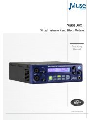
A large inductor, called the antenna coil, is<br />
connected to each antenna inside the theremin. The<br />
antenna coil, antenna capacitance, <strong>and</strong> h<strong>and</strong><br />
capacitance form a resonant circuit (Figure 1). In our<br />
design, the resonant frequencies are about 285 kHz<br />
for the pitch antenna, <strong>and</strong> about 450 kHz for the<br />
volume antenna. At or near the resonant frequency, a<br />
tiny change in h<strong>and</strong> capacitance results in a larger<br />
change in the impedance of the antenna circuit as a<br />
whole.<br />
Figure 1 - Equivalent Circuit of H<strong>and</strong> Capacitance<br />
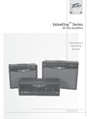
THE ETHERWAVE CIRCUIT<br />
Before looking at the schematic diagram itself, we'll<br />
review the functions of the Etherwave's circuit.<br />
Figure 2 is a block diagram showing all the circuit<br />
functions.<br />
Figure 2 - Etherwave Block Diagram<br />
UNDERSTANDING, CUSTOMIZING, AND HOT-RODDING YOUR ETHERWAVE - PAGE 2