understanding, customizing, and hot-rodding ... - Suono Elettronico
understanding, customizing, and hot-rodding ... - Suono Elettronico
understanding, customizing, and hot-rodding ... - Suono Elettronico

You also want an ePaper? Increase the reach of your titles
YUMPU automatically turns print PDFs into web optimized ePapers that Google loves.
UNDERSTANDING, CUSTOMIZING, AND<br />
HOT-RODDING<br />
YOUR ETHERWAVE ®<br />
THEREMIN<br />
UNDERSTANDING:<br />
TABLE OF CONTENTS<br />
How the Etherwave Works 1<br />
The Etherwave Circuit 2<br />
A Tour of the Schematic Diagram 3<br />
Tuning The Pitch Circuit 6<br />
Tuning the Volume Circuit 7<br />
Why is the Power Adaptor Grounded?8<br />
Can I Use Battery Power? 8<br />
CUSTOMIZING:<br />
Changing the Circuit Board 9<br />
Lowering the Output Level 9<br />
Reversing the Volume Antenna 9<br />
Pedal Control of Volume 10<br />
HOT-RODDING:<br />
The Etherwave's Auxiliary Header 10<br />
Output Amplifier for Tuner 11<br />
Output Amplifier for Headphones 11<br />
Volume CV Output 13<br />
Pitch CV <strong>and</strong> Gate Output 13<br />
INTRODUCTION<br />
We'll first explain how the Etherwave converts h<strong>and</strong><br />
movements into changes in pitch <strong>and</strong> volume of a<br />
musical tone. We hope that this explanation will<br />
help you to underst<strong>and</strong> the Etherwave's operation,<br />
<strong>and</strong> will provide the information necessary for you<br />
to add to <strong>and</strong> modify your Etherwave to meet your<br />
individual requirements.<br />
Following our explanation of the Etherwave's<br />
circuit, we'll describe several useful customizations<br />
<strong>and</strong> '<strong>hot</strong>-rod' circuit additions. They range from a<br />
simple resistor change to the construction of a<br />
complex outboard circuit. Experimenters are<br />
welcome to incorporate any or all of these into their<br />
Etherwaves. In addition, you are welcome to do<br />
your own <strong>hot</strong>-rod design, providing you have the<br />
technical background to underst<strong>and</strong> how your<br />
proposed designs will interact with the circuit of the<br />
Etherwave itself.<br />
HOW THE ETHERWAVE WORKS<br />
There are several resonant circuits, or tuned circuits,<br />
in the Etherwave theremin. Since resonant circuits<br />
are not as common or accessible in today's electronic<br />
gear as they used to be, we'll define some basic<br />
terms <strong>and</strong> concepts that will help you underst<strong>and</strong><br />
how the theremin circuit works.<br />
A resonant circuit consists of a capacitor (sometimes<br />
called a condenser) <strong>and</strong> an inductor (sometimes<br />
called a coil). A capacitor is a device consisting of<br />
two conductive plates separated by insulating<br />
material such as air or polyester. The capacitance of<br />
a capacitor depends on the size of the plates <strong>and</strong> the<br />
distance between them. An inductor is a device<br />
consisting of a coil of wire, sometimes wrapped<br />
around an iron or ferrite core. The inductance of an<br />
inductor depends on the number <strong>and</strong> size of the turns<br />
of wire <strong>and</strong> the material of the core. A resonant<br />
circuit has the property that its electrical impedance<br />
changes radically within a narrow frequency b<strong>and</strong>,<br />
the middle of which is called the resonant frequency<br />
of the circuit.<br />
HAND CAPACITANCE<br />
When you bring your h<strong>and</strong> near a theremin antenna,<br />
you are actually forming a variable capacitor in<br />
which the antenna is one 'plate' <strong>and</strong> your h<strong>and</strong> is the<br />
other. For the high frequencies <strong>and</strong> very low currents<br />
that we're talking about, your h<strong>and</strong> is effectively<br />
grounded by being attached to your body, so the<br />
antenna <strong>and</strong> your h<strong>and</strong> form a variable capacitor to<br />
ground. We call this variable capacitance h<strong>and</strong><br />
capacitance. You increase the h<strong>and</strong> capacitance by<br />
UNDERSTANDING, CUSTOMIZING, AND HOT-RODDING YOUR ETHERWAVE - PAGE 1
inging your h<strong>and</strong> nearer to the antenna. In normal<br />
theremin playing, h<strong>and</strong> capacitance is less than one<br />
picofarad, a very small capacitance change indeed!<br />
In addition to h<strong>and</strong> capacitance, a theremin antenna<br />
has a fixed capacitance to ground, which we'll call<br />
the antenna capacitance. Antenna capacitance<br />
depends mostly on the size of the antenna, <strong>and</strong> is<br />
typically 10-15 picofarads.<br />
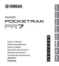
A large inductor, called the antenna coil, is<br />
connected to each antenna inside the theremin. The<br />
antenna coil, antenna capacitance, <strong>and</strong> h<strong>and</strong><br />
capacitance form a resonant circuit (Figure 1). In our<br />
design, the resonant frequencies are about 285 kHz<br />
for the pitch antenna, <strong>and</strong> about 450 kHz for the<br />
volume antenna. At or near the resonant frequency, a<br />
tiny change in h<strong>and</strong> capacitance results in a larger<br />
change in the impedance of the antenna circuit as a<br />
whole.<br />
Figure 1 - Equivalent Circuit of H<strong>and</strong> Capacitance<br />
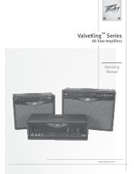
THE ETHERWAVE CIRCUIT<br />
Before looking at the schematic diagram itself, we'll<br />
review the functions of the Etherwave's circuit.<br />
Figure 2 is a block diagram showing all the circuit<br />
functions.<br />
Figure 2 - Etherwave Block Diagram<br />
UNDERSTANDING, CUSTOMIZING, AND HOT-RODDING YOUR ETHERWAVE - PAGE 2
TONE PRODUCTION AND PITCH CONTROL<br />
The Etherwave's tone is produced in a circuit<br />
configuration called a beat frequency oscillator. It<br />
consists of two high-frequency oscillators, plus a<br />
detector circuit which extracts the difference<br />
frequency, or beat frequency. One of the highfrequency<br />
oscillators (called the fixed pitch<br />
oscillator) operates at about 285 kHz, while the<br />
other high-frequency oscillator (called the variable<br />
pitch oscillator) operates over a range of about 282 -<br />
285 kHz. The difference frequency ranges from zero<br />
to about 3 kHz, which is three <strong>and</strong> a half octaves<br />
above middle C.<br />
The pitch antenna circuit is connected to the variable<br />
pitch oscillator in such a way that increases in h<strong>and</strong><br />
capacitance will decrease the variable pitch<br />
frequency as much as 3 kHz. This is how the pitch<br />
antenna circuit, in conjunction with the beat<br />
frequency oscillator circuit, enables the player to<br />
cover a usable pitch range of some five octaves (two<br />
octaves below to three octaves above middle C)<br />
simply by moving her right h<strong>and</strong> through a distance<br />
of two feet or so.<br />
VOLUME CONTROL AND<br />
TIMBRE CONTROL<br />
The volume antenna circuit consists of the volume<br />
antenna itself, in series with several inductors. It's<br />
connected to the output of the volume oscillator,<br />
which provides a high frequency signal. When the<br />
antenna circuit resonant frequency is at or near the<br />
volume oscillator frequency, a high frequency<br />
current flows through the inductors, which induces a<br />
high frequency voltage across each of the inductors.<br />
These voltages are at a maximum when the antenna<br />
circuit's resonant frequency is exactly the same as<br />
the frequency of the volume oscillator, <strong>and</strong> decrease<br />
when the antenna circuit's resonant frequency is<br />
decreased by the addition of h<strong>and</strong> capacitance to the<br />
volume antenna. The volume antenna circuit also<br />
includes a detector, which converts the high<br />
frequency voltage across one of the inductors to a<br />
direct (DC) voltage. This voltage, which is called the<br />
volume control voltage, controls the gain of a<br />
voltage-controlled amplifier (VCA). Thus, as the<br />
player brings his left h<strong>and</strong> near the volume antenna,<br />
the volume control voltage decreases, the VCA gain<br />
decreases, <strong>and</strong> the audio output signal goes from<br />
loud to complete silence. The audio output signal is<br />
line level, <strong>and</strong> may be fed to a line input of a power<br />
7amplifier or mixing console.<br />
Front panel controls include four potentiometers:<br />
two for antenna tuning <strong>and</strong> two for timbre control.<br />
The PITCH TUNING potentiometer is connected to<br />
the pitch tuning circuit, which adjusts the frequency<br />
of the fixed pitch oscillator over a small range.<br />
Similarly, the VOLUME TUNING potentiometer is<br />
connected to the volume tuning circuit, which<br />
adjusts the frequency of the volume oscillator over a<br />
small range. These circuits provide the player with a<br />
way of fine-tuning the antenna responses during<br />
performance. In earlier theremin designs these<br />
tuning functions were implemented with large<br />
variable capacitors. Such variable capacitors are no<br />
longer generally available at reasonable prices.<br />
The VCA is deliberately designed to distort the<br />
difference frequency waveform, thereby adding<br />
desirable harmonic content. The BRIGHTNESS<br />
<strong>and</strong> WAVEFORM potentiometers vary the biases on<br />
the VCA input, which change the way in which the<br />
audio waveform is distorted. The BRIGHTNESS<br />
potentiometer determines how much the waveform<br />
is distorted, <strong>and</strong> therefore the amount of the total<br />
harmonic content. The WAVEFORM potentiometer<br />
determines which harmonics will be strong, <strong>and</strong><br />
which will be weak. It is similar to a Rectangular<br />
Width control on analog synthesizers.<br />
The entire theremin circuit runs on ± 12 volts, which<br />
is supplied by a simple, small power supply. Total<br />
current consumption is about 30 milliamperes.<br />
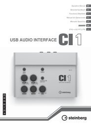
A TOUR OF THE SCHEMATIC<br />
DIAGRAM<br />
Figure 3 is the schematic diagram of the entire<br />
Etherwave circuit. Nominal DC levels (as measured<br />
with a DC voltmeter) are shown at several points in<br />
the circuit. Figure 4 shows the positions of all<br />
components on the Etherwave circuit board.<br />
The three high frequency oscillators are nearly<br />
identical, the differences being in the values of their<br />
tuned circuit elements <strong>and</strong> in the manner in which<br />
their frequencies are adjusted.<br />
Q1, Q2, <strong>and</strong> their associated circuitry comprise the<br />
variable pitch oscillator. The frequency of oscillation<br />
is determined primarily by the resonant<br />
UNDERSTANDING, CUSTOMIZING, AND HOT-RODDING YOUR ETHERWAVE - PAGE 3
UNDERSTANDING, CUSTOMIZING, AND HOT-RODDING YOUR ETHERWAVE - PAGE 4
UNDERSTANDING, CUSTOMIZING, AND HOT-RODDING YOUR ETHERWAVE - PAGE 5
frequency of L5, L12, <strong>and</strong> C1. When the variable<br />
pitch oscillator is tuned properly <strong>and</strong> the player's<br />
h<strong>and</strong> is away from the pitch antenna, the resonant<br />
frequency of the pitch antenna circuit is slightly<br />
lower than that of the variable pitch oscillator. Now,<br />
when the resonant frequency of the antenna circuit is<br />
lower than that of the oscillator circuit, the oscillator<br />
frequency is pushed higher. (The mathematics for<br />
this interaction is somewhat technical, but you can<br />
visualize it by imagining a car being pushed forward<br />
when a force is applied from the back.) In the case<br />
of a properly-tuned Etherwave, the 'loading' by the<br />
antenna circuit when the player's h<strong>and</strong> is away from<br />
the pitch antenna raises the frequency of the variable<br />
pitch oscillator by about three kHz. Then, as the<br />
player brings his h<strong>and</strong> near the pitch antenna, the<br />
difference between the resonant frequencies of the<br />
antenna circuit <strong>and</strong> the oscillator cicuit increases, the<br />
loading of the oscillator circuit by the antenna circuit<br />
decreases <strong>and</strong> the oscillator frequency falls to its<br />
'natural' (unloaded) frequency.<br />
Q3, Q4, <strong>and</strong> their associated circuitry comprise the<br />
fixed pitch oscillator, the frequency of which is<br />
determined primarily by the resonant frequency of<br />
L6, L13 <strong>and</strong> C5. Q5 <strong>and</strong> its associated cicuitry<br />
comprise the pitch tuning circuit. The circuit forms<br />
an 'active variable capacitor' which is used to make<br />
fine adjustments to the fixed pitch oscillator<br />
frequency when the instrument is being played.<br />
Front panel potentiometer P1 adjusts the current<br />
through Q5, thereby varying its active capacitance.<br />
Similarly, Q6, Q7, <strong>and</strong> their associated circuitry<br />
comprise the volume oscillator, whose frequency is<br />
determined primarily by the resonant frequency of<br />
L11, L14 <strong>and</strong> C14, plus the effect of the active<br />
variable capacitor formed by Q8 <strong>and</strong> its associated<br />
circuitry. P2 adjusts the current through Q8, thereby<br />
varying its active capacitance.<br />
C2 <strong>and</strong> C6 combine the pitch oscillator signals,<br />
while D4, R23, R24, <strong>and</strong> C23 extract the difference<br />
frequency. C2 <strong>and</strong> C6 also provide weak coupling<br />
between the two pitch oscillators, which has the<br />
effect of synchronizing the pitch oscillators when<br />
their frequencies get very close together. This has<br />
the desirable effect of providing a stable 'zero beat',<br />
so that the instrument, once properly tuned, is silent<br />
when the player steps away from it. The audio<br />
waveform at the junction of R23 <strong>and</strong> R24 is a<br />
skewed sine wave with a peak-to-peak voltage of<br />
about 0.8 volts.<br />
A detector consisting of D1, R14, <strong>and</strong> C12 is<br />
connected across L7 of the volume antenna circuit.<br />
When the resonant frequency of the antenna circuit<br />
is equal to the volume oscillator frequency, the DC<br />
component of the voltage at the junction of C12 <strong>and</strong><br />
R14 is about -3 volts <strong>and</strong> decreases as the player<br />
brings his left h<strong>and</strong> near the volume antenna. This<br />
voltage is converted into a current, which is then<br />
used to control the gain of the instrument's VCA.<br />
U3 is a 'dual operational transconductance amplifier'.<br />
Either section may be used as a VCA or a<br />
programmable op-amp. Section B is used to convert<br />
the volume control voltage to a current, which is<br />
then used to control the gain of Section A. The audio<br />
waveform is applied to the input of Section A, at a<br />
level which is high enough to clip it. This has the<br />
effect of reshaping the audio waveform from a<br />
skewed sine to a quasi-rectangular wave, which is<br />
very similar to the waveform of Theremin's original<br />
instruments. P3 varies the input resistance of Section<br />
A, which determines the amount that the audio<br />
waveform is clipped. P4 shifts the bias at the input<br />
of U3-A, which changes the waveform width <strong>and</strong><br />
therefore the sound's timbre. C24 <strong>and</strong> C26 roll off<br />
the high frequency harmonics to give a pleasant<br />
cello-like tonal balance. The maximum level at the<br />
audio output jack is about 0 dBm (0.8V rms).<br />
The ± 12V power supply consists of an external<br />
power adaptor which delivers 14 volts AC at 200<br />
milliamperes to two half-wave rectifiers D2 <strong>and</strong> D3,<br />
<strong>and</strong> two voltage regulators U1 <strong>and</strong> U2.<br />
TUNING THE PITCH CIRCUIT<br />
The circuit board of your Etherwave theremin has<br />
been assembled, tested, <strong>and</strong> adjusted at the factory.<br />
However, you may find it desirable or necessary to<br />
trim the adjustments of L5, L6, or L11. For instance,<br />
you may want to set your Etherwave to cover a<br />
slightly different pitch range, or the finish you used<br />
for your cabinet might have slightly different<br />
electrical properties than that which we adjust the<br />
boards for at the factory.<br />
Before tuning, clean off your workbench <strong>and</strong> move<br />
aside large conductive objects like desk lamps <strong>and</strong><br />
test gear. Leave a clear space of two or three feet<br />
around your work area. Place the cabinet base in the<br />
middle of the cleared space, <strong>and</strong> put the pitch<br />
antenna in place.<br />
Using a clip lead or a temporarily-soldered wire<br />
jumper, connect the two leads of C28 together. (C28<br />
is a small capacitor, about 3" to the left of the<br />
PITCH ANTENNA connection on the Etherwave<br />
circuit board.) Then connect the instrument's audio<br />
UNDERSTANDING, CUSTOMIZING, AND HOT-RODDING YOUR ETHERWAVE - PAGE 6
output to headphones or a monitor amplifier. Now<br />
follow these steps to adjust L5 <strong>and</strong> L6:<br />
1. Set P1 (the Pitch Tuning control) to its midposition.<br />
2. Grasp <strong>and</strong> hold the pitch antenna with one h<strong>and</strong>.<br />
With the other h<strong>and</strong>, adjust L6 for zero beat.<br />
(Note: If the slug in L5 is fully<br />
counterclockwise, you have to turn it clockwise<br />
a turn or so in order to hear zero beat.) Then<br />
carefully turn L6 counterclockwise until you<br />
hear a pitch of about 3 kHz (3-1/2 octaves above<br />
middle C).<br />
3. Let go of the pitch antenna. Slowly retract your<br />
h<strong>and</strong> from the vicinity of the antenna. You will<br />
hear the pitch go down.<br />
• If the pitch does not go down to zero beat when<br />
you've retracted your h<strong>and</strong> completely <strong>and</strong><br />
stepped back, then L5 is set to too low an<br />
inductance. Advance the slug in L5 (that is, turn<br />
it clockwise) a small amount,- perhaps 1/10 turn<br />
or so,- <strong>and</strong> repeat steps 2 <strong>and</strong> 3.<br />
• If the pitch goes to zero beat <strong>and</strong> then begins to<br />
ascend as you retract your h<strong>and</strong>, then L5 is set to<br />
too high an inductance. Turn the slug in L5<br />
counterclockwise a small amount, <strong>and</strong> repeat<br />
steps 2 <strong>and</strong> 3.<br />
• If the pitch jumps abruptly to a very different<br />
pitch as you retract your h<strong>and</strong>, then L5 is set to<br />
far too high an inductance. Turn the slug in L5<br />
counterclockwise perhaps 1/4 turn, <strong>and</strong> repeat<br />
steps 2 <strong>and</strong> 3.<br />
Eventually you will converge on the proper settings<br />
of L5 <strong>and</strong> L6. The idea is to achieve settings in<br />
which the pitch is at zero beat when you've stepped<br />
away from the theremin, begins to ascend when your<br />
body is about 24" from the pitch antenna, <strong>and</strong> is<br />
about 3 kHz when your h<strong>and</strong> touches the pitch<br />
antenna. Tap lightly on L5 <strong>and</strong> L6 as you converge<br />
on the proper settings, as this will stabilize the<br />
tuning slug positions.<br />
This completes the tuning of the Pitch Oscillators. In<br />
performance, the exact pitch tuning is achieved by<br />
adjusting the Pitch Tuning control.<br />
TUNING THE PITCH CIRCUIT<br />
FOR DIFFERENT PITCH RANGES<br />
With L5 <strong>and</strong> L6 set as described above, your<br />
Etherwave will cover a musical pitch range of five<br />
octaves - two octaves below middle C to three<br />
octaves above middle C. (Of course, it will produce<br />
tones below two octaves below middle C, but this<br />
part of the pitch range is not particularly useful for<br />
theremin playing.) You can retune the Etherwave's<br />
pitch section to cover a smaller or a larger pitch<br />
range. By covering a range up to two octaves above<br />
middle C for instance, your instrument's range will<br />
be only four octaves, but the intervals will be spaced<br />
farther apart <strong>and</strong> it will be easier for you to play a<br />
desired interval. Similarly, by covering a range of up<br />
to four octaves above middle C, your instrument will<br />
cover a six-octave range, but the intervals will be<br />
spaced very close together <strong>and</strong> proper interval<br />
production will be proportionally more difficult.<br />
To retune your Etherwave for a four-octave range,<br />
first reposition the heavy wire going to the pitch<br />
antenna connector, so that it is close to the aluminum<br />
foil. (This will lower the resonant frequency of the<br />
antenna circuit.) Then repeat the tuning procedure<br />
given earlier, substituting 1.5 kHz (2-1/2 octaves<br />
above middle C) for 3 kHz in Step 2.<br />
Similarly, to retune your Etherwave for a six-octave<br />
range, raise the heavy wire going to the pitch<br />
antenna connector as high as possible. Then repeat<br />
the tuning procedure, substituting 5 kHz (slightly<br />
higher than four octaves above middle C) for 3 kHz<br />
in Step 2.<br />
TUNING THE VOLUME CIRCUIT<br />
A. Using a Voltmeter: Remove the temporary<br />
shorting connection across C28. Connect a voltmeter<br />
from pin 12 of U3 to ground <strong>and</strong> install the volume<br />
antenna. Position your Etherwave so that the volume<br />
antenna is at least a foot from table tops, furniture,<br />
etc. Follow these steps to adjust L11:<br />
1. Set the VOLUME knob to its mid position.<br />
2. Carefully turn the slug in L11 counterclockwise<br />
until it is out as far as it will go. The meter<br />
should read about -12 volts.<br />
3. Slowly turn the slug clockwise. At some point<br />
you will see the voltage begin to rise from -12<br />
volts. Stop when the voltage goes through zero<br />
<strong>and</strong> becomes positive. You should then notice<br />
that bringing your h<strong>and</strong> near the volume<br />
UNDERSTANDING, CUSTOMIZING, AND HOT-RODDING YOUR ETHERWAVE - PAGE 7
antenna lowers the voltage; the meter should<br />
read about minus 12 volts when your h<strong>and</strong> is<br />
two or three inches from the volume antenna.<br />
This completes the tuning of the Volume Oscillator.<br />
In performance, the exact volume tuning is achieved<br />
by adjusting the Volume Tuning control.<br />
B. Adjusting L11 without a voltmeter: Remove<br />
the temporary shorting connection across C28.<br />
Install the volume antenna. Position your Etherwave<br />
so that the volume antenna is at least a foot from<br />
furniture <strong>and</strong> other large objects. Follow these steps<br />
to adjust L11:<br />
1. Set the VOLUME knob to its mid position.<br />
2. Carefully turn the slug in L11 counterclockwise<br />
until it is out as far as it will go. Then turn on<br />
your amplifier <strong>and</strong> set its volume control so that<br />
the theremin tone will be audible but soft.<br />
3. Slowly turn the slug clockwise. At some point<br />
you will hear the theremin tone. As you turn the<br />
slug in L11, the tone will get louder, reach a<br />
maximum loudness, <strong>and</strong> then get softer. Turn the<br />
slug back to the maximum loudness, <strong>and</strong> notice<br />
how loud the tone is.<br />
4. Slowly turn the slug counterclockwise until the<br />
tone is about half its maximum loudness. You<br />
should then notice that bringing your h<strong>and</strong> near<br />
the volume antenna lowers the volume, <strong>and</strong> the<br />
tone is complete silent when your h<strong>and</strong> is two or<br />
three inches from the volume antenna.<br />
This completes the tuning of the Volume Oscillator.<br />
In performance, the exact volume tuning is achieved<br />
by adjusting the Volume Tuning control.<br />
WHY IS THE POWER ADAPTOR<br />
GROUNDED?<br />
In order for any h<strong>and</strong>-capacitance device to work<br />
properly, there has to be a good path for high<br />
frequency currents to flow to ground. Older vacuum<br />
tube theremins used large power transformers, <strong>and</strong><br />
these provided high frequency ground paths because<br />
of the large capacitances between windings.<br />
Transistor theremins use much less power than their<br />
vacuum-tube ancestors, <strong>and</strong> their power transformers<br />
are therefore much smaller. Under certain<br />
conditions, a supplementary ground path is needed<br />
for stable operation <strong>and</strong> good tone color. For this<br />
reason, the power adaptor that is supplied with your<br />
Etherwave provides a direct connection to ground.<br />
That is the purpose of the third prong on the power<br />
adaptor.<br />
If you are using your Etherwave with an amplifier<br />
that also has a direct connection to ground (i.e. a<br />
three-prong power plug), you may experience a<br />
small amount of hum from the ground loop,-<br />
especially if your amplifier is plugged in to a<br />
different power circuit than your Etherwave. If this<br />
happens, simply use a 'ground-lifter' 3-prong-to-2-<br />
prong adaptor on your Etherwave power adaptor.<br />
CAN I USE BATTERY POWER?<br />
Your Etherwave must be grounded somehow. If you<br />
want to battery-power your Etherwave while it is<br />
connected to headphones, or to an ungrounded<br />
battery-powered amplifier, you must provide a<br />
connection to ground or to some sort of a large<br />
metallic structure like a steel building frame or<br />
plumbing system.<br />
If you use batteries, you must supply between 15<br />
<strong>and</strong> 25 volts to each of the Etherwave's power<br />
regulators. Apply the positive voltage to the (+) side<br />
of C19 on the Etherwave circuit board, the negative<br />
voltage to the (-) side of C20, <strong>and</strong> the common to<br />
ground. A double-pole switch may be used to turn<br />
on the batteries. Figure 5 shows how to hook four 9-<br />
volt batteries to power your Etherwave in the<br />
absence of regular AC power. Keep in mind that the<br />
Etherwave draws about 30 milliamperes, so a set of<br />
four regular 9-volt batteries will last for only a few<br />
hours.<br />
Figure 5 - Battery power circuit for the Etherwave<br />
UNDERSTANDING, CUSTOMIZING, AND HOT-RODDING YOUR ETHERWAVE - PAGE 8
CUSTOMIZING YOUR ETHERWAVE<br />
Here are two simple changes to the Etherwave that<br />
you can implement simply by changing a few<br />
components on the Etherwave circuit board. If<br />
you're not familiar with removing <strong>and</strong> replacing<br />
components on circuit boards, then follow these<br />
steps carefully:<br />
1. Using a diagonal cutting pliers, cut away as<br />
much of the component to be removed as<br />
possible.<br />
2. Using a soldering iron, heat one of the circuit<br />
board pads from which the unwanted component<br />
was just cut, until the solder is molten. Then,<br />
while the solder is still molten, tap the circuit<br />
board on a hard surface to knock out the molten<br />
solder <strong>and</strong> the short stub of wire from the<br />
removed component. Alternately, you may use a<br />
'solder-sucker' tool or 'solder-wick' to remove<br />
the molten solder. The purpose of this step is to<br />
remove the stub of component wire <strong>and</strong> all the<br />
solder from the hole in the pad. Do not overheat<br />
the pad. Before proceeding past this step, inspect<br />
carefully for solder splashes on the circuit board.<br />
3. Repeat the above step on the other pad(s) from<br />
which the unwanted component was cut away.<br />
4. Bend the wires of the new component so that it<br />
slips into the desired location. Then solder the<br />
new component in place <strong>and</strong> cut off the excess<br />
wire.<br />
LOWERING THE LEVEL OF THE<br />
ETHERWAVE'S AUDIO OUTPUT SO<br />
IT WILL WORK WITH A<br />
GUITAR OR BASS AMPLIFIER<br />
The Etherwave's maximum audio output is normally<br />
0.5 volts to 1.0 volts RMS. This is what is<br />
commonly known as 'line level', <strong>and</strong> is the correct<br />
voltage level for keyboard amplifiers, line level<br />
inputs of mixing consoles, <strong>and</strong> 'aux' inputs of home<br />
stereo amplifiers. However, it is often too high for<br />
guitar <strong>and</strong> bass amplifier inputs, which are designed<br />
for signals that are much weaker.<br />
remove R33 (4.7K resistor) <strong>and</strong> replace it with a<br />
47K resistor. Figure 4 shows the location of R33.<br />
REVERSING THE RESPONSE<br />
DIRECTION OF THE ETHERWAVE'S<br />
VOLUME ANTENNA<br />
Authentic theremins are designed so that the volume<br />
is loudest when the player's left h<strong>and</strong> is away from<br />
the volume antenna, <strong>and</strong> silent when the player's left<br />
h<strong>and</strong> is close to the volume antenna. This enables the<br />
player to articulate individual notes with quick, short<br />
movements of the left h<strong>and</strong> toward the volume<br />
antenna, <strong>and</strong> to use large, graceful movements to<br />
impart expressive dynamics.<br />
In certain applications, it may be desirable for the<br />
volume antenna to operate so that the instrument is<br />
silent when the player's left h<strong>and</strong> is away from the<br />
volume antenna, <strong>and</strong> loudest when the player's left<br />
h<strong>and</strong> is close to the volume antenna. An example is a<br />
demonstration setup in which the instrument is silent<br />
when people are walking around it, <strong>and</strong> becomes<br />
audible only when a player brings his left h<strong>and</strong><br />
within a few inches of the volume antenna.<br />
Follow these instructions to reverse the response<br />
direction of the Etherwave's volume antenna:<br />
1. Remove Diode D5.<br />
2. Remove the LM13600 chip from its socket,<br />
bend pins 13 <strong>and</strong> 14 up so they will not make<br />
contact with the socket, <strong>and</strong> reinstall the chip in<br />
its socket.<br />
3. Solder a short piece of insulated wire from pin<br />
13 to the left side of C27.<br />
4. Solder a short piece of insulated wire from pin<br />
14 to the left side of R35.<br />
5. Retune L11 for desired volume antenna<br />
response.<br />
Figure 6 shows what the Etherwave board should<br />
look like after the modification.<br />
To reduce the Etherwave's audio output level so that<br />
it will not overload the input of a guitar amplifier,<br />
UNDERSTANDING, CUSTOMIZING, AND HOT-RODDING YOUR ETHERWAVE - PAGE 9
Figure 6 - Reversing the Etherwave's volume antenna<br />
USING A PEDAL TO CONTROL<br />
VOLUME<br />
Under some special conditions, you may find it<br />
desirable to control your Etherwave's volume from a<br />
pedal or an external potentiometer, rather than with<br />
the instrument's volume antenna. For instance, you<br />
may wish to play a keyboard with your left h<strong>and</strong><br />
while playing the Etherwave's pitch with your right<br />
h<strong>and</strong>.<br />
The most straightforward way of using a pedal for<br />
the Etherwave's volume control is to connect the<br />
VCA OUT voltage to +12V, thereby setting the<br />
Etherwave's audio output to maximum level, <strong>and</strong><br />
then feeding the audio output through a conventional<br />
volume control pedal. To connect the VCA OUT<br />
voltage to to +12V, carefully solder a short wire<br />
from pad #2 to pad #6 of the auxiliary header. (See<br />
the description of the Auxiliary Header which<br />
follows.)<br />
HOT-RODDING YOUR ETHERWAVE<br />
The Etherwave circuit board has pads for an<br />
auxiliary header with 0.1" pin spacing. Looking<br />
down on the board from the front of the instrument,<br />
you will see the pads along the upper edge. These<br />
pads provide power <strong>and</strong> signals for use by external<br />
custom circuitry. You will find it convenient to<br />
connect to these pads by soldering a header (for<br />
instance Molex 22-03-2081) in the pads, <strong>and</strong><br />
equipping your external circuitry with a mating<br />
connector.<br />
There are six pads on circuit boards built before<br />
July, 1996, <strong>and</strong> eight pads on boards built starting<br />
July, 1996. Starting from the left, the pads are:<br />
PAD NUMBER<br />
FUNCTION<br />
1 GROUND<br />
2 VCA OUT<br />
3 AMP IN (incorrectly marked 'AMP<br />
OUT' on earlier boards)<br />
4 AMP OUT (incorrectly marked<br />
'AMP IN' on earlier boards)<br />
5 -12 V ( -12 volts, 25 milliamperes<br />
maximum)<br />
6 +12 V ( +12 volts, 25 milliamperes<br />
maximum)<br />
7 AUDIO (signal across R24, only on<br />
later boards)<br />
8 AUX (for use by experimenter, only<br />
on later boards)<br />
The VCA OUT pad goes from -12V (silence) to<br />
+12V (loudest tone) as you vary the position of<br />
your h<strong>and</strong> near the volume antenna. It is an<br />
unbuffered, high impedance point, so if you want to<br />
use this signal, you should not load it with an<br />
impedance of less than 100K.<br />
The AMP IN <strong>and</strong> AMP OUT pads are the base <strong>and</strong><br />
emitter, respectively, of a transistor (actually two<br />
transistors connected in a 'Darlington' configuration)<br />
that is part of U3. The collector of the transistor is<br />
permanently connected to +12V. You can use this<br />
transistor as an emitter follower to buffer either the<br />
VCA OUT or selected other points in the Etherwave<br />
circuit. The VOLUME CONTROL VOLTAGE<br />
OUTPUT circuit, described later, is an example of<br />
how to use the transistor which is connected to AMP<br />
IN <strong>and</strong> AMP OUT.<br />
The +12V <strong>and</strong> -12V pads may be used to supply up<br />
to 25 milliamperes for powering external circuits.<br />
UNDERSTANDING, CUSTOMIZING, AND HOT-RODDING YOUR ETHERWAVE - PAGE 10
Two additional pads are provided on circuit boards<br />
built after July 1, 1996. They are AUDIO <strong>and</strong> AUX.<br />
AUDIO provides the same signal that feeds the<br />
Etherwave's voltage-controlled amplifier. It's useful<br />
for amplifying <strong>and</strong> processing the Etherwave's tone<br />
before it is shaped by the VCA. The AUX pad is<br />
connected only to another pad on the Etherwave<br />
board, <strong>and</strong> is useful for providing a connection of<br />
your choice through the auxiliary header.<br />
OUTPUT AMPLIFIER FOR TUNER<br />
The addition of an audio output for an electronic<br />
tuner will enable you to see exactly what pitch<br />
you're about to play, even before you take your h<strong>and</strong><br />
away from the volume antenna to start the tone.<br />
In Figure 7, R23, R24, D4 <strong>and</strong> C23 are components<br />
on the Etherwave board. The audio signal across<br />
R24 is a constant 600 millivolts peak-to-peak. This<br />
signal overdrives the LM3080, producing a clean,<br />
rounded rectangular wave of about 1.4 volts peak-topeak.<br />
The output appears at pin 6 of the LM3080. It<br />
may be connected directly to the tuner input, or to a<br />
small jack into which the tuner may be plugged. The<br />
jack may be mounted on the front panel. You will<br />
need to carefully drill a 1/4" hole for it, positioning<br />
it so it does not get in the way of existing panel<br />
components<br />
The LM3080 amplifier circuit may be built on a<br />
small piece of prototyping circuit board material,<br />
<strong>and</strong> then mounted inside the Etherwave cabinet. All<br />
connections to the Etherwave circuitry are made<br />
through the Etherwave's auxiliary header, which you<br />
must install yourself on the Etherwave board. The<br />
one exception to this is the connection to the<br />
junction of R23 <strong>and</strong> R24 on earlier boards, which<br />
does not go through the header <strong>and</strong> which you must<br />
solder directly to R24. (See Figure 7.)<br />
Parts list for Output Amplifier for Tuner:<br />
C1 1nF 50V 10% ceramic capacitor<br />
R1 10 kΩ 1/4 watt 5% resistor<br />
R2 47 kΩ 1/4 watt 5% resistor<br />
R3 1 kΩ 1/4 watt 5% resistor<br />
R4 220 kΩ 1/4 watt 5% resistor<br />
U1 LM3080N or CA3080E integrated circuit<br />
6 or 8-Pin PCB-mount header<br />
(Molex # 22-23-2061 or 22-23-2081)<br />
Prototyping board<br />
(Radio Shack # 276-1396 or 276-147A)<br />
Miniature panel-mount phone jack<br />
(Radio Shack # 274-251A)<br />
OUTPUT AMPLIFIER FOR<br />
HEADPHONES<br />
The regular audio output of the Etherwave is less<br />
than 2 volts peak-to-peak, with an output impedance<br />
of about 2.4 Kilohms. This is a good level <strong>and</strong><br />
impedance for feeding into a line-level input of an<br />
amplifier, recorder, <strong>and</strong> mixing console, but is too<br />
weak for most headphones.<br />
The circuit in Figure 8 boosts the Etherwave output<br />
so you can practice with headphones. The regular<br />
audio output of the Etherwave is boosted by about<br />
20 dB. The amplifier's output is delivered to the<br />
headphones through 330 ohm resistors, which<br />
protect both the headphones <strong>and</strong> the TL081<br />
amplifier from unexpected electrical 'surprises'.<br />
(Note: Increase the values of the protecting resistors<br />
to 1,000 ohms if the sound level in your headphones<br />
is uncomfortably loud.)<br />
The headphone amplifier may be built on a small<br />
piece of prototyping circuit board material, mounted<br />
inside the Etherwave cabinet, <strong>and</strong> connected to the<br />
Etherwave circuit board through its auxiliary header.<br />
If your Etherwave circuit board is an earlier version,<br />
you will also need to solder a wire directly between<br />
the junction of R33 <strong>and</strong> R34 on the Etherwave<br />
board, <strong>and</strong> the input of your headphone amplifier<br />
circuit. If your Etherwave circuit board is a later<br />
version, you will need to solder a wire from the<br />
junction of R33 <strong>and</strong> R34, to the 'Aux' pad near the<br />
auxiliary header. You may then connect pin #8 of<br />
the auxiliary header to the input of your headphone<br />
amplifier.<br />
The headphones jack may be mounted on the front<br />
panel. You will need to carefully drill a 1/4" hole for<br />
it, positioning it so it does not get in the way of<br />
existing panel components.<br />
Parts List for Output Amplifier For Headphones<br />
C1 100pF 50V 10% ceramic capacitor<br />
R1 10 kΩ 1/4 watt, 5% resistor<br />
R2 100 kΩ 1/4 watt, 5% resistor<br />
R3, R4 330 Ω 1/4 watt, 5% resistor<br />
U1 TL081 Operational Amplifier<br />
1/8” Miniature stereo phone jack<br />
(Radio Shack # 274-249A)<br />
6 or 8-Pin PCB-mount header (Molex # 22-23-2061 or<br />
22-23-2081)<br />
Prototyping board (Radio Shack # 276-1396 or 276-<br />
147A)<br />
UNDERSTANDING, CUSTOMIZING, AND HOT-RODDING YOUR ETHERWAVE - PAGE 11
UNDERSTANDING, CUSTOMIZING, AND HOT-RODDING YOUR ETHERWAVE - PAGE 12
VOLUME CONTROL VOLTAGE (CV)<br />
OUTPUT CIRCUIT<br />
With additional circuitry consisting of four resistors<br />
<strong>and</strong> one capacitor, you can produce a buffered<br />
control voltage that goes from +10V to zero as you<br />
bring your left h<strong>and</strong> near the Etherwave's volume<br />
antenna. You can then use this voltage as a control<br />
input to a modular analog synthesizer or similar<br />
voltage-controlled device.<br />
Figure 9a shows the existing VCA chip on the<br />
Etherwave board, as well as the outboard circuitry<br />
that must be added. When the Etherwave is<br />
operating normally, the voltage at pin 12 of U3 goes<br />
from a maximum of +11 volts to a minimum of -11<br />
volts as you approach the volume antenna with your<br />
left h<strong>and</strong>. This circuit point is high impedance, <strong>and</strong><br />
is not capable of controlling outboard circuitry<br />
directly. However, there is an unused buffer<br />
transistor within U3. This transistor, plus a high<br />
impedance voltage divider consisting of outboard<br />
resistors R2 <strong>and</strong> R3, convert the high impedance<br />
voltage at pin 12 (over the range +11V to -11V) to a<br />
low impedance buffered voltage at pin 9 (over the<br />
range +10 volts to zero). R1 provides operating<br />
current to the transistor, R4 is a protective resistor,<br />
<strong>and</strong> C1 suppresses noise <strong>and</strong> hum.<br />
R1-4 <strong>and</strong> C1 can be placed on a very small piece of<br />
prototyping board, which can then be wired in-line<br />
between the connections to the auxiliary header <strong>and</strong><br />
the CV output jack. The jack may be mounted on or<br />
under the floor of the Etherwave's cabinet base.<br />
Figure 9b shows how the parts can be arranged on<br />
the prototyping board.<br />
C1<br />
R1<br />
R2<br />
R3<br />
R4<br />
10 nF 50V 10% ceramic capacitor<br />
10 kΩ 1/4 watt 5% resistor<br />
1.0 MΩ 1/4 watt 5% resistor<br />
1.1 MΩ 1/4 watt 5% resistor<br />
1 kΩ 1/4 watt 5% resistor<br />
6 or 8-Pin PCB-mount header (Molex # 22-03-2061<br />
or 22-23-2081)<br />
Prototyping board (Radio Shack # 276-1396 or<br />
276-147A)<br />
Miniature panel-mount phone jack (Radio Shack<br />
# 274-251A)<br />
Figure 9b - Component Layout of Volume CV Board<br />
PITCH CONTROL VOLTAGE<br />
AND GATE OUTPUT CIRCUIT<br />
We'll now describe a high accuracy pitch-to-voltage<br />
converter circuit which you can build <strong>and</strong> then use to<br />
control the pitch of a wide variety of analog<br />
synthesis equipment from your Etherwave. In order<br />
to do this, the circuit must produce a control voltage<br />
which increases precisely one volt for every octave<br />
increase of the Etherwave's pitch. Our circuit<br />
performs this function over the Etherwave's entire<br />
pitch range with high accuracy, speed, <strong>and</strong> stability.<br />
It is somewhat more complex than the other circuits<br />
described in this manual. However, all parts except<br />
for one are inexpensive <strong>and</strong> readily-available. The<br />
one special component, a temperature-compensating<br />
resistor, is available from Big Briar. If you're an<br />
experienced 'hardware hacker', you will be able to<br />
build <strong>and</strong> test this circuit.<br />
Figure 10 shows the circuit's schematic, while Figure<br />
11, shows waveforms at various points in the circuit.<br />
Refer to these figures while reading the circuit<br />
description which follows.<br />
UNDERSTANDING, CUSTOMIZING, AND HOT-RODDING YOUR ETHERWAVE - PAGE 13
UNDERSTANDING, CUSTOMIZING, AND HOT-RODDING YOUR ETHERWAVE - PAGE 14
The SAMPLE AND HOLD section transfers the<br />
period voltage across C5 during time slot Q2, to C6.<br />
C6 then holds the period voltage until the next Q2<br />
time slot. Thus, the period voltage at the output of<br />
U4:B is updated every two cycles of the Etherwave's<br />
audio.<br />
The PERIOD-TO-PITCH section takes advantage of<br />
the following property of a pair of junction<br />
transistors: the ratio of the collector currents flowing<br />
through the transistors is proportional to the<br />
exponential of the voltage difference between the<br />
two transistor bases. Without going into<br />
mathematical detail, we can say that, because the<br />
numerical relationship between period <strong>and</strong> pitch is<br />
exponential, this circuit computes the one-volt-peroctave<br />
pitch voltage from the period voltage input.<br />
The AUDIO CYCLE TIMING section divides two<br />
complete cycles of the Etherwave's audio into four<br />
time slots. The audio waveform from the<br />
Etherwave's detector is amplified by U1:A. The<br />
amplified waveform at pin 5 of U1 is about 20 volts<br />
peak-to-peak, <strong>and</strong> is somewhat clipped. U2:A <strong>and</strong><br />
U2:B are connected as inverting Schmitt triggers.<br />
They convert the audio waveform into square waves<br />
of opposite polarities. C3-R6 <strong>and</strong> C4-R7 are<br />
differentiating networks whose outputs are skinny<br />
pulses. The output of U2:C is a series of squared-off<br />
skinny pulses, occurring at the rate of two per audio<br />
cycle. These advance the counter so that counter<br />
outputs Q0 - Q3 go on in a sequence that repeats<br />
every two cycles of audio.<br />
The PERIOD VOLTAGE section produces a<br />
voltage, called the period voltage, that is<br />
proportional to the length of a single cycle of the<br />
Etherwave's audio. U1:B <strong>and</strong> its associated circuitry<br />
is a constant-current source which is turned on by<br />
counter outputs Q0 <strong>and</strong> Q1. The current charges C5.<br />
At the end of the Q1 time slot, C5 has been charging<br />
for exactly one period of the audio waveform. U4:A<br />
is a unity gain buffer, the output of which follows<br />
the voltage across C5. Switches U5:A <strong>and</strong> U5:C,<br />
which are turned on during the Q3 time slot,<br />
discharge C5 so there is no voltage across it when<br />
the next Q0 time slot begins.<br />
The GATE section produces a +10V gate output<br />
whenever a) the Etherwave audio frequency is more<br />
than 20 Hz or so, <strong>and</strong> b) the Volume CV is greater<br />
than 1/2 volt. This signal can be used to turn on<br />
envelope generators <strong>and</strong> synchronize modulating<br />
waveforms in analog synthesis equipment.<br />
CONSTRUCTION HINTS<br />
This entire circuit, as well as the PITCH, VOLUME,<br />
<strong>and</strong> GATE output jacks, may be built into a small<br />
untility box that can then be mounted on the<br />
microphone st<strong>and</strong>, immediately under the<br />
Etherwave. A neat connection between the<br />
Etherwave auxiliary header <strong>and</strong> this CV output<br />
circuit may be made with a short length of 8-<br />
conductor ribbon cable. You may want to cut a<br />
clearance slot on the edge of the Etherwave base to<br />
allow room for the ribbon cable to feed through the<br />
cabinet base without being pinched.<br />
Except for R16, all electronic components are<br />
st<strong>and</strong>ard <strong>and</strong> are readily available from most parts<br />
distributors. R16 is a positive-temperaturecoefficient<br />
resistor that compensates for normal<br />
temperature variations within Q4 <strong>and</strong> Q5. It should<br />
be mounted very near U7. Also, it is a delicate<br />
component because it is wound from extremely fine<br />
resistance wire. H<strong>and</strong>le it gently <strong>and</strong> take care not to<br />
bend the leads close to the body of the component.<br />
They're available from Big Briar. Price, including<br />
shipping, is $10.<br />
The SCALE <strong>and</strong> RANGE adjustments should be<br />
high-quality cermet trimmers.<br />
SETTING THE ADJUSTMENTS<br />
UNDERSTANDING, CUSTOMIZING, AND HOT-RODDING YOUR ETHERWAVE - PAGE 15
When your Pitch CV circuit is working properly, the<br />
Pitch CV Output voltage should be zero volts when<br />
the Etherwave is producing a pitch one octave below<br />
middle C (130.8 Hz.), <strong>and</strong> should go up by exactly<br />
one volt for every one-octave increase in pitch. The<br />
SCALE adjustment sets the pitch voltage difference<br />
that you get when you increase pitch by one octave,<br />
while the RANGE adjustment sets the voltage that<br />
you get when you produce one octave below middle<br />
C.<br />
The SCALE <strong>and</strong> RANGE adjustments are most<br />
easily set by feeding an audio test oscillator signal to<br />
the Audio In connection, in place of the Etherwave<br />
audio output. You should measure the test<br />
oscillator's frequency with a frequency counter, <strong>and</strong><br />
measure the Pitch CV Output voltage with an<br />
accurate digital voltmeter.<br />
After connecting the test equipment to your circuit<br />
as described above, connect the Etherwave <strong>and</strong><br />
apply ±12V power by turning the Etherwave on. If<br />
you have an oscilloscope, verify that the waveforms<br />
shown in Figure 10 are present. If they are, then<br />
proceed as follows:<br />
1. Set the test oscillator at 130 Hz. Note the voltage<br />
at the Pitch CV Output. Set the RANGE<br />
adjustment so the Pitch CV Output is exactly<br />
zero volts.<br />
2. Set the test oscillator to 2080 Hz. Set the<br />
SCALE adjustment so that the Pitch CV output<br />
is exactly +4.00 volts.<br />
3. Repeat steps 1. <strong>and</strong> 2. until no further<br />
adjustment is needed.<br />
Parts list for Pitch CV <strong>and</strong> Gate Circuit<br />
Note: Unless otherwise indicated, capacitors are 50V,<br />
10% ceramic, <strong>and</strong> resistors are 1/4W 5%.<br />
C1<br />
220nF<br />
C2, C3, C4 1nF<br />
C5, C6 100nF 50V 10% Polypropylene Capacitor<br />
C7, 100pF<br />
C8<br />
330pF<br />
C9, C10 10nF<br />
D1, D2 1N4148 or 1N914B Diode<br />
P1 10 k multiturn cermet trimmer<br />
(Bournes 3299Y-103)<br />
P2 50 k multiturn cermet trimmer<br />
(Bournes 3299Y-503)<br />
Q1 2N3906 PNP transistor<br />
Q2, Q3 2N3904 NPN transistor<br />
R1, R2, R15, R18 47 kΩ<br />
R3, R4, R5, R12, R13 22 kΩ<br />
R6, R7, R20, R21, R25 10 kΩ<br />
R8, R9 680 kΩ<br />
R10, R11, R19 330Ω<br />
R16<br />
1 kΩ positive temp. coeff. resistor<br />
R14<br />
1.2 MΩ<br />
R17<br />
220 kΩ<br />
R28, R31 470 kΩ<br />
R22, R23, R27 10 MΩ<br />
R24<br />
2.2 kΩ<br />
R26<br />
100 kΩ<br />
R29, R30 1 MΩ<br />
U1 LM13600N dual operational transconductance<br />
amplifier (National Semiconductor)<br />
U2, U8 CD4093E Quad 2-input NAND Schmitt trigger<br />
U3 CD4022E Divide-by-eight Johnson counter<br />
U4, U6 TL062 Operational amplifier<br />
U5 4016 Quad bilateral switch<br />
U7 LM 3046 or LM3086 Transistor Array<br />
6 or 8-Pin PCB-mount header<br />
(Molex # 22-23-2061 or 22-23-2081)<br />
Prototyping board<br />
(Radio Shack # 276-1396 or 276-147A)<br />
Miniature panel-mount phone jacks<br />
(Radio Shack # 274-251A)<br />
ENTIRE CONTENTS © 2003 Moog Music Inc.<br />
Moog Music Inc.<br />
554C RIVERSIDE DRIVE<br />
ASHEVILLE, NC 28801<br />
PHONES (800) 948-1990 <strong>and</strong> (828) 251-0090<br />
email: info@moogmusic.com<br />
UNDERSTANDING, CUSTOMIZING, AND HOT-RODDING YOUR ETHERWAVE - PAGE 16