Customizing Accessories ( Excerpt)
Customizing Accessories ( Excerpt)
Customizing Accessories ( Excerpt)

Create successful ePaper yourself
Turn your PDF publications into a flip-book with our unique Google optimized e-Paper software.
<strong>Customizing</strong> <strong>Accessories</strong><br />
<strong>Customizing</strong> <strong>Accessories</strong> ( <strong>Excerpt</strong>)<br />
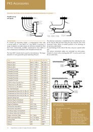
To enable your own customizing of INGU N Fixtures we supply the<br />
matching accessories. In the following is a choice of components<br />
from our extensive <strong>Accessories</strong> catalog. Ask for this catalog as well<br />
as our Test Probes and RF-Probes catalogs. Alternatively you can<br />
download the catalogs from our homepage.<br />
Marking Units<br />
The INGU N Marking Units excel themselves with their sturdiness,<br />
compact size, simple assembly and their long-life. We offer vari -<br />
ous types to support all Fixture designs and concepts.<br />
Electrical Marking Units for „Good Marking“<br />
Part No. 24447 Marking Unit with scratching Engraver<br />
Ø 12 x 60 mm (SW 14 mm); 12 V, Ø Circle<br />
2 mm, mounting in e.g. Probe Plate, Marking<br />
of FR4/C EM1 etc.<br />
Part No. 25251 Marking Unit with cutting Engraver<br />
Ø 12 x 60 mm (SW 14 mm); 12 V, Ø Circle 2<br />
mm, Marking of soft, sensitive surfaces (e.g.<br />
labels, stainless steel, hardwood etc.)<br />
Part No. 24456 Marking Unit extended version with scratch -<br />
ing Engraver; Ø 12 x 100.5 mm (SW 14 mm);<br />
12 V, Ø Circle 2 mm, mounting in narrow<br />
spacing, e.g. in the Pressure Frame Plate<br />
Pneumatic Marking Units for „Good Marking“<br />
Part No. 25241 Ø 16 mm (SW 15 mm) ; Ø Circle 2 mm,<br />
Mounting in e.g. Probe Plate, marking of FR4 /<br />
CEM1 etc.<br />
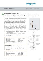
Screwing Units for Potentiometer Adjustment<br />
Automatic Screwing Unit<br />
The compact automatic Screwing Units enable potentiometer<br />
adjustment. The units are driven by means of a flexible shaft,<br />
which allows individual, compact mounting of the drive motor.<br />
The threaded section and the mounting holes in the housing<br />
enable multiple assembly possibilities in the Fixture.<br />
The Potentiometer Screwing Unit is designed modularly –<br />
offering problem-free adaption of the Unit in regard to the<br />
various Engraver tips and the special customer demands. The<br />
Engraver itself is spring-loaded.<br />
– Part No. 27791 Body of Potentiometer Screwing Unit<br />
– Part No. 27790 Replaceable Unit without insertable tip<br />
– I ndividual insertable tip on request<br />
Technical Data:<br />
Maximum Stroke: 4.0 mm, Applied<br />
Force by max. stroke: 1 N<br />
Further information can be found in our <strong>Accessories</strong> Catalog.<br />
Manual Screwing Unit<br />
Part No. 17049 Manual Screwing Unit for Potentiometer<br />
Adjustment ( Engraver: Cross-head with slot)<br />
Manual Key/Button activation<br />
Part No. 19637 Manual button/key activation<br />
Please note that the Engraver must be mounted vertical to the<br />
surface which is to be marked.<br />
The version with cutting Engraver has the identical design as the<br />
standard version (Part No. 24447).<br />
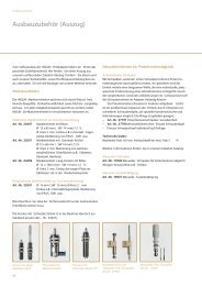
Short and long<br />
Marking Unit<br />
42<br />
Pneumatic Marking<br />
Unit<br />
Marking Unit with<br />
Cutting Engraver 35°<br />
Automatic and manual<br />
Potiometer Screwing Unit<br />
Part. No. 27791<br />
Manual Potiometer<br />
Screwing Unit<br />
Part. No. 17049
<strong>Customizing</strong> <strong>Accessories</strong><br />
Pylon Receiver<br />
The Pylon Receiver from INGU N can be loaded with all INGU N<br />
Interface Blocks.<br />
Interface Blocks<br />
Part No. 21329<br />
INGUN Receiver (Type Pylon) for<br />
PWB 170/INGUN (10 Contact<br />
Blocks) with extended contacting<br />
stroke (Handle can be assembled<br />
variably)<br />
Interface Blocks, loaded with INGU N Test Probes, guarantee best<br />
contacting quality and low contact resistance. Usage in Interface<br />
Blocks as e.g. Internal Intermediate Interface in the Fixture series<br />
MA 2111, 2112, 2113 as well as V IN 2040.<br />
High-current Pin Block max. 16<br />
A (34 pole), without photo (simi lar to<br />
High-current Pin Block 24 A)<br />
S-RC-034-16A<br />
Part No. 31011<br />
HSS-118 317 175 A 1502 M<br />
KS-112 30 M-R<br />
S-ATS-034-10<br />
Part No. 31009<br />
KT-254 L3 E02-30<br />
Optical Wave Guide Pin Block (45<br />
pole)<br />
S-RC-045-LWL<br />
Part No. 27618<br />
KS-004 35 G-K (without LWL)<br />
S-ATS-045-LWL<br />
Part No. 29448<br />
KS-004 35 G-K (without LWL)<br />
High-current Pin Block max. 50<br />
A (2 pole), without photo<br />
S-RC-002-50A<br />
Part No. 31549<br />
HSS-150 317 300 A 5002 M<br />
KS-150 M3 M3<br />
S-ATS-002-10<br />
Part No. 31550<br />
KT-150 L3 E02-M3<br />
Optical Wave Guide Pin Block<br />
(24 pole) (without loss, due to Spring<br />
Loaded wave<br />
guides (LWL)<br />
S-RC-024-LWL<br />
Part No. 30210<br />
KS inserted (without LWL)<br />
S-ATS-024-LWL<br />
Part No. 30211<br />
KS inserted (without LWL)<br />
Signal Pin Block (170 pole) Signal Pin Block max. 4 A (170<br />
pole) Low Ohm<br />
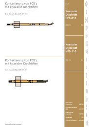
Radio-frequency Pin Block up to<br />
700 MHz (16 pole)<br />
Radio-frequency Pin Block up to<br />
2 GHz (15 pole)<br />
S-RC-170-4A<br />
Part No. 27616<br />
GKS-945 357 106 A 1100<br />
KS-945 47<br />
S-ATS-170-06<br />
Part No. 13515<br />
KT-158 06<br />
High-current Pin Block max. 16<br />
A (45 pole) Delivery status ( RC),<br />
unloaded, (Part No. 30962)<br />
S-RC-170-N-4A<br />
Part No. 31006<br />
HSS-118 317 175 A 1102<br />
KS-112 47<br />
S-ATS-170-06<br />
Part No. 13515<br />
KT-158 06<br />
High-current Pin Block max. 24<br />
A* (24 pole) (*24 A only possible<br />
when partly loaded)<br />
S-RC-016-700MHz*<br />
Part No. 31005<br />
HFS-110 307 100 A 3002 A<br />
KS-110 23 and SE-110 V<br />
S-ATS-016-2GHz*<br />
Part No. 31003<br />
KS-410<br />
SB-810 Z or<br />
SB-810 V<br />
(*unloaded, individually loaded)<br />
Pneumatic Pin Block (8 pole)<br />
S-RC-015-2GHz*<br />
Part No. 29444<br />
HFS-410 305 051 A 5006<br />
KS-410 and SE 810 V<br />
S-ATS-015-2GHz*<br />
Part No. 31489<br />
SB-810 Z or<br />
SB-810 V<br />
(*unloaded, individually loaded)<br />
S-RC-045-16A<br />
Part No. 30963<br />
HSS-120 317 300 A 1502 M<br />
KS-113 30 M2-R<br />
S-ATS-045-10<br />
Part No. 16900<br />
KT-120 L3 E02-30<br />
S-RC-024-24A<br />
Part No. 27628<br />
HSS-120 317 300 A 2202 M<br />
KS-113 30 M2-R<br />
S-ATS-024-10<br />
Part No. 27620<br />
KT-120 L3 E02-30<br />
S-RC-008-PK3<br />
Part No. 27630<br />
KSV-PK3<br />
S-ATS-008-PK3<br />
Part No. 27622<br />
KDV-PK3<br />
We will be pleased to provide<br />
individual Interface Blocks in<br />
accordance to your demands<br />
and requirements.<br />
43
<strong>Customizing</strong> <strong>Accessories</strong><br />
Contacting of Western Mini Plugs and USB Plugs<br />
For the wear-free contacting of Western Mini Plugs and USB<br />
Plugs INGU N offers especially manufactured mating parts, which<br />
are designed with robust copper-beryllium wires.<br />
Western-Mini Plugs<br />
Part No. 17824 Western-Mini Plug, 4-channels, FR 4 with<br />
CuBe Insert<br />
Part No. 17825 Western-Mini Plug, 6-channels<br />
Part No. 17826 Western-Mini Plug, 8-channels<br />
Part No. 17827 Western-Mini Plug, 10-channel s<br />
USB Test Plugs<br />
Part No. 17829<br />
USB Test Plug, 4-channels<br />
Mounting Shoes are available for the assembly of all Test<br />
Plugs.<br />
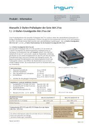
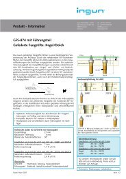
Spring-loaded Tooling Pins GFS-874<br />
To enable high-precision customizing INGU N also offers springloaded<br />
Tooling Pins. In this case the PC-Board sits on a conically<br />
shaped Tooling Pin Plunger. A Tooling Pin set is necessary for<br />
customizing. This set consists of one Tooling Pin with a conical-tip<br />
and one with a dagger-tip. More information can be found in our<br />
Fixture <strong>Accessories</strong> catalog.<br />
For Tooling Pin Holes:<br />
Ø 2.0 mm to Ø 3.5 mm<br />
Part No. 24481 conical-shaped<br />
Part No. 25214 dagger-shaped<br />
Tooling Pin Ø 3.98 mm<br />
For Tooling Pin Holes:<br />
Ø 3.5 to 5.5 mm<br />
Part No. 25215 conical-shaped<br />
Part No. 25217 dagger-shaped<br />
Tooling Pin Ø 5.98 mm<br />
Further special Tooling Pins are available such as e.g. with a disk<br />
or for In-line Systems (e.g. with optical safety check or springloaded).<br />
Further Plug variants available.<br />
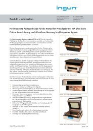
Tooling Pins<br />
2 + 0.01<br />
3 -0.05<br />
7 7<br />
(14)<br />
Rigid Tooling Pins<br />
The Tooling Pins from INGU N<br />
register the PC-Board in the<br />
applicable Tooling Pin Holes<br />
and guarantee an exact place -<br />
ment of the PC-Board on the<br />
Fixture. Tooling Pin diameters<br />
from 1.9 to 5 mm in steps<br />
of 0.1mm are available. The<br />
Tooling Pins have a tolerance<br />
of 0/+ 0.05 mm.<br />
Pushrods<br />
A large range of Pushrods is available to support the listed<br />
Pressure Frame Units and Cover systems. Furthermore the<br />
range of Pushrods also takes the various PCB thicknesses into<br />
consideration.<br />
Pushrods for MA-Series<br />
Part No. 19813 Pushrods for Pressure- Frame Plate,<br />
L = 51 mm, Head Ø 2.5 mm (1)<br />
Part No. 19815 Pushrods for Pressure- Frame Plate,<br />
L = 51 mm, Head Ø 6.0 mm (1)<br />
Part No. 21615 Pushrods, L = 60 mm, Head Ø 2.5 mm (2)<br />
Part No. 23190 Pushrods, L = 60 mm, Head Ø 4.0 mm (2)<br />
Part No. 18870 Pushrods, L = 60 mm, Head Ø 6.0 mm (2)<br />
Pushrods for Vacuum Fixtures<br />
Part No. 17324 Pushrods 55,6 rigid, green, Ø 2.5;<br />
L = 55.6 mm<br />
Part No. 19419 Pushrods 55,6 rigid, green, Ø 6.0;<br />
L = 55.6 mm<br />
Numerous other types on request.<br />
(1)<br />
e.g. for MA 2130/2135/PA 2130/PAZ 215/200<br />
(2)<br />
e.g. for MA 2111/2112/2113/2113 T<br />
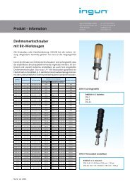
Western-Mini-Plugs<br />
44<br />
Spring-loaded Tooling Pin Set<br />
(Dagger / Conical)
<strong>Customizing</strong> <strong>Accessories</strong><br />
Vacuum-free Zone<br />
For customizing with Vacuum-free Zones INGUN offers tailormade<br />
sizes – both for single- and dual-stage customizing.<br />
Part No. 000512 Vacuum-free Zone made of silicone<br />
(single-stage); variable, manufacturing<br />
dimensions according to customer<br />
demands.<br />
Part No. 000513 Vacuum-free Zone made of silicone (dualstage);<br />
variable, manufacturing dimensions<br />
according to customer demands.<br />
Transfer Field<br />
The following contacting components are used in a Transfer Field.<br />
Note: The rigid Contact Terminals are normally mounted in the<br />
Pressure Frame Unit.<br />
Contact transfer: Transfer Field<br />
– Contact Terminal KT-254 W3 E12 with wire-wrap connection<br />
for Transfer Field (usage in upper Probe Plate)<br />
– Receptacle KS-100 47 with wire-wrap connection for Transfer<br />
Contact (usage in lower Probe Plate)<br />
– Test Probe GKS-100 307 150 A 1500 for Transfer Contact<br />
(assembly in Receptacle)<br />
– Contact Terminal KT-112 143 215 E02 variant with<br />
exchangeable KT: usage in Receptacle KS 112 47<br />
<strong>Customizing</strong> <strong>Accessories</strong> especially for Vacuum Fixtures<br />
Transfer Field<br />
KT-254 W3 E12 Contact Terminal with wire-wrap connection for Transfer Field (usage in upper Probe Plate)<br />
KS 100 47 Receptacle with wire-wrap connection. Receptacle for Transfer Contact (usage in lower Probe Plate)<br />
GKS 100 307 150 A 1500<br />
Test Probe for Transfer Contact (assembly in Receptacle)<br />
KT 112 143 215 E02<br />
Variant with exchangeable KT: usage in Receptacle KS 112 47<br />
Pushrods/Vacuum-free zone<br />
Part No. 17324 Pushrods 55.6 rigid, green, Ø 2.5 Length: 55.6 mm long<br />
Part No. 19419 Pushrods 55.6 rigid, green, Ø 6.0 Length: 55.6 mm long<br />
Part No. 000512 Vacuum-free Zone (single-stage) variable, length according to customer requirements<br />
Part No. 000513 Vacuum-free Zone (dual-stage) variable, length according to customer requirements<br />
Pushrods Part No.<br />
19813, 19815 and<br />
21615<br />
Pushrods Part No.<br />
17324 and 19419<br />
Vacuum-free Zone<br />
<strong>Customizing</strong> example of Approach Mechanism<br />
45
<strong>Customizing</strong> <strong>Accessories</strong><br />
Connector Approach Mechanisms<br />
Approach Mechanisms offer the possibility to contact connectors<br />
from the side. They can be additionally built into a Fixture and are<br />
favoured for wear-free contacting of connectors. Mechanically or<br />
pneumatically driven versions are available.<br />
Further Approach mechanisms are available on request (e.g.<br />
mechanically driven via an inclined plane – see page 52).<br />
Part No. 12306 SAM- E (Contacting Stroke 14 mm) Outside<br />
Dimensions: 200 x 70 x approx. 70 mm<br />
(w x d x h)<br />
Part No. 12559 SAM- DE (Contacting Stroke 14 mm) Outside<br />
Dimensions: 270 x 70 x approx. 70 mm<br />
(w x d x h)<br />
Part No. 26239 SAM Pneumatic incl. Solenoid Valve 12 V<br />
Contact Cleaning Mats<br />
Part No. 3254<br />
Part No. 3255<br />
Part No. 3256<br />
Part No. 8460<br />
Part No. 21092<br />
KR M 01 Outside Dimensions: 250 x 100 mm<br />
KR M 02 Outside Dimensions: 250 x 200 mm<br />
KR M 03 Outside Dimensions: 250 x 300 mm<br />
KR M 04 Outside Dimensions: 700 x 500 mm<br />
KR M 08 Outside Dimensions: on request<br />
PC-Boards often show signs of flux deposits and oxide layers,<br />
which cause contamination of the contact surface and subse -<br />
quently provide an insulating coating. The longer the Test Probes<br />
are used the greater the danger that the deposits remain on the<br />
test probe tips. In this case INGU N recommends the cleaning of<br />
the probe tips by means of a Contact Cleaning Mat. This method<br />
can be used especially by tip-styles that have a self-cleaning char -<br />
acter, e.g. tip-styles 01, 09, 15, 31, 38, 77, 91, 93, 97, 98.<br />
Contact Cleaning Mats can be used on all INGU N Fixtures<br />
that don’t have a Pressure Frame Unit. The Mats are available in<br />
various sizes.<br />
Further details – also regarding probe cleaning brushes – can<br />
be found in our <strong>Accessories</strong> catalog.<br />
Counter-pressure Springs<br />
Part No. 2785 FED 10/80/15.0<br />
Part No. 23818 FED 10/85/21.5 dual-stage Fixtures<br />
Part No. 1571 FED 10/90/16 <strong>Customizing</strong> VA<br />
2030/2040<br />
Part No. 1572 FED 14/80/22 dual-stage Fixtures<br />
Part No. 1569 FED 14/90/17.5<br />
Part No. 1584 FED D-090 W-01 Counter-pressure Spring<br />
for spring-loaded Mounting Plate for<br />
Manual Fixtures MA<br />
Placement supports / Pre-registration Pins<br />
Part No. 13781<br />
PCB Support Disks<br />
Part No. 3161<br />
Stroke limiting Disks<br />
Part No. 2579<br />
Pre-registration / Placement Supports<br />
made of Delrin 22 mm (h)<br />
Antistatic PCB Support Disk<br />
5 x 3 mm (d x h)<br />
HBS-KTP for assembly on Probe Plate of<br />
Vacuum Fixture<br />
Cleaning Mat<br />
Counter-pressure Springs<br />
Pre-registration Pins<br />
Part No. 13781<br />
PCB Support Disks<br />
Part No. 3161<br />
Stroke limiting Disk<br />
Part No. 2579<br />
46