Photovoltaic Solar Inverter Series ES - Effekta
Photovoltaic Solar Inverter Series ES - Effekta
Photovoltaic Solar Inverter Series ES - Effekta

You also want an ePaper? Increase the reach of your titles
YUMPU automatically turns print PDFs into web optimized ePapers that Google loves.
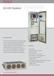
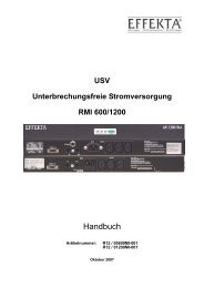
<strong>Photovoltaic</strong> <strong>Solar</strong> <strong>Inverter</strong> <strong>Series</strong> <strong>ES</strong><br />
<strong>ES</strong>2200 / <strong>ES</strong>3300 / <strong>ES</strong>4200 / <strong>ES</strong>5000<br />
Operating Manual V. 2.1 UK<br />
Artikelnummer SLWRABSI2K0WD000<br />
SLWRABSI3K0WD000<br />
SLWRABSI4K0WD000<br />
SLWRABSI5K0WD000
<strong>Photovoltaic</strong> <strong>Solar</strong> <strong>Inverter</strong> <strong>Series</strong> <strong>ES</strong> Legal Notice<br />
Legal Notice<br />
Copyright © 2009<br />
All rights reserved.<br />
The manual is protected by copyright law.<br />
EFFEKTA Regeltechnik GmbH possesses the copyright.<br />
All used trademarks are the property of their respective owners.<br />
EFFEKTA ® is a registered trademark of EFFEKTA Regeltechnik GmbH.<br />
EFFEKTA Regeltechnik GmbH<br />
Rheinwaldstraße 34<br />
78628 Rottweil, Germany<br />
July 2010<br />
We reserve the right to make technical and optical changes as well as printing errors.<br />
<strong>ES</strong> series 2
<strong>Photovoltaic</strong> <strong>Solar</strong> <strong>Inverter</strong> <strong>Series</strong> <strong>ES</strong> Safety and the Environment<br />
Safety and the Environment<br />
Avoid personal injury / property damage<br />
o Please read this operating manual carefully to familiarise yourself with the<br />
device.<br />
o In particular, heed the information regarding the installation and commis-<br />
sioning of the device.<br />
o Only operate the product in an appropriate and proper way and within the<br />
parameters stated in the Technical data.<br />
o Only perform maintenance and service work that is described in the<br />
documentation. Observe the required steps. Only use original replace-<br />
ment parts from EFFEKTA.<br />
Protecting the environment<br />
About this document<br />
Symbol /<br />
Image<br />
o Send the product back to EFFEKTA after the end of its useful life. We will<br />
ensure environmentally friendly disposal.<br />
o The abbreviation PV in this manual stands for photovoltaic.<br />
o Read this documentation carefully and make yourself familiar with the<br />
product before using it. Store this documentation in an easily accessible<br />
place to refer to it if necessary. Please pass this documentation on to later<br />
users of the product.<br />
o In this document, the following conventions are observed:<br />
Explanation / Example<br />
With the signal word Attention!:<br />
Warning of dangerous electrical voltage.<br />
<strong>ES</strong> series 3
�<br />
1<br />
<strong>Photovoltaic</strong> <strong>Solar</strong> <strong>Inverter</strong> <strong>Series</strong> <strong>ES</strong> Safety and the Environment<br />
With the signal word Attention!:<br />
Warns of dangers that could lead to serious physical injuries if the identified<br />
precautionary measures are not taken.<br />
With the signal word Caution!:<br />
Warns of dangers that could lead to slight physical injuries or property dam-<br />
age if the indicated precautionary measures are not taken.<br />
Identifies instructions, additional information and tips.<br />
Identifies instructions for recycling.<br />
Identifies components that are subject to the Electronic Scrap Regulation.<br />
Identifies components or parts that must be disposed. Do not throw these in<br />
the household waste.<br />
Requirement that must be fulfilled:<br />
� The DC circuit breaker is set to OFF.<br />
Steps are listed in numbers if a certain sequence of actions must be ob-<br />
served.<br />
<strong>ES</strong> series 4
<strong>Photovoltaic</strong> <strong>Solar</strong> <strong>Inverter</strong> <strong>Series</strong> <strong>ES</strong> Safety and the Environment<br />
�<br />
" ... "<br />
Bold text<br />
…>…<br />
[ ]<br />
<strong>ES</strong>C<br />
A step is not numbered if the action only involves one step or if the step is<br />
optional.<br />
Sample entries are in quotes:<br />
The value "0" causes the following...<br />
Elements on the programme surface or device display:<br />
The device description appears in File list of devices/parameters.<br />
Functions/paths within a menu:<br />
Start > All programmes > EFFEKTA > XYZ Software.<br />
Keys that cause an action to start:<br />
Confirm the entry with [OK].<br />
Keys on the device or keypad:<br />
Press <strong>ES</strong>C.<br />
<strong>ES</strong> series 5
Photovoltaik Wechselrichter Serie <strong>ES</strong> Table of Contents<br />
Table of Contents<br />
1. INTRODUCTION ........................................................................................... 8<br />
2. SAFETY ..................................................................................................... 9<br />
2.1 General safety instructions ...................................................................... 9<br />
2.2 Information about housing ..................................................................... 10<br />
2.3 Information about PV module ................................................................ 10<br />
2.4 Information about mains connection ...................................................... 11<br />
3. OVERVIEW OF PRODUCT ........................................................................... 12<br />
3.1 Dimensions ............................................................................................ 12<br />
3.2 Display and connections ........................................................................ 13<br />
4. INSTALLATION .......................................................................................... 14<br />
4.1 Checking the device and scope of delivery ........................................... 14<br />
4.2 Ambient conditions for installation ......................................................... 16<br />
4.3 Installation of the PV solar inverter ........................................................ 18<br />
5. ELECTRICAL INSTALLATION ...................................................................... 20<br />
5.1 Connecting AC power cable .................................................................. 20<br />
5.2 Connecting PV module .......................................................................... 24<br />
5.2.1 Requirements of PV module ..................................................... 24<br />
5.2.2 Attaching cables for PV module ................................................ 24<br />
5.2.3 Overview of cables for the PV module ...................................... 27<br />
6. CONTROL PANEL ...................................................................................... 28<br />
7. COMMISSIONING....................................................................................... 30<br />
7.1 Starting device for the first time ............................................................. 30<br />
7.2 Country settings, operating mode settings and ID settings ................... 31<br />
7.3 Commissioning the PV solar inverter ..................................................... 33<br />
7.4 Checking measurement readings and numbers .................................... 34<br />
7.5 Operating status of the PV solar inverter ............................................... 37<br />
8. COMMUNICATION INTERFAC<strong>ES</strong> .................................................................. 39<br />
8.1 Standard communication interface ........................................................ 39<br />
8.1.1 Settings for the RS-232 interface .............................................. 39<br />
8.1.2 Pin assignment for the RS-232 interface .................................. 39<br />
8.2 <strong>Solar</strong>-LogTM .......................................................................................... 39<br />
8.3 Optional data cards ................................................................................ 40<br />
<strong>ES</strong> series 6
Photovoltaik Wechselrichter Serie <strong>ES</strong> Table of Contents<br />
8.3.1 Installing communication card ................................................... 40<br />
8.3.2 RS-485 card .............................................................................. 42<br />
8.3.3 Connecting the RS 485 ............................................................. 43<br />
8.3.4 USB card ................................................................................... 45<br />
8.3.5 Relay contact of card (DCE-B card) .......................................... 46<br />
8.3.6 SNMP card ................................................................................ 47<br />
9. STATUS DIAGNOSIS AND TROUBL<strong>ES</strong>HOOTING ............................................ 48<br />
9.1 Error codes and explanations ................................................................ 48<br />
9.2 Mains error alarm codes and explanations ............................................ 51<br />
10. SERVICE .................................................................................................. 54<br />
11. TECHNICAL DATA ..................................................................................... 55<br />
11.1 Device specifications ............................................................................. 55<br />
11.2 Block diagram of <strong>ES</strong>2200 / <strong>ES</strong>3300 ...................................................... 58<br />
11.3 <strong>ES</strong>4200 / <strong>ES</strong>5000 Block diagram .......................................................... 59<br />
11.4 Scope of delivery / (optional) accessories ............................................. 60<br />
12. DECLARATION OF CONFORMITY ................................................................ 63<br />
13. WARRANTY AND LIABILITY ........................................................................ 64<br />
13.1 Warranty conditions ............................................................................... 64<br />
13.2 Limitation of liability ................................................................................ 65<br />
<strong>ES</strong> series 7
<strong>Photovoltaic</strong> <strong>Solar</strong> <strong>Inverter</strong> <strong>Series</strong> <strong>ES</strong> Introduction<br />
1. Introduction<br />
Thank you for deciding to purchase a photovoltaic solar inverter from the <strong>ES</strong><br />
series.<br />
Many years of experience in the production of power supply devices have gone<br />
into the construction of this device. We hope that this device supports your so-<br />
lar system for many years without a glitch.<br />
The PV solar inverter is a complex electronic system that must deal with many<br />
regional supply conditions. If you have questions about this, or if faulty opera-<br />
tion occurs, please do not hesitate to contact your authorised dealer. He will try<br />
to help you as quickly and easily as possible.<br />
<strong>ES</strong> series 8
<strong>Photovoltaic</strong> <strong>Solar</strong> <strong>Inverter</strong> <strong>Series</strong> <strong>ES</strong> Safety<br />
2. Safety<br />
2.1 General safety instructions<br />
This operating manual contains important instructions that you must follow dur-<br />
ing the installation and operation.<br />
For this reason, please read and heed the operating manual and the safety in-<br />
structions provided in this chapter before you take any additional steps.<br />
Work on the device is to be performed solely by authorised professional staff.<br />
Attention!<br />
Faulty operation and incorrectly performed work can cause serious injuries<br />
and property damage.<br />
The installation of your PV solar inverter in accordance with the respective<br />
requirements may only be handled by authorised professional staff.<br />
Attention! Danger of electric shock<br />
Do not perform any work on the PV solar inverter if this work is not described<br />
in this operating manual.<br />
The PV solar inverter contains capacitors. These require at least 12 minutes<br />
to be discharged to a safe level if the supply of power is interrupted.<br />
Attention! Danger of burns<br />
Some components of this device can reach high temperatures.<br />
Do not touch these components!<br />
<strong>ES</strong> series 9
<strong>Photovoltaic</strong> <strong>Solar</strong> <strong>Inverter</strong> <strong>Series</strong> <strong>ES</strong> Safety<br />
2.2 Information about housing<br />
Attention!: Danger of electric shock<br />
Only open the covers of the connections on the PV solar inverter when the<br />
device has been separated from the supply of electricity and has no voltage.<br />
The covers and the housing may only be opened by authorised professional<br />
staff.<br />
2.3 Information about PV module<br />
Before you connect the PV module, check whether the voltage parameters in<br />
the manufacturer's Technical data correspond to the actual parameters.<br />
When reading the voltage, be sure that the PV module achieves a higher open<br />
circuit voltage at lower temperatures and unchanged solar radiation.<br />
At -20 °C, the open circuit voltage of the PV module may not be above 500 V.<br />
To determine the theoretical open circuit voltage at -20 °C, use the tempera-<br />
ture factors in the data sheet of the PV module.<br />
If the open circuit voltage of the PV module is over 500 V, the PV module<br />
may not be connected since the warranty is forfeited in such cases.<br />
The PV solar inverter contains a monitoring unit for fault currents in accor-<br />
dance with VDE 0126-1-1. This unit measures the ground current of the PV<br />
module and prevents a feeding into the mains in the event of a ground fault.<br />
<strong>ES</strong> series 10
<strong>Photovoltaic</strong> <strong>Solar</strong> <strong>Inverter</strong> <strong>Series</strong> <strong>ES</strong> Safety<br />
2.4 Information about mains connection<br />
The PV solar inverter may only be connected to the mains by appropriately li-<br />
censed specialists.<br />
Please contact your regional energy supplier with regard to special require-<br />
ments.<br />
Permission from the energy provider/supplier must be obtained for the connec-<br />
tion of the PV solar inverter.<br />
<strong>ES</strong> series 11
<strong>Photovoltaic</strong> <strong>Solar</strong> <strong>Inverter</strong> <strong>Series</strong> <strong>ES</strong> Overview of product<br />
3. Overview of product<br />
3.1 Dimensions<br />
<strong>ES</strong>2200/3300 <strong>ES</strong> 4200/5000<br />
Width W [mm] 455 455<br />
Height H [mm] 430 510<br />
Depth D [mm] 190 190<br />
<strong>ES</strong> series 12
<strong>Photovoltaic</strong> <strong>Solar</strong> <strong>Inverter</strong> <strong>Series</strong> <strong>ES</strong> Overview of product<br />
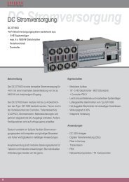
3.2 Display and connections<br />
<strong>ES</strong> 4200/5000<br />
1 Control panel with LCD & LED<br />
displays<br />
2 Interface to<br />
data transmission (option)<br />
3 Output terminal for alternating<br />
current<br />
4 Interface to<br />
data transmission (standard)<br />
5 Interface for emergency<br />
shutdown<br />
Operation & display of operating<br />
state of PV solar inverter<br />
USB, RS-485, floating contact,<br />
TCP/IP<br />
Alternating current output connection<br />
to power grid<br />
RS-232<br />
EPO<br />
6 Feed for PV module Plug and socket for the connection<br />
of the solar module:<br />
<strong>ES</strong> 2200: 3 connections (1 MPPT)<br />
<strong>ES</strong> 3300: 3 connections (1 MPPT)<br />
<strong>ES</strong> 4200: 3 connections (2 MPPT)<br />
<strong>ES</strong> 5000: 3 connections (2 MPPT)<br />
<strong>ES</strong> series 13
<strong>Photovoltaic</strong> <strong>Solar</strong> <strong>Inverter</strong> <strong>Series</strong> <strong>ES</strong> Installation<br />
4. Installation<br />
Please read the chapter "Safety" on page 9 before connecting the PV solar<br />
inverter.<br />
4.1 Checking the device and scope of delivery<br />
Check the completeness of the package and the device for any damage after<br />
receiving the PV solar inverter. Although the manufacturer ensures a safe<br />
packaging of the product, damage can nonetheless occur during transport. In-<br />
form the transport company and your dealer about damage that has occurred.<br />
The packaging of the PV solar inverter can be recycled.<br />
Save the packaging for future use or dispose of it accordingly.<br />
The standard delivery for a PV solar inverter consists of:<br />
o 1 PV solar inverter<br />
o 1 operating manual<br />
o 1 set of PV connectors<br />
o 1 set of sealing caps for the PV connection<br />
o 1 wall mounting<br />
<strong>ES</strong> series 14
<strong>Photovoltaic</strong> <strong>Solar</strong> <strong>Inverter</strong> <strong>Series</strong> <strong>ES</strong> Installation<br />
Dimensions for wall mounting:<br />
PV solar inverter <strong>ES</strong>2200 / <strong>ES</strong>3300<br />
PV solar inverter <strong>ES</strong>4200 / <strong>ES</strong>5000<br />
<strong>ES</strong> series 15
<strong>Photovoltaic</strong> <strong>Solar</strong> <strong>Inverter</strong> <strong>Series</strong> <strong>ES</strong> Installation<br />
4.2 Ambient conditions for installation<br />
When selecting the installation site, please consider the weight of the PV<br />
solar inverter; see chapter "Technical data“ on page 55.<br />
Install the PV solar inverter only at locations that can bear this load.<br />
To guarantee perfect operation and a long service life, install the PV solar in-<br />
verter in accordance with the following requirements.<br />
o Select the coolest possible location for installation.<br />
High temperatures hamper the effectiveness and shorten the service life<br />
of the PV solar inverter. If need be, install an additional cooling system in<br />
the room in which the PV solar inverter is installed.<br />
o The PV solar inverter ambient temperature must range from - 25 °C to +<br />
50 °C.<br />
o The PV solar inverter may not be exposed to any direct solar radiation.<br />
<strong>ES</strong> series 16
<strong>Photovoltaic</strong> <strong>Solar</strong> <strong>Inverter</strong> <strong>Series</strong> <strong>ES</strong> Installation<br />
o The PV solar inverter is constructed for vertical assembly.<br />
Never assemble the PV solar inverter in a horizontal position and make<br />
sure it does not tilt forward if assembled outdoors.<br />
o When selecting the assembly location for the PV solar inverter, you must<br />
ensure that sufficient heat dissipation is possible.<br />
The following minimum amounts of free space around the PV solar in-<br />
verter must be maintained:<br />
<strong>ES</strong> series 17
<strong>Photovoltaic</strong> <strong>Solar</strong> <strong>Inverter</strong> <strong>Series</strong> <strong>ES</strong> Installation<br />
4.3 Installation of the PV solar inverter<br />
Use the supplied wall mounting for the installation of the PV solar inverter.<br />
For vertical installation, heed the weight of the PV solar inverter when select-<br />
ing the material to which it will be attached; see chapter "Technical data” on<br />
page 55.<br />
You can use the wall mounting to mark the holes for drilling. If you do not<br />
want to use the wall mounting as a template for the drill holes, please note the<br />
dimensions of the wall mounting in chapter "Checking the device and scope<br />
of delivery“ on page 14.<br />
To mount the PV solar inverter, proceed as follows:<br />
1 Mark the positions for the drill holes on the wall.<br />
2 Drill the holes in accordance with the screws you have selected.<br />
3 Screw on the wall mounting.<br />
<strong>ES</strong> series 18
<strong>Photovoltaic</strong> <strong>Solar</strong> <strong>Inverter</strong> <strong>Series</strong> <strong>ES</strong> Installation<br />
4 Hang the PV solar inverter on the wall mounting.<br />
Use the upper carrier plate so that the PV solar inverter cannot slip.<br />
5 Check whether the PV solar inverter is safely attached to the mounting.<br />
<strong>ES</strong> series 19
<strong>Photovoltaic</strong> <strong>Solar</strong> <strong>Inverter</strong> <strong>Series</strong> <strong>ES</strong> Electrical installation<br />
5. Electrical installation<br />
Attention! Danger of electric shock<br />
The system contains components with high voltage and high current. For this<br />
reason, improper handling can lead to accidents with deadly consequences or<br />
property damage.<br />
Wiring of PV solar inverter Example (<strong>ES</strong>4200/5000<br />
5.1 Connecting AC power cable<br />
Connection conditions<br />
o Heed the connection conditions of your mains operator.<br />
o Pay attention to the locally required country settings on the PV solar<br />
inverter; see chapter "Country settings, operating mode settings and ID<br />
settings on page 31.<br />
<strong>ES</strong> series 20
<strong>Photovoltaic</strong> <strong>Solar</strong> <strong>Inverter</strong> <strong>Series</strong> <strong>ES</strong> Electrical installation<br />
Ground fault circuit breaker<br />
The PV solar inverter is equipped with an integrated fault current monitoring<br />
unit.<br />
If an external RCD or FI circuit breaker is required, please use a type B circuit<br />
breaker which triggers above a 100 mA fault current.<br />
Cable line layout<br />
o The mains line resistance should not exceed 0.1 Ω.<br />
o Your electricity supplier must calculate the maximum line lengths after<br />
taking the cross section of the line into consideration.<br />
The following cable sizes are recommended for the AC power cables:<br />
Model Line cross section<br />
<strong>ES</strong>2200 / <strong>ES</strong>3300 4 mm 2<br />
<strong>ES</strong>4200 / <strong>ES</strong>5000 6 mm 2<br />
Overview of the cable lines<br />
<strong>ES</strong> series 21
<strong>Photovoltaic</strong> <strong>Solar</strong> <strong>Inverter</strong> <strong>Series</strong> <strong>ES</strong> Electrical installation<br />
To connect the AC cable, please proceed as follows:<br />
1 Measure the voltage and frequency of the supply mains.<br />
Supply voltage and frequency can vary from country to country.<br />
2 Make sure that AC and DC circuit breakers are in the OFF position before<br />
you attach the cables to the PV solar inverter.<br />
Don't turn on this switch before you have completely attached the cables.<br />
3 Loosen the screws of the cable inlet and remove it.<br />
4 Insert the supply cable through the cable inlet and<br />
connect the wires as indicated on the splitter:<br />
<strong>ES</strong> series 22
<strong>Photovoltaic</strong> <strong>Solar</strong> <strong>Inverter</strong> <strong>Series</strong> <strong>ES</strong> Electrical installation<br />
L<br />
N<br />
PE<br />
Conductor<br />
Neutral<br />
Grounding conductor (yellow-<br />
green)<br />
Attention! Danger of electric shock<br />
The absence of grounding can lead to dangerous electric shocks.<br />
Make sure that the grounding conductor is correctly connected before you start<br />
operating the PV solar inverter.<br />
5 Position the cable inlet and screw it to the housing of the PV solar in-<br />
verter.<br />
<strong>ES</strong> series 23
<strong>Photovoltaic</strong> <strong>Solar</strong> <strong>Inverter</strong> <strong>Series</strong> <strong>ES</strong> Electrical installation<br />
5.2 Connecting PV module<br />
5.2.1 Requirements of PV module<br />
The PV solar inverters <strong>ES</strong>4200 and <strong>ES</strong>5000 use 2 MPP trackers. Tracker A<br />
can be connected to up to 2 strings and Tracker B can be conected to one<br />
string.<br />
The PV solar inversters <strong>ES</strong>2200 and <strong>ES</strong>3300 have only one Tracker, that can<br />
be connected to up to 3 strings. The maximum DV input voltage of 500V and<br />
the maximum input current must not be exceeded.<br />
The connection cable of the PV module must be designed for these connec-<br />
tions.<br />
A set of connectors for connecting the line ends of a string is included in the<br />
scope of delivery. The type descriptions for other PV connectors are:<br />
o Connection plug: PV-KST4/6II-UR<br />
o Coupling connector: PV-KBT4/6II-UR<br />
You will find more information online at www.multi-contact.com.<br />
5.2.2 Attaching cables for PV module<br />
The PV solar inverter is equipped with PV quick connecting terminals. These<br />
permit the connection of up to two strings for <strong>ES</strong>2200 and <strong>ES</strong>3300 and up to<br />
three strings for <strong>ES</strong>4200 and <strong>ES</strong>5000.<br />
The connection of additional strings is possible. These must be externally<br />
connected.<br />
<strong>ES</strong> series 24
<strong>Photovoltaic</strong> <strong>Solar</strong> <strong>Inverter</strong> <strong>Series</strong> <strong>ES</strong> Electrical installation<br />
PV quick connections<br />
Attention! Danger of electric shock<br />
Make sure that the DC circuit breaker is located in the position OFF before<br />
you connect the PV module.<br />
Attention! Danger of property damage<br />
In determining the required panels in the PV string, please consider the follow-<br />
ing points:<br />
o To avoid damage to the PV solar inverter, make sure that the output on<br />
the PV module is never above 500 VDC.<br />
Make sure that the maximum open circuit voltage UOC of each PV string<br />
is less than 500 VDC. Voltage of over 500 VDC may damage the PV solar<br />
inverter.<br />
o Make sure that the short circuit current of the module is not greater than<br />
the measurement on the PV solar inverter.<br />
o To achieve the maximum energy output from your PV module, make sure<br />
that the voltage does not fall below 150 VDC at maximum Mpp perform-<br />
ance or exceed 450 VDC.<br />
o The following applies for the PV solar inverters <strong>ES</strong>4200 and <strong>ES</strong>500: To<br />
achieve the greatest effectiveness, both trackers should be laid out<br />
roughly symmetrically for the purpose of performance.<br />
o Within one tracker, only modules of the same type with the same power<br />
can be used.<br />
Important: For <strong>ES</strong>4200 and <strong>ES</strong>5000 the best efficiency will be obtained<br />
when both trackers have symmetric power confguration.<br />
<strong>ES</strong> series 25
<strong>Photovoltaic</strong> <strong>Solar</strong> <strong>Inverter</strong> <strong>Series</strong> <strong>ES</strong> Electrical installation<br />
To connect the PV module to the PV solar inverter, proceed as follows:<br />
1 Test whether the generator terminals have the correct polarity and do not<br />
exceed the maximum voltage for each string.<br />
2 Connect the positive (+) wire of the PV string 1 to the positive quick con-<br />
nection terminal on the PV solar inverter.<br />
3 Connect the negative (-) wire of the PV string 1 to the negative quick con-<br />
nection terminal on the PV solar inverter.<br />
o Repeat steps 2 and 3 for other PV strings.<br />
4 Check whether all wires and contacts have been connected correctly.<br />
5 Cover the unused sockets of the DC input with the supplied protective<br />
caps.<br />
<strong>ES</strong> series 26
<strong>Photovoltaic</strong> <strong>Solar</strong> <strong>Inverter</strong> <strong>Series</strong> <strong>ES</strong> Electrical installation<br />
5.2.3 Overview of cables for the PV module<br />
Overview of cable lines with two strings (<strong>ES</strong>4200, <strong>ES</strong>5000 via 4-pole DC<br />
breaker for respectively one string at tracker A or B.<br />
Overview of cable lines with one string for <strong>ES</strong>4200 or <strong>ES</strong>5000 in parallel<br />
mode via 2-pole DC breaker (all modules are mounted to one string before<br />
connected to the DC-breaker.<br />
In connecting with only one string, you must switch the operating mode in the<br />
configuration to "Parallel"; see chapter "Country settings, operating mode<br />
settings and ID settings on page 31.<br />
Be aware that <strong>ES</strong>2200/3300 offer only one tracker with connectors for three<br />
identical strings (internal parallel). If you connenct single strings separately you<br />
need a corresponding DC-breaker for more strings (4-pole / 6-pole).<br />
<strong>ES</strong> series 27
<strong>Photovoltaic</strong> <strong>Solar</strong> <strong>Inverter</strong> <strong>Series</strong> <strong>ES</strong> Control panel<br />
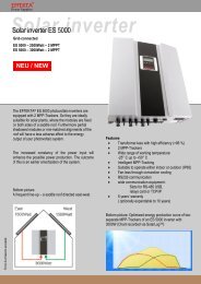
6. Control panel<br />
1 LCD display<br />
LINE Power source<br />
Service operation<br />
<strong>Solar</strong> cells<br />
Flow chart of the PV solar inverter in operation<br />
4-digit measurement display<br />
<strong>ES</strong> series 28
<strong>Photovoltaic</strong> <strong>Solar</strong> <strong>Inverter</strong> <strong>Series</strong> <strong>ES</strong> Control panel<br />
2 LED display<br />
3 Operating keys<br />
Red LED lights up constantly - indicates a ground fault or<br />
an isolation fault at the DC input.<br />
Yellow LED lights up constantly - indicates that the supply<br />
(voltage, frequency, etc.) does not correspond to the en-<br />
tered standard of the PV solar inverter.<br />
o Green LED lights up constantly - indicates that the<br />
performance of the solar cells is greater than 5 % of<br />
the nominal performance of the solar inverter.<br />
o Green LED blinks - indicates that the performance of<br />
the solar cells is less than 5 % of the nominal per-<br />
formance of the PV solar inverter.<br />
Confirm a change to the settings of the PV solar inverter.<br />
Continue to next page or change the settings of the PV<br />
solar inverter.<br />
Return to the previous page or change the settings of the<br />
PV solar inverter.<br />
Special function Log in / Log out.<br />
<strong>ES</strong> series 29
<strong>Photovoltaic</strong> <strong>Solar</strong> <strong>Inverter</strong> <strong>Series</strong> <strong>ES</strong> Commissioning<br />
7. Commissioning<br />
Attention! Danger of electric shock<br />
Check the following points before you start up the PV solar inverter:<br />
o The housing is safely screwed in place.<br />
o The DC cables (PV strings) are correctly connected and that unused DC<br />
connection terminals on the bottom of the housing are covered with safety<br />
caps.<br />
o The AC cable is connected correctly.<br />
o The AC switch is OFF.<br />
7.1 Starting device for the first time<br />
Display A<br />
Display B1<br />
1 Switch on the voltage of the PV string by turning on the DC circuit<br />
breaker.<br />
The PV solar inverter starts automatically when the voltage reaches 120<br />
VDC. All LEDs light up. The following is shown on the LCD display:<br />
After 3 seconds the LCD display changes from Display A to Display B1 (DC<br />
voltage) and Display B2 (alarm code).<br />
The green LED blinks to indicate that the output performance of the alternating<br />
current is below 5 % of the nominal performance.<br />
The yellow LED lights up constantly and indicates no power.<br />
<strong>ES</strong> series 30
<strong>Photovoltaic</strong> <strong>Solar</strong> <strong>Inverter</strong> <strong>Series</strong> <strong>ES</strong> Commissioning<br />
Display B2<br />
7.2 Country settings, operating mode settings and ID<br />
settings<br />
IMPORTANT!<br />
SETTINGS ALREADY CONFIGURED IN FACTORY.<br />
CHANG<strong>ES</strong> ONLY TO BE MADE USING LAPTOP AND SETTING TOOL.<br />
Caution! Danger of property damage<br />
False country settings can compromise your mains electricity, cause the solar<br />
inverter to malfunction and lead to the termination of your authorisation to<br />
operate the device.<br />
IMPORTANT!<br />
Before changing the settings assure that the AC switch is OFF.<br />
<strong>ES</strong> series 31
<strong>Photovoltaic</strong> <strong>Solar</strong> <strong>Inverter</strong> <strong>Series</strong> <strong>ES</strong> Commissioning<br />
This page is intentionally left blank.<br />
<strong>ES</strong> series 32
<strong>Photovoltaic</strong> <strong>Solar</strong> <strong>Inverter</strong> <strong>Series</strong> <strong>ES</strong> Commissioning<br />
7.3 Commissioning the PV solar inverter<br />
Display C1<br />
Display C2<br />
Display D<br />
Display E<br />
1 Check whether the DC circuit breaker is switched on and set it to ON if<br />
need be.<br />
2 Set the AC circuit breaker to ON.<br />
3 Wait 30 seconds (legally required waiting period).<br />
The LCD display changes between the Displays C1 (DC voltage) and Dis-<br />
play C2 (alarm code). The yellow LED lights up and the green LED blinks.<br />
After 30 seconds, the yellow LED goes off and the green LED blinks<br />
again. The LCD display shows Display D.<br />
After 5 seconds, the LCD display shows Display E. The green LED lights<br />
up constantly.<br />
<strong>ES</strong> series 33
<strong>Photovoltaic</strong> <strong>Solar</strong> <strong>Inverter</strong> <strong>Series</strong> <strong>ES</strong> Commissioning<br />
Display F<br />
If the PV solar inverter is defective (short circuit), an error code or the error<br />
status will appear on the display.<br />
Information!<br />
A list with the explanations of possible error codes can be found under "Error<br />
codes and explanations“ on page 48.<br />
If the PV solar inverter was started completely and successfully, the LCD<br />
display shows Display E.<br />
7.4 Checking measurement readings and numbers<br />
Display G:<br />
Voltage of String A<br />
Display H:<br />
Voltage of String B<br />
Display I:<br />
Current of String A<br />
Via the LCD display, you can check the measurement readings and numbers<br />
set by the PV solar inverter.<br />
o Use the key and the key to switch the displays.<br />
The measurement readings and numbers appear in the following order as<br />
you scroll down:<br />
<strong>ES</strong> series 34
<strong>Photovoltaic</strong> <strong>Solar</strong> <strong>Inverter</strong> <strong>Series</strong> <strong>ES</strong> Commissioning<br />
Display J:<br />
Current of String B<br />
Display K:<br />
Output power of<br />
String A<br />
Display L:<br />
Output power of<br />
String B<br />
Display M:<br />
PV solar inverter<br />
Output voltage<br />
Display N:<br />
Frequency of<br />
PV solar inverter<br />
Output voltage<br />
Display O:<br />
PV solar inverter<br />
Output current<br />
Display P:<br />
Current<br />
flow of energy<br />
Display Q:<br />
Total<br />
flow of energy<br />
<strong>ES</strong> series 35
<strong>Photovoltaic</strong> <strong>Solar</strong> <strong>Inverter</strong> <strong>Series</strong> <strong>ES</strong> Commissioning<br />
Display R:<br />
PV solar inverter<br />
Internal temperature<br />
°F<br />
Display S:<br />
PV solar inverter<br />
Internal temperature<br />
°C<br />
Display T:<br />
Temperature of<br />
cooling element °F<br />
Display U:<br />
Temperature of<br />
cooling element °C<br />
<strong>ES</strong> series 36
<strong>Photovoltaic</strong> <strong>Solar</strong> <strong>Inverter</strong> <strong>Series</strong> <strong>ES</strong> Commissioning<br />
7.5 Operating status of the PV solar inverter<br />
Operating<br />
state<br />
The PV solar inverter starts automatically when the DC power of the PV panel<br />
is sufficient.<br />
After starting, the PV solar inverter can exhibit the following operating states.<br />
Display on the<br />
LCD display<br />
Explanation<br />
Normal The PV solar inverter works<br />
normally.<br />
When the delivered performance<br />
of the PV panel is sufficient<br />
(500 VDC > PV >120 VDC), it<br />
supplies the energy to the<br />
mains.<br />
The green LED lights up and<br />
shows that energy is being fed<br />
into the mains.<br />
Standby If the performance is insufficient<br />
(60VDC < PV < 100VDC), the PV<br />
solar inverter switches to<br />
standby operation and searches<br />
for a connection to the mains.<br />
It has only limited power from<br />
the PV module to monitor the<br />
internal system state.<br />
Error The internal regulator continually<br />
monitors the system state and<br />
adjusts it.<br />
If the PV solar inverter registers<br />
malfunctions such as mains<br />
problems or internal errors, the<br />
display will this, and the red LED<br />
will light up.<br />
EPO Emergency power off (EPO).<br />
The solar inverter does not<br />
receive any power from the<br />
mains in this state.<br />
<strong>ES</strong> series 37
<strong>Photovoltaic</strong> <strong>Solar</strong> <strong>Inverter</strong> <strong>Series</strong> <strong>ES</strong> Commissioning<br />
Operating<br />
state<br />
Shut down<br />
process<br />
Display on the<br />
LCD display<br />
Explanation<br />
No display If there is too little sunlight, the<br />
PV solar inverter automatically<br />
ends operation.<br />
It does not receive any power<br />
from the mains. The display and<br />
the LEDs on the control panel<br />
are out of operation.<br />
<strong>ES</strong> series 38
<strong>Photovoltaic</strong> <strong>Solar</strong> <strong>Inverter</strong> <strong>Series</strong> <strong>ES</strong> Communication interfaces<br />
8. Communication interfaces<br />
You can connect external devices to the PV solar inverter and call up data. The<br />
various communication interfaces are designed for this.<br />
8.1 Standard communication interface<br />
The standard communication interface for the PV solar inverter consists of a<br />
RS-232 serial interface (otherwise described as EIA-232).<br />
8.1.1 Settings for the RS-232 interface<br />
The RS-232 interface is set as follows:<br />
o Baud rate: 9600 bps<br />
o Data length: 8 Bit<br />
o Stop bit: 1 Bit<br />
o Parity: None<br />
8.1.2 Pin assignment for the RS-232 interface<br />
8.2 <strong>Solar</strong>-LogTM<br />
Pin 3: RS-232 Rx<br />
Pin 2: RS-232 Tx<br />
Pin 5: GND<br />
EFFEKTA <strong>Solar</strong> inverters can operate with <strong>Solar</strong>-Log TM . Ask our sales dpt. and<br />
service for more information.<br />
<strong>ES</strong> series 39
<strong>Photovoltaic</strong> <strong>Solar</strong> <strong>Inverter</strong> <strong>Series</strong> <strong>ES</strong> Communication interfaces<br />
8.3 Optional data cards<br />
If you need other interfaces than the standard communication interface, you<br />
can install an optional communication card.<br />
ATTENTION!<br />
The data cards can only be mounted, while the inverter is swiched off! Mount-<br />
ing the data cards during operating mode can destroy the inverter.<br />
8.3.1 Installing communication card<br />
1 Loosen the screws and open the cover of the housing.<br />
2 Insert the data cable through the cable inlet of the cover.<br />
<strong>ES</strong> series 40
<strong>Photovoltaic</strong> <strong>Solar</strong> <strong>Inverter</strong> <strong>Series</strong> <strong>ES</strong> Communication interfaces<br />
3 Connect the data cable to the communication card.<br />
4 Insert the communication card in the receiver.<br />
5 Place the cover back on top and tighten the four screws evenly.<br />
<strong>ES</strong> series 41
<strong>Photovoltaic</strong> <strong>Solar</strong> <strong>Inverter</strong> <strong>Series</strong> <strong>ES</strong> Communication interfaces<br />
8.3.2 RS-485 card<br />
CN1 is determined for the terminating resistor.<br />
You can activate the function with Pin 1-2 and deactivate with Pin 2-3.<br />
CN2 is intended for RS-485 and CN3 for remote start-up.<br />
Definition:<br />
<strong>ES</strong> series 42
<strong>Photovoltaic</strong> <strong>Solar</strong> <strong>Inverter</strong> <strong>Series</strong> <strong>ES</strong> Communication interfaces<br />
8.3.3 Connecting the RS 485<br />
1. different inverters on one PC<br />
Jumper: ferrule<br />
resistor to „on“<br />
2. different inverters with <strong>Solar</strong>-Log TM<br />
Jumper: ferrule<br />
resistor to „on“<br />
<strong>ES</strong> series 43
<strong>Photovoltaic</strong> <strong>Solar</strong> <strong>Inverter</strong> <strong>Series</strong> <strong>ES</strong> Communication interfaces<br />
3. connected to a RS485 card (first inverter)<br />
4. connected to a RS485 card (different inverters)<br />
Shielding only<br />
one side to PE<br />
Note!<br />
4-core, twisted<br />
pair, shielded<br />
cable<br />
Nothing must be<br />
connected here!<br />
Free<br />
4-core, twisted pair,<br />
shielded cable<br />
Shielding only<br />
one side to PE<br />
4-core, twisted<br />
pair, shielded<br />
cable<br />
Shielding to PE<br />
Using several inverters the RS485 – Bus ill be looped through the different<br />
inverters. The bus-lines D-, D+ and GND (incomming and outgoing) are con-<br />
nected parallel to the terminals of the RS485-card. The shielding of the bus<br />
cables must be connected to the PE of the inverter case with only one end.<br />
<strong>ES</strong> series 44
<strong>Photovoltaic</strong> <strong>Solar</strong> <strong>Inverter</strong> <strong>Series</strong> <strong>ES</strong> Communication interfaces<br />
8.3.4 USB card<br />
Definition:<br />
o Compatible USB version 1.0, 1.5Mbit/s<br />
o Compatible HID Version 1.0<br />
Pin assignment for USB card:<br />
1: VCC (+5V)<br />
2: D –<br />
3: D +<br />
4: GND<br />
<strong>ES</strong> series 45
<strong>Photovoltaic</strong> <strong>Solar</strong> <strong>Inverter</strong> <strong>Series</strong> <strong>ES</strong> Communication interfaces<br />
8.3.5 Relay contact of card (DCE-B card)<br />
The pin assignment for the 10 pin terminal:<br />
Pin 1: DC input voltage inside and DC input voltage below<br />
the range<br />
Pin 2: at lest one DC input beyond the min. limit<br />
Pin 3: all DC input voltages below min. limit<br />
Pin 4: Frequency of AC output (network) out of tolerance<br />
Pin 5: island solution switched off<br />
Pin 6: Output current of the inverter above the tolerance<br />
Pin 7: The heat sink temperature of the inverter is too high<br />
Pin 8: Common<br />
Each relay contact can bear a load of max 40 VDC / 25 mA.<br />
You can switch over the output signal from N.C. (normal close)<br />
to N.O. (normal open) by bridging Pin 1 and 2 or Pin 2 and 3<br />
from JP1-5 with the jumpers.<br />
<strong>ES</strong> series 46
<strong>Photovoltaic</strong> <strong>Solar</strong> <strong>Inverter</strong> <strong>Series</strong> <strong>ES</strong> Communication interfaces<br />
8.3.6 SNMP card<br />
You will find more information and installation information in the documents that<br />
accompany the SNMP card.<br />
<strong>ES</strong> series 47
<strong>Photovoltaic</strong> <strong>Solar</strong> <strong>Inverter</strong> <strong>Series</strong> <strong>ES</strong> Status diagnosis and troubleshooting<br />
9. Status diagnosis and troubleshooting<br />
The PV solar inverter is equipped with a self-diagnosis system that identifies a<br />
large number of possible operating conditions independently and shows them<br />
on the LCD display. This makes it possible to quickly eliminate technical prob-<br />
lems.<br />
Furthermore, a distinction is possible between<br />
o service codes concerning installation and<br />
o service codes that relate internally to the PV solar inverter.<br />
Whenever the self-diagnosis system identifies a particular problem, the corre-<br />
sponding service code is showed on the LCD display.<br />
Information!<br />
The following work may only be performed by trained technical staff.<br />
9.1 Error codes and explanations<br />
LCD<br />
display<br />
Description Explanation Troubleshooting<br />
Er00 DC _BUS<br />
pre-charge defect<br />
Er03 <strong>Inverter</strong> voltage<br />
abnormal<br />
Er07 DC_BUS<br />
over-voltage<br />
Er08 DC_BUS<br />
under-voltage<br />
Er19 DC_BUS<br />
discharge defect<br />
Er22 Output relay<br />
defect<br />
The device is in the soft<br />
start mode, but after 2<br />
seconds you do not see<br />
any stable charging voltage<br />
on the DC bus.<br />
The output voltage is not<br />
correct.<br />
The internal voltage of the<br />
DC bus is outside the<br />
tolerance.<br />
The capacitors of the DC<br />
bus cannot be discharged<br />
correctly.<br />
Malfunction on the output<br />
relay of the solar inverter.<br />
1 Disconnect all PV(+) -<br />
or PV(-) connections.<br />
2 Wait a few seconds.<br />
3 After the LCD display<br />
goes out, reinsert all<br />
the connections and<br />
check it again.<br />
4 If the error still occurs,<br />
please contact your<br />
dealer.<br />
1. Disconnect all PV(+) -<br />
or PV(-) connections.<br />
2. Wait a few seconds.<br />
3. After the LCD display<br />
<strong>ES</strong> series 48
<strong>Photovoltaic</strong> <strong>Solar</strong> <strong>Inverter</strong> <strong>Series</strong> <strong>ES</strong> Status diagnosis and troubleshooting<br />
LCD<br />
display<br />
Description Explanation Troubleshooting<br />
Er24 Output current<br />
sense defect<br />
Er25 BOOSTER_A<br />
over-current<br />
Er26 BOOSTER_B<br />
over-current<br />
Er29 PV inverter<br />
output DC current<br />
over spec.<br />
Error in the output current<br />
reading.<br />
The current in the DC<br />
mains is higher than expected.<br />
DC current at output of<br />
solar inverter is too high.<br />
Er06 EPO The PV solar inverter is in<br />
the emergency power off<br />
mode.<br />
Er09 PV inverter<br />
over-current<br />
Er11 PV inverter<br />
over-load<br />
Er13 PV inverter<br />
short-circuit<br />
Er14 PV inverter<br />
PLL defect<br />
Er10 PV inverter<br />
over temperature<br />
Er18 Heatsink<br />
over temperature<br />
Over-current on the AC<br />
side. The current in the AC<br />
mains is higher than expected.<br />
Over-load on the AC side.<br />
The mains load in the AC<br />
mains is higher than expected.<br />
Short circuit on the<br />
AC side.<br />
The PV solar inverter is<br />
not in phase with the<br />
mains electricity.<br />
The internal temperature<br />
is too high.<br />
The temperature on the<br />
cooling element is too<br />
high.<br />
switches off, reinsert<br />
all the connections<br />
and check it again.<br />
4. If the error still occurs,<br />
please contact your<br />
dealer.<br />
1. Detach the connection<br />
at the EPO con-<br />
nection.<br />
2. If the error still occurs,<br />
please contact your<br />
dealer.<br />
1. Turn off the AC current<br />
switch; check the<br />
peripheral AC current<br />
system configurations<br />
and the mains condi-<br />
tions.<br />
2. If the error still occurs,<br />
please contact your<br />
dealer.<br />
1. Try to reduce the<br />
surrounding tempera-<br />
<strong>ES</strong> series 49<br />
ture.<br />
2. Install the solar inverter<br />
in a cooler<br />
place.<br />
3. If the error still occurs,<br />
please contact your<br />
dealer.
<strong>Photovoltaic</strong> <strong>Solar</strong> <strong>Inverter</strong> <strong>Series</strong> <strong>ES</strong> Status diagnosis and troubleshooting<br />
LCD<br />
display<br />
Description Explanation Troubleshooting<br />
Er01 Ground fault The fault current has<br />
reached the authorised<br />
upper limit.<br />
Er17 EEPROM<br />
ERROR on the<br />
control board<br />
1. Disconnect the feed<br />
from the PV generator<br />
and check the periph-<br />
eral AC system.<br />
2. When the reason is<br />
found, reconnect the<br />
PV panel and check<br />
the status of the PV<br />
solar inverter.<br />
3. If the error still occurs,<br />
please contact your<br />
dealer.<br />
EEPROM data is faulty. 1. Please contact your<br />
dealer.<br />
<strong>ES</strong> series 50
<strong>Photovoltaic</strong> <strong>Solar</strong> <strong>Inverter</strong> <strong>Series</strong> <strong>ES</strong> Status diagnosis and troubleshooting<br />
9.2 Mains error alarm codes and explanations<br />
LCD<br />
display<br />
AL00 Utility voltage<br />
over-voltage<br />
Description Explanation Troubleshooting<br />
AL01 Utility voltage<br />
under-voltage<br />
AL02 Utility voltage over<br />
frequency<br />
AL03 Utility voltage<br />
under frequency<br />
AL04 BOOSTER_A<br />
Input<br />
over-voltage<br />
AL05 BOOSTER_A<br />
Input<br />
under-voltage<br />
AL06 BOOSTER_B<br />
Input<br />
over-voltage<br />
AL07 BOOSTER_B<br />
Input<br />
under-voltage<br />
The mains voltage is<br />
higher or lower<br />
than the authorised<br />
amount.<br />
The mains frequency is<br />
higher or lower than the<br />
authorised amount.<br />
Under or over-voltage of<br />
the DC input.<br />
1. Wait 5 minutes. When<br />
the mains supply be-<br />
comes normal again,<br />
the solar inverter<br />
starts up automati-<br />
cally.<br />
2. Check the mains connection<br />
(cable and<br />
terminals).<br />
3. Make sure the mains<br />
voltage and frequency<br />
meet the requirements.<br />
4. If the error still occurs,<br />
please contact your<br />
dealer.<br />
1. Disconnect all PV(+) -<br />
or PV(-) connections.<br />
2. Check whether the PV<br />
voltage is higher or at<br />
500 VDC.<br />
3. If the voltage is below<br />
500 VDC and the prob-<br />
lem persists, please<br />
contact your dealer.<br />
<strong>ES</strong> series 51
<strong>Photovoltaic</strong> <strong>Solar</strong> <strong>Inverter</strong> <strong>Series</strong> <strong>ES</strong> Status diagnosis and troubleshooting<br />
LCD<br />
display<br />
Description Explanation Troubleshooting<br />
AL08 Anti-islanding No mains supply or mains<br />
AL13 Phase of<br />
utility defect<br />
outside the tolerances.<br />
AL14 Waveform of utility<br />
defect<br />
AL09 <strong>Inverter</strong> voltage<br />
unbalance<br />
The waveform of the<br />
voltage of the PV solar<br />
inverter is outside the<br />
tolerance.<br />
AL10 GFDI The fault current of the<br />
grounding wire is too high.<br />
1. Disconnect all PV(+) -<br />
or PV(-) connections.<br />
2. Check the mains<br />
connection (cable and<br />
terminals).<br />
3. Check the phasing<br />
and the waveform of<br />
the mains supply.<br />
4. If the supply is normal<br />
and the problem per-<br />
sists, please contact<br />
your dealer.<br />
1. Shut down the solar<br />
inverter (disconnect<br />
PV generator from the<br />
feed).<br />
2. Start the solar inverter<br />
again (insert the PV<br />
generator into the<br />
feed).<br />
3. If the error still occurs,<br />
please contact your<br />
dealer.<br />
1. Disconnect the PV<br />
generator from the<br />
feed and check the<br />
peripheral AC system.<br />
2. When the problem is<br />
resolved, reconnect<br />
the PV. Check the<br />
status of the solar in-<br />
verter.<br />
3. If the error still occurs,<br />
please contact your<br />
dealer.<br />
<strong>ES</strong> series 52
<strong>Photovoltaic</strong> <strong>Solar</strong> <strong>Inverter</strong> <strong>Series</strong> <strong>ES</strong> Status diagnosis and troubleshooting<br />
LCD<br />
display<br />
Description Explanation Troubleshooting<br />
AL11 Isolation fault The isolation between the<br />
PV connections and the<br />
earth is less than 1MΩ.<br />
1. Disconnect all PV(+) -<br />
or PV(-) connections.<br />
2. Check the impedance<br />
between PV(+), PV(-)<br />
and the ground (must<br />
be more than 2MΩ).<br />
3. If the error occurs<br />
again, please contact<br />
your dealer.<br />
<strong>ES</strong> series 53
<strong>Photovoltaic</strong> <strong>Solar</strong> <strong>Inverter</strong> <strong>Series</strong> <strong>ES</strong> Service<br />
10. Service<br />
There are no parts on the PV solar inverter that have to be maintained by the<br />
customer.<br />
Clean the device at regular intervals with a dry, soft towel to avoid an accumu-<br />
lation of dust.<br />
In particular, clean the cooling fins on the back of the device.<br />
Service hotline and contact addresses<br />
If unexpected problems occur with the PV solar inverter or you need safety in-<br />
formation, please contact our service hotline:<br />
o Phone number: +49 (0) 741 17451-0<br />
o Fax number: +49 (0) 741 17451-29<br />
If you cannot reach us by phone or fax, we have set up an e-mail contact for<br />
you:<br />
ups@effekta.com.<br />
You will also find additional contact addresses online at:<br />
http://www.effekta.com/html/kontakt.html.<br />
You will find the entire spectrum of our services at:<br />
http://www.effekta.com/html/service/html.<br />
A form for the exchange of inverters can be found at<br />
http://www.effekta.com/pdf/Austausch_<strong>Solar</strong>wechselrichter_EN.zip<br />
<strong>ES</strong> series 54
<strong>Photovoltaic</strong> <strong>Solar</strong> <strong>Inverter</strong> <strong>Series</strong> <strong>ES</strong> Technical data<br />
11. Technical data<br />
11.1 Device specifications<br />
<strong>Solar</strong> inverter<br />
technology<br />
Input data for<br />
direct current<br />
Output data<br />
for alternating<br />
current<br />
<strong>ES</strong>2200 <strong>ES</strong>3300 <strong>ES</strong>4200 <strong>ES</strong>5000<br />
Implementation Sinusoidal, power source, high frequency pulse width<br />
modulation (PWM)<br />
Isolation method Execution without isolation transformer (without galvanic<br />
isolation)<br />
Nominal DC<br />
voltage<br />
Max. Input DC<br />
voltage<br />
360 VDC<br />
500 VDC<br />
Work area 120 VDC to 500 VDC**<br />
Max. electricity<br />
per<br />
MPP tracker<br />
Max. power per<br />
MPP tracker<br />
14.6 A 22 A (2 x) 14 A (2 x) 17.65<br />
A<br />
2200 W 3300 W 2100 W 2650 W<br />
MPPT range 150 VDC to 450 VDC**<br />
MPP tracker 1 2<br />
Nom. AC power 2000 W 3000 W 4000 W 4600 W<br />
Max. AC power 2200 W 3300 W 4200 W 5000 W<br />
Nominal AC<br />
voltage<br />
Type of output<br />
connection<br />
230 VDC<br />
Single-phase, mains connection (L, N, PE)<br />
AC range 184 VDC to 264.5 VDC (Basis 230 VDC)<br />
Nominal alternating<br />
current<br />
8.69 A 13 A 17.7 A 21.7 A<br />
Frequency 50/60 Hz, automatic settings<br />
Power factor >0.99 with nominal alternating current<br />
<strong>ES</strong> series 55
<strong>Photovoltaic</strong> <strong>Solar</strong> <strong>Inverter</strong> <strong>Series</strong> <strong>ES</strong> Technical data<br />
Distortion factor<br />
of current (sinus<br />
deviation)<br />
Efficiency data Max. implementationperformance<br />
<strong>ES</strong>2200 <strong>ES</strong>3300 <strong>ES</strong>4200 <strong>ES</strong>5000<br />
Percentage of total harmonious vibration: Below 5%<br />
percent of harmonious individual vibration: Below 3%<br />
> 96%<br />
Euro power > 94%<br />
CEC power > 94%<br />
Standby consumption<br />
Night-time consumption<br />
Environment Operating temperature<br />
Technology Dimensions (H x<br />
W x D in mm)<br />
Communication<br />
< 7 W<br />
< 0.15 W<br />
-25 °C to +50 °C (-13 °F to 122 °F)<br />
Humidity 0 to 90% (without condensation)<br />
430 x 455 x 170 510 x 455 x 170<br />
Weight (net) 27 kg 29 kg<br />
Weight (gross) 30.5 kg 32.5 kg<br />
Protection class IP65 (outdoor area)<br />
Cooling Convection<br />
Alternating<br />
current connection<br />
Screw connection<br />
DC connection MC4 plug<br />
Standard RS-232<br />
Optional USB, RS-485, relay contact, SNMP<br />
Control panel LCD display Input DC voltage / input direct current / input DC power<br />
/ output AC voltage / output alternating current / output<br />
frequency / output AC power /<br />
Energy output / internal temperature / cooling element<br />
temperature / status message / error message<br />
LED display Red: Grounding fault or DC<br />
input isolation fault<br />
<strong>ES</strong> series 56
<strong>Photovoltaic</strong> <strong>Solar</strong> <strong>Inverter</strong> <strong>Series</strong> <strong>ES</strong> Technical data<br />
<strong>ES</strong>2200 <strong>ES</strong>3300 <strong>ES</strong>4200 <strong>ES</strong>5000<br />
Yellow: Supply conditions do<br />
not correspond to the<br />
input standard of the<br />
PV solar inverter<br />
Green: Performance of solar<br />
cells is above or below<br />
5 % of the nominal<br />
performance of the<br />
PV solar inverter<br />
Operating keys Navigation keys / function key / enter key<br />
Safety Mains Over-/ under-voltage, over-/ under-frequency, grounding<br />
fault, DC isolation error, isolated operation<br />
Short circuit DC input: Reverse pole protection / electronic switching<br />
EPO (emergency<br />
power off)<br />
Overtemperature<br />
AC output: Output relay / electronic switching<br />
The PV solar inverter switches off immediately<br />
≤ 50 °C (122 °F) at full capacity<br />
≥ 50 °C(122 °F) at reduced capacity<br />
Certification Safety Europe VDE0126-1-1, EN50178, IEC62103<br />
EMI/EMC EN 61000-6-1, EN 61000-6-2,<br />
EN 61000-6-3, EN 61000-6-4<br />
** The nominal area should be between 150 VDC and 500 VDC to achieve nominal power.<br />
<strong>ES</strong> series 57
<strong>Photovoltaic</strong> <strong>Solar</strong> <strong>Inverter</strong> <strong>Series</strong> <strong>ES</strong> Technical data<br />
11.2 Block diagram of <strong>ES</strong>2200 / <strong>ES</strong>3300<br />
<strong>ES</strong> series 58
<strong>Photovoltaic</strong> <strong>Solar</strong> <strong>Inverter</strong> <strong>Series</strong> <strong>ES</strong> Technical data<br />
11.3 <strong>ES</strong>4200 / <strong>ES</strong>5000 Block diagram<br />
<strong>ES</strong> series 59
<strong>Photovoltaic</strong> <strong>Solar</strong> <strong>Inverter</strong> <strong>Series</strong> <strong>ES</strong> Technical data<br />
11.4 Scope of delivery / (optional) accessories<br />
Check the completeness of the delivery after receiving the goods:<br />
Description Function / View Article number ***<br />
1 PV solar inverter <strong>ES</strong>2200:<br />
SLWRABSI2K0WD000<br />
X<br />
1 Wall mounting<br />
3 PV coupling plug<br />
3 PV coupling bush<br />
Assembly plate for<br />
wall mounting<br />
Coupling plug PV-KST4/6II-<br />
UR<br />
Coupling bush PV-KBT4/6II-<br />
UR<br />
<strong>ES</strong> series 60<br />
or<br />
<strong>ES</strong>3300:<br />
SLWRABSI3K0WD000<br />
or<br />
<strong>ES</strong>4200:<br />
SLWRABSI4K0WD000<br />
or<br />
<strong>ES</strong>5000:<br />
SLWRABSI5K0WD000<br />
Upon request X<br />
PV-KST-4-6.0 X<br />
PV-KBT-4-6.0 X
<strong>Photovoltaic</strong> <strong>Solar</strong> <strong>Inverter</strong> <strong>Series</strong> <strong>ES</strong> Technical data<br />
Description Function / View Article number ***<br />
3 PV closure cap For coupling plug Upon request X<br />
3 PV closure cap For coupling bush Upon request X<br />
2 Cable inlets Including assembly material Upon request X<br />
IP65 protection<br />
*** X = included in standard scope of delivery<br />
IP65 protection consists of: Upon request X<br />
2 covers Upon request X<br />
2 washers Upon request X<br />
8 screws Upon request X<br />
O = can be ordered as an option. Receive advice from EFFEKTA sales.<br />
In the following, you will find a list of components that EFFEKTA Regeltechnik GmbH has ap-<br />
proved and tested specially for this solar inverter.<br />
Description Function / View Article number ***<br />
<strong>Solar</strong>-Log TM<br />
Monitoring<br />
Software<br />
Remote system<br />
"EnerSolis“ software for PV<br />
solar inverter<br />
SLZBSLDL21022000<br />
(<strong>Solar</strong> Log 200 for 1<br />
inverter)<br />
SLZBSLDL21050100<br />
(<strong>Solar</strong> Log 500 for up<br />
to10 inverters)<br />
SLZBSLDL21100100<br />
(<strong>Solar</strong> Log 1000 for up<br />
to 100 inverters)<br />
More versions upon<br />
request<br />
<strong>ES</strong> series 61<br />
O<br />
SWABENERSOLIXX00 O
<strong>Photovoltaic</strong> <strong>Solar</strong> <strong>Inverter</strong> <strong>Series</strong> <strong>ES</strong> Technical data<br />
Description Function / View Article number ***<br />
RS-232 connection RS-232 interface connection<br />
cable, approx. 170 cm (necessary<br />
for operating the<br />
software)<br />
RS-485 plug-in card<br />
USB plug-in card<br />
Relay plug-in card<br />
SNMP/WEB plug-in<br />
card<br />
RS-485 expansion card for<br />
PV solar inverter<br />
Expansion card for USB -<br />
interface<br />
Relay expansion card for PV<br />
solar inverter<br />
SNMP/WEB expansion card<br />
for PV solar inverter<br />
*** X = included in standard scope of delivery<br />
O = can be ordered as an option. Receive advice from EFFEKTA sales.<br />
M2505 O<br />
SLZBABEK485PX000 O<br />
SLZBABEKUSBPX000 O<br />
SLZBABEKRCBPX000 O<br />
SLZBABEKWEBPX000 O<br />
<strong>ES</strong> series 62
<strong>Photovoltaic</strong> <strong>Solar</strong> <strong>Inverter</strong> <strong>Series</strong> <strong>ES</strong> Declaration of conformity<br />
12. Declaration of conformity<br />
<strong>ES</strong> series 63
<strong>Photovoltaic</strong> <strong>Solar</strong> <strong>Inverter</strong> <strong>Series</strong> <strong>ES</strong> Warranty and liability<br />
13. Warranty and liability<br />
13.1 Warranty conditions<br />
The delivery receipt is considered as record of the initial purchase and should<br />
be stored in a safe place. It will be needed to make use of the warranty. If the<br />
product is passed on to another user, he has the right to the rest of the war-<br />
ranty period. The purchase receipt as well as the declaration should also be<br />
given to the new owner if the device is passed on.<br />
We guarantee that this device is in a functional condition and technically con-<br />
forms to the description in the appended documentation.<br />
The warranty period for this device is 5 years from the date of purchase.<br />
The warranty ceases to apply in the following cases:<br />
o In the event of defects from freight damage, accident, natural catastro-<br />
phies, misuse, vandalism, improper use, defective maintenance or incor-<br />
rect repair by third parties.<br />
o In the event of changes, unauthorised intervention, incorrect operation,<br />
use of another device or accessories, false installation or other modifica-<br />
tions not approved by the manufacturer.<br />
o In the event of failure to follow the instructions and safety information in<br />
this documentation.<br />
o In the event of incompatibility of the product due to possible technical in-<br />
novations or regulations that occur after the purchase.<br />
o In the event of incompatibility or malfunctioning that was caused by prod-<br />
uct components that we did not install.<br />
o In the event of developments that are related to the normal aging process<br />
of the product (wear parts).<br />
o In the event of defects that were caused by external fixtures.<br />
o In the event of a violation of the warranty seal.<br />
The warranty period for parts that were replaced and/or repaired on account of<br />
the warranty expires together with the original warranty for the product.<br />
<strong>ES</strong> series 64
<strong>Photovoltaic</strong> <strong>Solar</strong> <strong>Inverter</strong> <strong>Series</strong> <strong>ES</strong> Warranty and liability<br />
Devices that are sent in without accessories are replaced without accessories.<br />
The return of the device is only accepted if this is done in the original packag-<br />
ing.<br />
Incurred transport costs are generally not included in the warranty.<br />
13.2 Limitation of liability<br />
Claims to damage compensation are excluded unless they involve intent or<br />
crude negligence by EFFEKTA Regeltechnik GmbH or its employees. This<br />
does not affect liability according to the Product Liability Act. Under no circum-<br />
stances are we liable for:<br />
o claims that third parties make against you due to losses or damage.<br />
o loss or damage to your drawings or data or the costs of recovering this<br />
data.<br />
o economic subsequent damage (including lost profits or savings) or con-<br />
comitant damage, including where we were informed of the possibility of<br />
such damage.<br />
Under no circumstances is EFFEKTA Regeltechnik GmbH responsible for any<br />
accidental, indirect, specific, subsequent or other damage of any kind (includ-<br />
ing, without any limitation, damage related to a loss of profits, interruption of<br />
business, loss of business information, or any other losses) that result from use<br />
of the device or that are connected with the device whether they are based on<br />
the contract, damage compensation, negligence, strict liability or other claims,<br />
even if EFFEKTA Regeltechnik GmbH was informed about the possibility of<br />
such damage in advance. This exemption also includes any liability that can<br />
result from the claims of third parties against the initial purchaser.<br />
In some countries, the exemption or the limitation of concomitant or subse-<br />
quent damage is not permitted by law so that the aforementioned declaration<br />
does not enter into force.<br />
<strong>ES</strong> series 65
<strong>Photovoltaic</strong> <strong>Solar</strong> <strong>Inverter</strong> <strong>Series</strong> <strong>ES</strong> Warranty and liability<br />
Change Index Date Name Approved<br />
Nominal AC power of the AC output of the<br />
<strong>ES</strong>5000 changed to 4.6kVA.<br />
Added remark about AC Switch OFF when<br />
setting up system<br />
01/25/2010 Sauter R&D Mana-<br />
gement C.<br />
Nagel<br />
07/19/2010 Sauter/Gallien R&D Mana-<br />
gement C.<br />
Nagel<br />
Changed EC_deklaration_EN100721 07/22/2010 Gallien R&D Mana-<br />
gement C.<br />
Nagel<br />
<strong>ES</strong> series 66
<strong>Photovoltaic</strong> <strong>Solar</strong> <strong>Inverter</strong> <strong>Series</strong> <strong>ES</strong> Warranty and liability<br />
<strong>ES</strong> series 67
<strong>Photovoltaic</strong> <strong>Solar</strong> <strong>Inverter</strong> <strong>Series</strong> <strong>ES</strong> Warranty and liability<br />
<strong>ES</strong> series 68