Wavetronix SmartSensor HD Installation Guide - Signal Control ...
Wavetronix SmartSensor HD Installation Guide - Signal Control ...
Wavetronix SmartSensor HD Installation Guide - Signal Control ...

You also want an ePaper? Increase the reach of your titles
YUMPU automatically turns print PDFs into web optimized ePapers that Google loves.
<strong>SmartSensor</strong> 125<br />
<strong>Installation</strong> <strong>Guide</strong><br />
<strong>Wavetronix</strong> LLC<br />
380 S. Technology Ct.<br />
Lindon, Utah 84042 USA<br />
Voice: (801) 764-0277<br />
Fax: (801) 764-0208<br />
Web: www.wavetronix.com<br />
E-mail: support@wavetronix.com<br />
© 2007 <strong>Wavetronix</strong> LLC. All Rights Reserved.<br />
<strong>SmartSensor</strong> <strong>HD</strong>, <strong>SmartSensor</strong> Manager <strong>HD</strong>, Click!, <strong>Wavetronix</strong>, and all associated logos are trademarks of <strong>Wavetronix</strong> LLC. All other product<br />
or brand names as they appear are trademarks or registered trademarks of their respective holders.<br />
Protected by U.S. Patent Nos. 6,556,916 and 6,693,557. Other U.S. and international patents pending.<br />
The Company shall not be liable for any errors contained herein or for any damages arising out of or related to this document or the information<br />
contained therein, even if the Company has been advised of the possibility of such damages.<br />
This document is intended for informational and instructional purposes only. The Company reserves the right to make changes in the<br />
specifications and other information contained in this document without prior notification.<br />
<strong>SmartSensor</strong> 125 User <strong>Guide</strong> – <strong>Wavetronix</strong> LLC 4/26/07
Contents<br />
Product Notifications...................................................................................................................................................3<br />
Symbol Legend.............................................................................................................................................................4<br />
Introduction .................................................................................................................................................................5<br />
Unpacking the Sensor..................................................................................................................................................5<br />
Installing the <strong>SmartSensor</strong> <strong>HD</strong>...................................................................................................................................6<br />
1. Applying Silicon Dielectric Compound..................................................................................... 6<br />
2. Attaching <strong>SmartSensor</strong> <strong>HD</strong> to the Mounting Bracket ............................................................... 6<br />
3. Mounting <strong>SmartSensor</strong> <strong>HD</strong> to a Pole......................................................................................... 7<br />
4. Connecting the <strong>SmartSensor</strong> Cable ......................................................................................... 10<br />
5. Connecting the <strong>SmartSensor</strong> <strong>HD</strong> to Power and Communication Devices .............................. 11<br />
6. Configuring <strong>SmartSensor</strong> <strong>HD</strong> Using <strong>SmartSensor</strong> Manager <strong>HD</strong>........................................ 16<br />
Automatic Configuration .............................................................................................................. 23<br />
Manual Configuration................................................................................................................... 25<br />
Appendix A – <strong>SmartSensor</strong> <strong>HD</strong> Specifications .......................................................................................................30<br />
Appendix B – Communications Connector Pin Outs .............................................................................................31<br />
Appendix C – Old Cable Connector Information...................................................................................................32<br />
Appendix C-1 – Click! 200/204 Wiring....................................................................................................................34<br />
Appendix C-2 – <strong>SmartSensor</strong> Cable Pin Socket Assignments...............................................................................35<br />
Appendix C-3 – PC and Modem Connections.........................................................................................................36<br />
Appendix D – Cable Lengths....................................................................................................................................38<br />
<strong>SmartSensor</strong> 125 User <strong>Guide</strong> – <strong>Wavetronix</strong> LLC 4/26/07 2
Product Notifications<br />
FCC Part 15 Compliance<br />
This equipment complies with Part 15 of the Federal Communications<br />
Commission (FCC) rules. Any changes or modifications not expressly<br />
approved by the manufacturer could void the user’s authority to operate the<br />
equipment.<br />
NOTE: This equipment has been tested and found to comply with the limits<br />
for a Class A digital device, pursuant to part 15 of the FCC Rules. These limits<br />
are designed to provide reasonable protection against harmful interference<br />
when the equipment is operated in a commercial environment. This equipment<br />
generates, uses, and can radiate radio frequency energy and, if not installed and<br />
used in accordance with the instruction manual, may cause harmful<br />
interference to radio communications. Operation of this equipment in a<br />
residential area is likely to cause harmful interference, in which case the user<br />
will be required to correct the interference at his or her own expense.<br />
Risk of Electrical Shock<br />
An authorized electrical technician should perform installation and operation<br />
of this unit. Persons other than authorized and approved electrical technicians<br />
should NOT attempt to connect this unit to a power supply and/or traffic<br />
control cabinet, as there is a serious risk of electrical shock through unsafe<br />
handling of the power source. Extreme caution should be used when<br />
connecting this unit to an active power supply.<br />
Technical Service<br />
Do not attempt to service or repair this unit. This unit does not contain any<br />
components and/or parts serviceable in the field. Any attempt to open this unit,<br />
except as expressly written and directed by <strong>Wavetronix</strong>, will void the customer<br />
Warranty. Any visible damage to exterior seal labels will void the Warranty.<br />
<strong>Wavetronix</strong> is not liable for any bodily harm or damage caused if unqualified<br />
persons attempt service or open the back cover of this unit. Refer all service<br />
questions to <strong>Wavetronix</strong> or an authorized distributor.<br />
<strong>Installation</strong> Safety Precaution<br />
Caution should be used when installing any sensor on or around active<br />
roadways. Serious injury can result when installation is performed using<br />
methods that are not in accordance with authorized local safety policy and<br />
procedures. Always maintain an appropriate awareness of the traffic conditions<br />
and safety procedures as they relate to specific locations and installations.<br />
<strong>SmartSensor</strong> 125 User <strong>Guide</strong> – <strong>Wavetronix</strong> LLC 4/26/07 3
Symbol Legend<br />
The lightning bolt within an equilateral triangle symbol is intended to alert the user to<br />
the risk of electric shock.<br />
The exclamation point within an equilateral triangle is intended to alert the user to the<br />
presence of important installation, operating, and maintenance instructions.<br />
<strong>SmartSensor</strong> 125 User <strong>Guide</strong> – <strong>Wavetronix</strong> LLC 4/26/07 4
Introduction<br />
The <strong>Wavetronix</strong> <strong>SmartSensor</strong> <strong>HD</strong> traffic sensor utilizes the latest technology to collect and<br />
deliver traffic statistics. The <strong>SmartSensor</strong> <strong>HD</strong> collects information through the use of a 24.125<br />
GHz (K band) operating radio frequency and is capable of measuring traffic volume, average<br />
speed, individual vehicle speed, lane occupancy, and presence. Classified as Frequency<br />
Modulated Continuous Wave (FMCW) radar, the <strong>SmartSensor</strong> <strong>HD</strong> detects and reports traffic<br />
conditions simultaneously over as many as ten lanes of traffic.<br />
Once <strong>SmartSensor</strong> <strong>HD</strong> is installed, the configuration process is quick and easy. After<br />
installation, this unit will require little or no on-site maintenance and can be remotely<br />
reconfigured for optimal performance. This installation guide provides the step-by-step process<br />
of installing and configuring the <strong>SmartSensor</strong> <strong>HD</strong>. Any questions about the information in this<br />
guide should be directed to <strong>Wavetronix</strong> or your distributor.<br />
Unpacking the Sensor<br />
A typical sensor package contains the following items:<br />
• <strong>SmartSensor</strong> <strong>HD</strong> SS125 detector with installed back-plate<br />
• Sensor mount bracket and nuts<br />
• Sensor cable<br />
• <strong>SmartSensor</strong> <strong>HD</strong> <strong>Installation</strong> <strong>Guide</strong><br />
• CD and/or diskette with software<br />
If any of these items are missing, note the serial number located on the side of the sensor and<br />
contact <strong>Wavetronix</strong> support. Additional products may be purchased through your distributor;<br />
software and firmware may be obtained through <strong>Wavetronix</strong> Sales.<br />
The following optional items are not included unless specifically ordered (check packing list for<br />
actual inventory):<br />
• Click! 172/174 contact closure adapter<br />
• Click! 200 surge protector<br />
• Click! 201 1 Amp AC to DC converter<br />
• Click! 202 2 Amp AC to DC converter<br />
• Click! 300 RS-232 to RS-485 adapter<br />
• Click! 301 Ethernet to Serial adapter<br />
• Click! 400 900 MHz Spread Spectrum Radio<br />
• Click! 401 Serial to 802.11 Converter<br />
• Click! 403 Bluetooth to Serial Converter<br />
• Click! 700 Serial to Fiber Optic Converter<br />
<strong>SmartSensor</strong> 125 User <strong>Guide</strong> – <strong>Wavetronix</strong> LLC 4/26/07 5
Installing the <strong>SmartSensor</strong> <strong>HD</strong><br />
The <strong>SmartSensor</strong> <strong>HD</strong> installation process involves the following six steps:<br />
1. Applying silicon dielectric compound<br />
2. Attaching the <strong>SmartSensor</strong> <strong>HD</strong> to the mounting bracket<br />
3. Mounting the <strong>SmartSensor</strong> <strong>HD</strong> to a pole<br />
4. Connecting the <strong>SmartSensor</strong> cable<br />
5. Connecting the <strong>SmartSensor</strong> <strong>HD</strong> to Power and Communication Devices<br />
6. Configuring the <strong>SmartSensor</strong> <strong>HD</strong> using <strong>SmartSensor</strong> Manager <strong>HD</strong><br />
Each step is described in detail in this section.<br />
1. Applying Silicon Dielectric Compound<br />
Use the following steps to correctly apply the silicon dielectric compound:<br />
1. Take the tube of Silicon Dielectric Compound and tear off the tab.<br />
2. Squeeze about 25% of the silicon into the connector at the base of the <strong>SmartSensor</strong> <strong>HD</strong><br />
(see Figure 1). Be sure to wipe off any excess compound.<br />
Figure 1 – Applying Silicon Dielectric Compound<br />
2. Attaching <strong>SmartSensor</strong> <strong>HD</strong> to the Mounting Bracket<br />
Align the threaded holes on the bracket mount with the bolts on the back of the <strong>SmartSensor</strong> <strong>HD</strong>.<br />
Using the fasteners, attach the bracket mount to the <strong>SmartSensor</strong> <strong>HD</strong> and tighten until firm (see<br />
Figure 2).<br />
NOTE: Do NOT over-tighten the fasteners.<br />
Figure 2 - Sensor Attachment<br />
<strong>SmartSensor</strong> 125 User <strong>Guide</strong> – <strong>Wavetronix</strong> LLC 4/26/07 6
3. Mounting <strong>SmartSensor</strong> <strong>HD</strong> to a Pole<br />
Use the following steps to continue the <strong>SmartSensor</strong> <strong>HD</strong> installation:<br />
1. Firmly secure the <strong>SmartSensor</strong> <strong>HD</strong> to a pole or fixed location according to Table 1 below<br />
(see Figure 3 for mounting illustration).<br />
Recommended Offset<br />
Mounting Height <strong>Guide</strong>lines<br />
Offset from first Recommended Minimum<br />
detection lane Mounting Height Mounting Height<br />
Maximum Mounting Height<br />
6 16 9 19<br />
7 16 9 19<br />
8 16 9 20<br />
9 16 9 21<br />
10 16 9 22<br />
11 16 9 23<br />
12 17 10 24<br />
13 17 11 25<br />
14 18 11 26<br />
15 20 12 26<br />
16 20 12 27<br />
17 21 13 28<br />
18 22 14 29<br />
19 22 14 30<br />
20 23 15 30<br />
21 23 15 31<br />
22 23 16 31<br />
23 25 16 32<br />
24 25 16 33<br />
25 26 17 33<br />
26 26 17 34<br />
27 27 18 35<br />
28 27 18 35<br />
29 27 18 36<br />
30 29 19 37<br />
31 29 19 37<br />
32 29 19 38<br />
33 30 19 39<br />
34 30 19 39<br />
35 30 20 40<br />
36 30 20 41<br />
37 30 20 41<br />
38 31 21 42<br />
39 31 21 43<br />
<strong>SmartSensor</strong> 125 User <strong>Guide</strong> – <strong>Wavetronix</strong> LLC 4/26/07 7
40 33 22 43<br />
41 33 22 44<br />
42 34 22 44<br />
43 34 22 45<br />
44 35 23 46<br />
45 35 23 46<br />
46 36 23 47<br />
47 36 24 48<br />
48 38 24 48<br />
49 38 24 49<br />
50’ to 180’ 39 25 Height must be less than the<br />
offset (i.e. if offset = 80’ the<br />
maximum height is also 80’)<br />
Table 1 – Mounting Height <strong>Guide</strong>lines<br />
2. Firmly secure the mounting bracket on a vertical or horizontal pole using the ½ inch band<br />
straps included in the shipment. The bracket is adjustable and has 70 degrees of tilt<br />
adjustability.<br />
3. Aim the front of the sensor at the center of the detection area.<br />
4. Adjust the side-to-side angle as close to perpendicular to the flow of traffic as possible<br />
(see Figure 4). Later in the installation process, this will be fine-tuned for accurate<br />
speeds.<br />
5. Connect the power/communication cable to the <strong>SmartSensor</strong> <strong>HD</strong>. Secure the loose cable<br />
to the pole with minimum slack to avoid undue movement from wind.<br />
<strong>SmartSensor</strong> 125 User <strong>Guide</strong> – <strong>Wavetronix</strong> LLC 4/26/07 8
Figure 3 – Recommended Mounting Height<br />
Side-to-Side Angle<br />
Figure 4 – Side-to-side positioning<br />
<strong>SmartSensor</strong> 125 User <strong>Guide</strong> – <strong>Wavetronix</strong> LLC 4/26/07 9
4. Connecting the <strong>SmartSensor</strong> Cable<br />
The sensor connector is keyed to ensure proper connection; simply twist the connector clockwise<br />
until you hear it click into place (see Figure 5). The cable should be strapped to the pole or run<br />
through conduit to reduce cable strain.<br />
Figure 5 – Sensor Connector<br />
The service end of the cable has a +DC and GND for a power supply of 12 to 24 VDC (see<br />
Figure 6). Two communication ports (either RS-232 or RS-485) are available to connect the<br />
<strong>SmartSensor</strong> <strong>HD</strong> to a modem or other communication device. Typically, one RS-485 and one<br />
RS-232 port are available.<br />
Figure 6 – Service End<br />
<strong>SmartSensor</strong> 125 User <strong>Guide</strong> – <strong>Wavetronix</strong> LLC 4/26/07 10
5. Connecting the <strong>SmartSensor</strong> <strong>HD</strong> to Power and Communication<br />
Devices<br />
To simplify the connection process, <strong>Wavetronix</strong> has developed the Click! product family<br />
which offers an AC to DC power supply (Click! 201/202); surge protection for power and<br />
communications (Click! 200/204); a series of modems (Click! 300 series); wireless<br />
communications (Click! 400 series); and a series of contact closure modules (Click! 100, 172<br />
and 174).<br />
If you are connecting the <strong>SmartSensor</strong> <strong>HD</strong> to any of the Click! devices, please refer to the Quick-<br />
Start <strong>Guide</strong> for each product for instructions; if you are connecting <strong>SmartSensor</strong> <strong>HD</strong> to other<br />
manufacturer devices, please refer to the user manuals for those products.<br />
Connecting <strong>SmartSensor</strong> <strong>HD</strong> to Power and Surge Protection<br />
It is strongly recommended that the <strong>SmartSensor</strong> <strong>HD</strong> be connected to a surge-protected device.<br />
The <strong>Wavetronix</strong> Click! 200 and equivalent devices are designed to prevent electrical surges from<br />
damaging the sensor.<br />
If you choose not to use surge protection in your installation, please contact <strong>Wavetronix</strong><br />
Technical Support for assistance.<br />
To include surge protection in your installation, please review these important surge design<br />
recommendations:<br />
1. To surge protect a <strong>SmartSensor</strong> <strong>HD</strong>, a Click! 200 (or equivalent device) must be mounted<br />
on the same pole as the <strong>SmartSensor</strong> <strong>HD</strong>, and another Click! 200 must be mounted in the<br />
cabinet. The <strong>SmartSensor</strong> cable should be kept as short as possible and must terminate in<br />
the unprotected side of the Click! 200.<br />
2. If a long distance cable run (i.e. anything greater than 40 feet) is unavoidable, then a<br />
single unspliced, shielded cable must be run between two Click! 200 modules and<br />
connected to the unprotected side of each device. The shielded cable must contain three<br />
shielded pairs and three conductors equivalent to the Alpha Wire 6010C 3PR 22 AWG<br />
shielded cable (http://www.alphawire.com/pages/228.cfm).<br />
3. ALL Click! 200 devices must be mounted on a DIN rail that is connected to earth ground<br />
either through an earth grounded chassis or a 16 AWG or larger grounding wire attached<br />
to a seven foot grounding rod.<br />
<strong>SmartSensor</strong> 125 User <strong>Guide</strong> – <strong>Wavetronix</strong> LLC 4/26/07 11
Figure 7 – Short cable run<br />
Figure 8 – Long cable run<br />
<strong>SmartSensor</strong> 125 User <strong>Guide</strong> – <strong>Wavetronix</strong> LLC 4/26/07 12
Below is a diagram of the <strong>SmartSensor</strong> <strong>HD</strong> cable’s 25-pin socket assignment (see Figure 9). The<br />
codes listed in the diagram represent the individual solder cups (see Table 2 for pin descriptions).<br />
Figure 9 – <strong>SmartSensor</strong> <strong>HD</strong> SS125 Plug Connector Socket Assignment<br />
<strong>SmartSensor</strong> 125 User <strong>Guide</strong> – <strong>Wavetronix</strong> LLC 4/26/07 13
To connect a <strong>SmartSensor</strong> <strong>HD</strong> to a Click! 200 over a short cable run, wire the <strong>SmartSensor</strong> cable<br />
to the unprotected side of the Click! 200 according to Figure 7 and Table 2:<br />
<strong>SmartSensor</strong><br />
Cable<br />
Click! 200 Protected<br />
Connection<br />
Description<br />
Black GND Next to +DC -DC (0 V, DC GND)<br />
Red +DC +DC (12-24VDC Input)<br />
Power Drain GND Power Shield<br />
RS-232 Drain GND RS-232 Shield<br />
Blue -485 -485<br />
White +485 +485<br />
RS-485 Drain GND RS-485 Shield & <strong>Signal</strong> GND<br />
Grey GND RS-232 GND<br />
Yellow TD TD (RS-232 Output from sensor)<br />
Violet RD RD (RS-232 Input to sensor)<br />
Brown CTS CTS (RS-232 Handshaking input to sensor)<br />
Orange RTS RTS (RS-232 Handshaking output from sensor)<br />
Table 2 – <strong>SmartSensor</strong> Cable Connections for a short cable run<br />
NOTE: See Appendix C for a description of how to wire the Click! 200 using the former<br />
<strong>SmartSensor</strong> cable as well as for a cable connector pin-out diagram.<br />
<strong>SmartSensor</strong> 125 User <strong>Guide</strong> – <strong>Wavetronix</strong> LLC 4/26/07 14
Connecting the <strong>SmartSensor</strong> Cable<br />
The Click! 200 has 12 screw terminal connections on both the protected and unprotected sides of<br />
the module.<br />
Figure 10 – Surge Protected Terminal Connections<br />
Figure 10 above shows the protected side of the Click! 200. The unprotected side of the Click!<br />
200 contains the same screw terminal connections, but in the opposite order.<br />
<strong>SmartSensor</strong> 125 User <strong>Guide</strong> – <strong>Wavetronix</strong> LLC 4/26/07 15
6. Configuring <strong>SmartSensor</strong> <strong>HD</strong> Using <strong>SmartSensor</strong> Manager <strong>HD</strong><br />
After the <strong>SmartSensor</strong> <strong>HD</strong> is installed, it must be configured to the roadway using <strong>SmartSensor</strong><br />
Manager <strong>HD</strong> (SSM <strong>HD</strong>). <strong>SmartSensor</strong> Manager <strong>HD</strong> is the software that enables users to<br />
configure and interact with the <strong>SmartSensor</strong> <strong>HD</strong>. This software is contained on a compact disc<br />
and is shipped with each sensor.<br />
NOTE: Before installing <strong>SmartSensor</strong> Manager <strong>HD</strong>, you may need to install the .NET<br />
framework that is included in the setup CD. <strong>SmartSensor</strong> Manager <strong>HD</strong> has only been<br />
tested using the Dell X51V and HP hX2495 Pocket PC’s.<br />
Installing the SSM <strong>HD</strong> Software<br />
To install <strong>SmartSensor</strong> Manager <strong>HD</strong>, place the CD in the CDR drive and double click the icon<br />
labeled “Setup.exe” listed in the contents of the CD. This executes a setup program that will copy<br />
all the necessary files to the hard drive and create icons for the Start menu and desktop on the PC<br />
or laptop. If a Pocket PC is connected, the software will guide you through the installation<br />
process.<br />
Connecting Your Computer to <strong>SmartSensor</strong> <strong>HD</strong><br />
To confirm the configuration of lanes (detection zones) in <strong>SmartSensor</strong> Manager <strong>HD</strong>, connect to<br />
the sensor through a serial, modem or Internet connection.<br />
Serial Connection<br />
The following are two serial options available for connecting to the <strong>SmartSensor</strong> <strong>HD</strong>:<br />
1. Connect RS-232 communication using a 9-pin straight-through serial cable connected to<br />
the standard RS-232 serial port on your PC (see Figure 11).<br />
Figure 11 – Straight-through cable connection<br />
2. Connect RS-485 communication using a Universal Serial Bus (USB) cable connected from<br />
the USB port on your PC to the USB port on the front of the Click! 305 (see Figure 12).<br />
<strong>SmartSensor</strong> 125 User <strong>Guide</strong> – <strong>Wavetronix</strong> LLC 4/26/07 16
Figure 12 – USB cable connection<br />
Modem Connection<br />
The <strong>SmartSensor</strong> <strong>HD</strong> can be connected directly to an external analog modem, to which your PC’s<br />
modem can then dial-up to establish a connection. For example, this could be a regular Plain Old<br />
Telephone Service (POTS) analog modem or a wireless modem (GSM, etc.) if service is available<br />
in your area.<br />
Internet Connection<br />
The <strong>SmartSensor</strong> <strong>HD</strong> can be connected to the Internet allowing access to the sensor from<br />
anywhere with Internet access. Below is a list of three ways to connect the <strong>SmartSensor</strong> to the<br />
Internet:<br />
1. CDMA Modem – Code Division Multiple Access (CDMA) is a wireless Internet service<br />
available in most metropolitan areas in the United States and coverage continues to<br />
expand. The <strong>SmartSensor</strong> <strong>HD</strong> can be equipped with an optional external CDMA modem<br />
and assigned an Internet address.<br />
2. Ethernet to Serial Converter – The <strong>SmartSensor</strong> <strong>HD</strong> can be connected to a local area<br />
network (LAN) by using an Ethernet to Serial adapter. As an option, the <strong>SmartSensor</strong> <strong>HD</strong><br />
can be shipped with a Click! 301 Serial to Ethernet adapter that is Internet addressable,<br />
which makes it possible to connect to the sensor from anywhere the adapter’s address is<br />
accessible.<br />
3. Serial to 802.11b Wireless – The Click! 401 is a Serial to 802.11b converter that<br />
provides serial devices with an IP address on a wireless 802.11b network. The Click! 401<br />
has been tested to work over a –34° C to +74° C temperature range.<br />
<strong>SmartSensor</strong> 125 User <strong>Guide</strong> – <strong>Wavetronix</strong> LLC 4/26/07 17
Establishing a Connection to the <strong>SmartSensor</strong> <strong>HD</strong> Using SSM <strong>HD</strong><br />
Once your computer is physically connected to the <strong>SmartSensor</strong> <strong>HD</strong> by one of the methods<br />
described above, use <strong>SmartSensor</strong> Manager <strong>HD</strong> to visually configure and interact with it.<br />
Figure 13 – <strong>SmartSensor</strong> Manager <strong>HD</strong><br />
To begin, either click on the icon that was placed on your desktop or click the icon found in the<br />
Start menu and the “<strong>SmartSensor</strong> Manager <strong>HD</strong>” homepage will appear (see Figure 13).<br />
Figure 14 & 15 – Serial Connection and Advanced Settings<br />
<strong>SmartSensor</strong> 125 User <strong>Guide</strong> – <strong>Wavetronix</strong> LLC 4/26/07 18
Serial Connection<br />
Use the steps below to connect to the <strong>SmartSensor</strong> <strong>HD</strong> using a serial connection:<br />
1. Click on Communication and the “Communication” window will appear (see Figure 14).<br />
2. Select the Serial tab and the serial setting options will appear.<br />
3. Set the “Port” and “Speed” to the desired settings. If you do not know the baud rate, set<br />
the baud to auto-baud.<br />
4. Click the Advanced… button for additional settings (see Figure 15).<br />
5. Click the Connect button.<br />
Figure 16 & 17 – Modem Connection and Advanced Settings<br />
Modem Connection<br />
Use the steps below to connect to the <strong>SmartSensor</strong> <strong>HD</strong> using a modem connection:<br />
1. Click on Communication and the “Communication” window will appear.<br />
2. Click on the Modem tab and the modem setting options will appear (see Figure 16).<br />
3. Enter the phone number in the “Phone #” field.<br />
4. Click the Advanced… button for additional modem settings (see Figure 17).<br />
5. Click Dial to establish the connection.<br />
<strong>SmartSensor</strong> 125 User <strong>Guide</strong> – <strong>Wavetronix</strong> LLC 4/26/07 19
Figure 18 & 19 – Internet Connection and Advanced Settings<br />
Internet Connection<br />
Use the steps below to connect to the <strong>SmartSensor</strong> <strong>HD</strong> using an Internet connection:<br />
1. Click on Communication and the “Communication” window will appear.<br />
2. Click the Internet tab and the Internet setting options will appear (see Figure 18).<br />
3. Enter the IP address of the sensor of interest. The IP address consists of four numbers<br />
ranging from 0-255 separated by dots. Enter the IP address assigned to either the CDMA<br />
modem or the Click! 301 Ethernet to Serial adapter.<br />
4. Enter the port number assigned to the CDMA modem or the Click! 301 Ethernet to Serial<br />
adapter in the “Port” field. This will be an integer value in the range of 0-65536. The<br />
Click! 301 port number automatically defaults to 10001.<br />
5. Click the Advanced… button for additional settings (see Figure 19).<br />
6. Click the Connect button to connect to the sensor.<br />
When a connection is made to the <strong>SmartSensor</strong> <strong>HD</strong>, the message “You are connected!” is<br />
displayed and Disconnect and Continue buttons will appear. Click Continue to view the current<br />
sensor configuration. Connection failure can occur for various reasons; if a failure occurs<br />
repeatedly, call <strong>Wavetronix</strong> Technical Support for assistance.<br />
If you were unable to connect using <strong>SmartSensor</strong> Manager <strong>HD</strong>:<br />
1. Make sure that all power and communication wiring is correct.<br />
2. Check the Port settings (Baud rate, Port ID).<br />
3. Check and make sure that the Sensor ID is correct.<br />
4. Click the Search button to find a connection.<br />
<strong>SmartSensor</strong> 125 User <strong>Guide</strong> – <strong>Wavetronix</strong> LLC 4/26/07 20
Firmware Upload<br />
After clicking the Connect button, the “Version <strong>Control</strong>” screen may appear asking you to<br />
install firmware upgrades (see Figure 20). The Recheck button will query the sensor to see if an<br />
upgrade is imperative to continue. Clicking the Details button will display the current sensor<br />
and software information. Click the Install Upgrade button to upgrade the software.<br />
Figure 20 & 21 – Version <strong>Control</strong> and Firmware Upgrade details<br />
NOTE: Do NOT upgrade if the Sensor number is bigger than the Firmware number (see Figure<br />
21). The software will display a warning if the user tries to downgrade the sensor’s<br />
firmware.<br />
<strong>SmartSensor</strong> 125 User <strong>Guide</strong> – <strong>Wavetronix</strong> LLC 4/26/07 21
Sensor Alignment<br />
Once a connection is made, you can verify that the sensor is correctly aligned with the roadway.<br />
<strong>SmartSensor</strong> Manager <strong>HD</strong> has an aligning feature that gives visual and audio confirmation that<br />
the <strong>SmartSensor</strong> <strong>HD</strong> is aimed accurately.<br />
Figure 22 - Sensor Alignment<br />
Follow the steps below to access the Sensor Alignment feature:<br />
1. Visually align the <strong>SmartSensor</strong> <strong>HD</strong> parallel to the roadway.<br />
2. Go to the “Lane Configuration” screen and make sure that most of the cars show valid<br />
speeds. If they do not show valid speeds, then you need to repeat step one until most of<br />
the cars show valid speeds. If too many cars don’t show valid speeds, then the sensor<br />
may be off alignment too far for the tool to work properly.<br />
3. From the main screen, click the Lane Setup button.<br />
4. Click the Sensor Alignment button.<br />
5. Adjust the sensor according to the sensor displayed in the Sensor Alignment window (see<br />
Figure 22). A green arrow means the sensor is correctly positioned for optimal<br />
performance; a yellow arrow means the sensor is NOT correctly aligned with the<br />
roadway. For audio verification, check the Sound box.<br />
<strong>SmartSensor</strong> 125 User <strong>Guide</strong> – <strong>Wavetronix</strong> LLC 4/26/07 22
Automatic Configuration<br />
Once a connection is made to the <strong>SmartSensor</strong> <strong>HD</strong>, all configuration options will become<br />
available (see Figure 23).<br />
Figure 23 and 24 – Configuration Options and Lane Setup screen<br />
Follow the steps below to automatically configure the <strong>SmartSensor</strong> <strong>HD</strong>:<br />
1. Click on Lane Setup and the “Lane Setup” window will appear (see Figure 24).<br />
2. Click the Lane Configuration button.<br />
3. Once the “Lane Configuration” window appears, click the Tools icon and select Clear<br />
Edit Area (see Figure 25 on the next page).<br />
4. Click the Tools icon again and then click Restart Auto Cfg.<br />
<strong>SmartSensor</strong> 125 User <strong>Guide</strong> – <strong>Wavetronix</strong> LLC 4/26/07 23
Figure 25 – Lane Configuration screen<br />
Depending on the sensor’s mounting and the amount of traffic, the configuration process could<br />
take a few minutes. Once the <strong>SmartSensor</strong> <strong>HD</strong> has detected vehicles and created lanes, click OK<br />
and a window will appear asking you to save the changes to the configuration. Click Yes and the<br />
configuration will be saved.<br />
To verify that the lanes are configured properly, close the “Lane Configuration” screen and select<br />
Lane Verification from the “Lane Setup” menu.<br />
This completes the basic installation and automatic lane configuration process. The remainder of<br />
this document explains some of the additional features of the <strong>SmartSensor</strong> Manager <strong>HD</strong> software<br />
and how these features allow you to manually configure lanes, and monitor and record traffic data.<br />
<strong>SmartSensor</strong> 125 User <strong>Guide</strong> – <strong>Wavetronix</strong> LLC 4/26/07 24
Manual Configuration<br />
If the sensor is unable to configure itself to your satisfaction, you can manually configure it.<br />
Lane Configuration<br />
The Lane Configuration button on the “Lane Setup” screen will take you to the “Lane<br />
Configuration” screen to manually configure the <strong>SmartSensor</strong> <strong>HD</strong> (see Figure 26).<br />
Figure 26 – Lane Configuration Options<br />
The Lane Configuration screen allows the user to:<br />
1. Delete or exclude lanes – To delete or exclude a lane, click anywhere inside a lane and<br />
click the Delete or Exclude buttons.<br />
2. Change lane names – To change a lane name, click on the lane to be changed and type the<br />
desired name into the “Name” field.<br />
3. Change lane direction – To change lane direction, click the Left button.<br />
4. Change lane activity – To de-activate a lane, uncheck the “Active” box (only ten lanes<br />
can be active).<br />
5. Change the range and width – To change the range and width of a lane, use the up and<br />
down toggle buttons.<br />
<strong>SmartSensor</strong> 125 User <strong>Guide</strong> – <strong>Wavetronix</strong> LLC 4/26/07 25
Figure 27 - Lane Configuration sidebars<br />
The sidebars on either side of the “Lane Configuration” window have five different modes (see<br />
Figure 27). A list of modes can be seen by holding down the sidebar buttons.<br />
1. Auto Cfg – The “Auto Configuration” sidebar shows the lanes that were automatically<br />
configured by the sensor.<br />
2. Saved Cfg – The “Saved Configuration” sidebar will show the lanes that are saved on the<br />
sensor.<br />
3. Scale – The “Scale” sidebar shows the distance in feet from the <strong>SmartSensor</strong> <strong>HD</strong> to each<br />
lane.<br />
4. Centers – The “Centers” sidebar shows the relative occurrence of events.<br />
5. Tracks – The “Tracks” sidebar shows the vehicle paths for low-traffic lanes.<br />
<strong>SmartSensor</strong> 125 User <strong>Guide</strong> – <strong>Wavetronix</strong> LLC 4/26/07 26
Figure 28 – Adding Lanes<br />
To add a lane, click any area where a lane is desired and select Add Lane from the options in the<br />
pop-up box. An added lane can be deleted by first clicking anywhere inside the lane and then<br />
selecting Delete Lane from the options that appear (see Figure 28).<br />
Lane Verification<br />
The sidebars on either side of the “Lane Verification” window have seven different modes (see<br />
Figure 29). A list of modes can be seen by holding down one of the sidebar buttons.<br />
1. Presence – The “Presence” sidebar displays buttons to the side of each lane that will light<br />
up after each vehicle is detected.<br />
2. Volume – The “Volume” sidebar displays the number of events in each lane.<br />
3. Speed – The “Speed” sidebar shows the speed of each individual lane in their respective<br />
lanes.<br />
4-7. Class – The “Class” sidebars show vehicle classification, which can be created using the<br />
“Class Definitions” feature located in the “Data Setup & Collection” window.<br />
<strong>SmartSensor</strong> 125 User <strong>Guide</strong> – <strong>Wavetronix</strong> LLC 4/26/07 27
Figure 29 & 30 - Lane Verification sidebars and Lane Adjustment<br />
Lanes can be adjusted by clicking anywhere inside a lane and using the Lane Adjustment tools<br />
(see Figure 30). The Lane Adjustment tools can be helpful when it is evident that some lanes are<br />
missing events. The drop-down list allows the user to change the thresholds for Detection, Speed,<br />
Length and Extension Time. To undo all lane adjustments, select the “Set Defaults” option in the<br />
drop-down list.<br />
<strong>SmartSensor</strong> 125 User <strong>Guide</strong> – <strong>Wavetronix</strong> LLC 4/26/07 28
Saving the Configuration<br />
Click the OK button to save the configuration to the <strong>SmartSensor</strong> <strong>HD</strong>. Follow the steps below to<br />
save the configuration to a file:<br />
1. Click on the Tools icon on the bottom-right of the “Lane Configuration” screen.<br />
2. Select Save to File (see Figure 31).<br />
Figure 31 - Saving the Configuration<br />
Undoing Manual Changes<br />
To undo changes you have made to the configuration, click on the Tools menu in the “Lane<br />
Configuration” screen and select Undo Last Edit from the choices displayed. To undo all<br />
changes made to the configuration, click the Tools button and then click Clear Edit Area.<br />
<strong>SmartSensor</strong> 125 User <strong>Guide</strong> – <strong>Wavetronix</strong> LLC 4/26/07 29
Appendix A – <strong>SmartSensor</strong> <strong>HD</strong> Specifications<br />
Operating Frequency: 24.125 GHz (K-band)<br />
Detection Zones: Up to 10 traffic lanes simultaneously<br />
Detection Range: 6 to 250 ft (1.8 m to 76.2 m)<br />
Measured Quantities: Speed, occupancy, volume, presence, classification<br />
Communications: RS-232 and RS-485 connection<br />
Power: 8.0 watts @ 9-28 VDC<br />
Weight: Less than 5 lbs. (2.27 kg)<br />
Physical Dimensions: 13.2 in x 10.6 in x 3.3 in (33.5 cm x 27 cm x 8.3 cm)<br />
Zone Resolution: 1 foot (0.3 m)<br />
Ambient Operating Temp: -40º C to 70º C<br />
Humidity: Up to 95% RH<br />
Shock: 10 g 10ms half sine wave<br />
Transmitted Power at 3m:
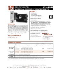
Appendix B – Communications Connector Pin Outs<br />
RS-232 Communication Port<br />
The RS-232 communication port is configured in a 9-pin “D” male connector with the following<br />
pin out:<br />
1. N/C<br />
2. 232 RD (Violet)<br />
3. 232 TD (Yellow)<br />
4. N/C<br />
5. 232 GND (Grey)<br />
6. N/C<br />
7. 232 RTS (Orange)<br />
8. 232 CTS (Brown)<br />
9. N/C<br />
RS-485 Communication Port<br />
The RS-485 communication port is configured in a 25-pin “D” female connector with the<br />
following pin out:<br />
1. N/C 10. N/C 19. N/C<br />
2. -485 (Blue) 11. N/C 20. N/C<br />
3. -485 (Blue) 12. N/C 21. N/C<br />
4. N/C 13. N/C 22. N/C<br />
5. N/C 14. +485 (White) 23. N/C<br />
6. N/C 15. N/C 24. N/C<br />
7. GND 16. +485 (White) 25. GND 485 Drain<br />
8. N/C 17. N/C<br />
9. N/C 18. N/C<br />
<strong>SmartSensor</strong> 125 User <strong>Guide</strong> – <strong>Wavetronix</strong> LLC 4/26/07 31
Appendix C – Old Cable Connector Information<br />
The previously used <strong>SmartSensor</strong> cable is comprised of six twisted pairs of wire. Each pair<br />
consists of a black and a red wire, accompanied by a drain wire and surrounded by a shield. A<br />
numeric label (1 through 6) identifies each pair of black and red wires. The following table<br />
details the pin out of the cable and the appropriate connection inside the cabinet for each wire<br />
(see Table 3):<br />
<strong>SmartSensor</strong><br />
Cable<br />
Description<br />
Cabinet Connection<br />
Black 1<br />
-DC<br />
Negative terminal of 10-30 VDC power supply<br />
which should also be connected to Earth Ground<br />
Red 1 +DC Positive terminal of 10-30 VDC power supply<br />
Drain of Pair 1 GND Earth Ground<br />
Black 2<br />
-DC<br />
Negative terminal of 10-30 VDC power supply<br />
which should also be connected to Earth Ground<br />
Red 2 +DC Positive terminal of 10-30 VDC power supply<br />
Drain of Pair 2 GND Earth Ground<br />
Black 3 -485<br />
Negative RS-485 of a 2-wire RS-485 bus (or pins 2<br />
and 3 of DB25 connector to connect SeaLink 485 or<br />
USB to 485 connector)<br />
Red 3 +485<br />
Positive RS-485 of a 2-wire RS-485 bus or pins 14<br />
and 16 of DB25 connector<br />
Drain of Pair 3 485 GND Earth Ground or pin 7 of DB25 connector<br />
Red 4<br />
232 (TD) output<br />
from sensor<br />
Pin 3 of standard RS-232 DB9 connector<br />
Black 4<br />
232 (RD) input to<br />
sensor<br />
Pin 2 of standard RS-232 DB9 connector if sensor<br />
connector is wired as a DTE device<br />
Drain of Pair 4 232 GND Earth Ground<br />
Pair 5<br />
Reserved for<br />
future use<br />
Leave unconnected<br />
Pair 6<br />
CTS/RTS Flow<br />
for 232<br />
Contact <strong>Wavetronix</strong> for connection information<br />
Table 3 – Cabinet Connection<br />
<strong>SmartSensor</strong> 125 User <strong>Guide</strong> – <strong>Wavetronix</strong> LLC 4/26/07 32
The table below shows the individual wiring of both the new and old <strong>SmartSensor</strong> cables and<br />
how they correspond (see Table 4).<br />
Color-Coded<br />
Cable Bundle<br />
Color-Coded<br />
Cable Wires<br />
Belden 9331 (Old Cable)<br />
Wires<br />
Red Red 1, Red 2<br />
Power Black Black 1, Black 2<br />
Drain<br />
None<br />
White Red 3<br />
RS-485 Blue Black 3<br />
Drain Drain 3<br />
Yellow Red 4<br />
Violet Black 4<br />
RS-232<br />
Orange Black 6<br />
Brown Red 6<br />
Grey Drain 4<br />
Drain Drain 4<br />
None None<br />
Red 5, Black 5, Drain 5,<br />
Drain 6<br />
Table 4 – Belden 9331 (Old Cable) Conversions<br />
<strong>SmartSensor</strong> 125 User <strong>Guide</strong> – <strong>Wavetronix</strong> LLC 4/26/07 33
Appendix C-1 – Click! 200/204 Wiring<br />
Use the illustration below if you are using the old <strong>SmartSensor</strong> cable (see Figure 32):<br />
Figure 32 - Click! 200 Wiring (Old)<br />
Figure 32 above shows the protected side of the Click! 200. The unprotected side of the Click!<br />
200 contains the same screw terminal connections, but in the opposite order.<br />
<strong>SmartSensor</strong> 125 User <strong>Guide</strong> – <strong>Wavetronix</strong> LLC 4/26/07 34
Appendix C-2 – <strong>SmartSensor</strong> Cable Pin Socket Assignments<br />
Figure 33 below illustrates the previously used <strong>SmartSensor</strong> cable’s 25-pin socket assignment.<br />
The codes listed in the diagram are to be used to solder wires into the back of the plug where the<br />
letters represent the individual solder cups.<br />
Figure 33 – Old <strong>SmartSensor</strong> SS105 Plug Connector Socket Assignment as seen from the solder cup side of<br />
the connector.<br />
<strong>SmartSensor</strong> 125 User <strong>Guide</strong> – <strong>Wavetronix</strong> LLC 4/26/07 35
Appendix C-3 – PC and Modem Connections<br />
Communication between the <strong>SmartSensor</strong> and PC can be established using the RS-232 DTE<br />
specifications, along with the use of a null modem cable and the standard 9-pin “D” male<br />
connector. Please use the following guidelines for connecting the <strong>SmartSensor</strong> cable to the serial<br />
connection on a PC or modem when not using a Click! 200.<br />
NOTE: The RS-232 pin outs remain the same on the <strong>SmartSensor</strong> cable regardless of<br />
connecting to a PC or a modem. If connecting to a PC, a null modem cable is required<br />
(see Figure 34). If connecting to a modem or other DCE device, then a straightthrough<br />
serial cable is used (see Figure 35).<br />
Figure 34 – Connecting a PC to the <strong>SmartSensor</strong> <strong>HD</strong><br />
<strong>SmartSensor</strong> RS-232 Connections<br />
SMARTSENSOR CABLE<br />
DB9 SERIAL CONNECTOR<br />
Red 4 (OUT FROM SENSOR)<br />
Pin 3 (TD)<br />
Black 4 (IN TO SENSOR)<br />
Pin 2 (RD)<br />
Drain 4 Pin 5<br />
Table 5 – RS-232 Connections (Old Cable)<br />
<strong>SmartSensor</strong> 125 User <strong>Guide</strong> – <strong>Wavetronix</strong> LLC 4/26/07 36
Figure 35 - Connecting a Modem to the <strong>SmartSensor</strong><br />
<strong>SmartSensor</strong> 125 User <strong>Guide</strong> – <strong>Wavetronix</strong> LLC 4/26/07 37
Appendix D – Cable Lengths<br />
The following recommendations allow the user to provide reliable power to the <strong>SmartSensor</strong>.<br />
The <strong>SmartSensor</strong> cable’s red and black wires provide a 20 AWG wire pair. The other pairs on<br />
the <strong>SmartSensor</strong> cable are 22 AWG and are normally used for communication.<br />
Cable<br />
Power<br />
Gauge Pairs 24 V 12 V<br />
<strong>SmartSensor</strong> Cable<br />
Old <strong>SmartSensor</strong> Cable<br />
20 AWG<br />
22 AWG<br />
1-Pair<br />
1st Pair<br />
600 ft<br />
400 ft<br />
110 ft<br />
75 ft<br />
Additional 22 AWG<br />
Additional 22 AWG<br />
Each Pair<br />
Each Pair<br />
Add 400 ft<br />
Add 400 ft<br />
Add 75 ft<br />
Add 75 ft<br />
14 AWG 1-Pair 2500 ft 450 ft<br />
12 AWG 1-Pair 3900 ft 700 ft<br />
Alternate Power Cables 10 AWG 1-Pair 6000 ft 1050 ft<br />
8 AWG 1-Pair 9900 ft 1750 ft<br />
6 AWG 1-Pair 14,000 ft 2500 ft<br />
Table 6 - Maximum Cable Length for Power (ft)<br />
If the cable length is longer than 600 feet when operating at 24 V, it is possible to increase the<br />
maximum cable length by wiring a pair of lines normally used for RS-232 communications with<br />
the red and black wires.<br />
If the cable length is 200 feet or greater you cannot reliably use RS-232 communications. To<br />
add 400 feet and achieve a maximum cable length of 1000 feet, connect the orange wire<br />
(normally RTS) to the red wire and the brown wire (normally CTS) to the black wire.<br />
If your cable run is longer than 1000 feet, it is possible to sacrifice additional communication<br />
pairs to increase the maximum cable length for power. However, you may desire to<br />
communicate to the sensor over two independent channels, in which case you will need to<br />
consider an alternate cable for power. The AWG for wire pairs that achieve a 2000 ft maximum<br />
cable length or greater at 12 and 24 V are listed in Table 8 (see the <strong>SmartSensor</strong> bid specification<br />
document for more information about cable requirements).<br />
To achieve reliable wired communications, the selected baud rate must be compatible with the<br />
length of the cable run. The table below shows the cable length recommendations for wired<br />
communications (see Table 7):<br />
Baud Rate (Kbps)<br />
115.2 57.6 38.4 19.2 9.6<br />
RS-485 300 ft 600 ft 800 ft 1000 ft 2000 ft<br />
RS-232 40 ft 60 ft 100 ft 140 ft 200 ft<br />
Table 7 - Maximum Cable Length for Wired Communications (ft)<br />
<strong>SmartSensor</strong> 125 User <strong>Guide</strong> – <strong>Wavetronix</strong> LLC 4/26/07 38
To provide two independent communication channels with a homerun cable length over 200 ft,<br />
convert the RS-232 data into RS-485 using a Click! 304 in a pole-mount cabinet mounted next to<br />
the sensor. In this case, the homerun connection establishes one RS-485 channel over the normal<br />
white/blue wire pair and another RS-485 channel over the yellow/violet wire pair. An additional<br />
Click! 304 is needed to convert the data sent over the yellow/violet wire pair back to RS-232<br />
before connecting to surge protection.<br />
<strong>SmartSensor</strong> 125 User <strong>Guide</strong> – <strong>Wavetronix</strong> LLC 4/26/07 39