MEMCAPACITOR MODELING IN MICRO-CAP - ResearchGate
MEMCAPACITOR MODELING IN MICRO-CAP - ResearchGate
MEMCAPACITOR MODELING IN MICRO-CAP - ResearchGate

You also want an ePaper? Increase the reach of your titles
YUMPU automatically turns print PDFs into web optimized ePapers that Google loves.
<strong>MEM<strong>CAP</strong>ACITOR</strong> <strong>MODEL<strong>IN</strong>G</strong> <strong>IN</strong> <strong>MICRO</strong>-<strong>CAP</strong><br />
Dalibor Biolek 1)2) , Zdeněk Biolek 3) , and Viera Biolková 2)<br />
1)<br />
University of Defence Brno, Kounicova 65, Brno, Czech Republic<br />
2)<br />
Brno University of Technology, Antonínská 1, Brno, Czech Republic<br />
3)<br />
SŠIEŘ, Školní 1610, Rožnov p.R., Czech Republic<br />
fax: +420 973443773, e-mail: dalibor.biolek@unob.cz, http://user.unob.cz/biolek<br />
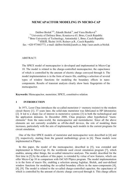
ABSTRACT:<br />
The SPICE model of memcapacitor is developed and implemented in Micro-Cap<br />
10. The model is related to the charge-controlled memcapacitor, the capacitance<br />
of which is controlled by the amount of electric charge conveyed through it. The<br />
model implementation is in the form of macro file, enabling a selection of several<br />
types of window functions for modeling the boundary effects in nanocomponents.<br />
Results of transient analysis clearly show basic fingerprints of the<br />
memcapacitor.<br />
Keywords: Memcapacitor, memristor, SPICE, constitutive relation<br />
1 <strong>IN</strong>TRODUCTION<br />
In 1971, Leon Chua introduces the so-called memristor (= memory resistor) to the modern<br />
circuit theory [1]. 37 years later, the solid-state memristor was fabricated in HP laboratories<br />
[2]. It led to a sharp rise of interest in memristive systems [3] in both the technological and<br />
the application domains. In December 2008, Chua proposes other hypothetical “memelements”<br />
from the nano-world, the memcapacitor and meminductor. Since all the above<br />
elements are not currently available as off-the-shelf devices, the role of modeling them<br />
increases, particularly with the aim of implementing such models in the current programs for<br />
circuit simulation.<br />
One of the first SPICE models of memristor and memcapacitor were described in [4] and<br />
[5], respectively, starting from the general methodology given in [6]. These models were<br />
implemented in PSpice.<br />
In this paper, the model of the memcapacitor, described in [5], was extended and<br />
implemented in Micro-Cap 10, the worldwide used circuit simulation program [7], which<br />
enables, among other things, the so-called interactive analyses. The model, described for the<br />
first time in [5] by the authors of this paper, is extended by virtue of new features, which can<br />
offer Micro-Cap 10 in comparison with OrCAD PSpice program. The model implementation<br />
is in the form of macro file, enabling a selection among Joglekar, Biolek, and user-defined<br />
window functions for modeling the so-called boundary effects in the nano-components [4],<br />
[8], [9]. The model is related to the so-called charge-controlled capacitor, the capacitance of<br />
which is controlled by the amount of electric charge conveyed through it. This charge affects
the width of the dielectric. The results of transient analysis clearly show three basic<br />
fingerprints of the memcapacitor: unambiguous constitution relation [5], the hysteretic effect<br />
in the Coulomb-Volt characteristic, and the identical time instants when the voltage and<br />
charge waveforms cross zero levels.<br />
2 SPICE-ORIENTED <strong>MEM<strong>CAP</strong>ACITOR</strong> MODEL<br />
The charge-controlled memcapacitor is characterized by the following port equation (PE)<br />
and first-order state equation (SE) [5]:<br />
PE:<br />
d<br />
v = DM ( x,<br />
q,<br />
t)<br />
q , SE: x& = x = f<br />
q<br />
( x,<br />
q,<br />
t)<br />
, (1)<br />
dt<br />
where v and q are electric voltage and charge of the memcapacitor, D M = 1/C M is an inverse<br />
memcapacitance and C M is a memcapacitance, and x is an internal state variable of the<br />
memcapacitor. Charge-controlled memcapacitor is a special type of time-varying capacitor,<br />
(inverse) capacitance of which depends on the quantities indicated in Eq. (1).<br />
The well-known relation between the voltage and current of the time-varying capacitor<br />
t<br />
v(<br />
t)<br />
= DM<br />
( t)[<br />
CM<br />
(0) v(0)<br />
+ ∫ i(<br />
ξ ) dξ<br />
] = [ CM<br />
(0) v(0)<br />
+ ∫ i(<br />
ξ ) dξ<br />
]/ CM<br />
( t)<br />
, (2)<br />
0<br />
where v(0) and C M (0) are initial voltage and capacitance of the memcapacitor at time t = 0,<br />
can be a starting point of the SPICE model, schematically described in Fig. 1.<br />
t<br />
0<br />
∫<br />
q<br />
v<br />
i<br />
Int<br />
q<br />
v( )<br />
q<br />
v(0)<br />
q<br />
q<br />
.<br />
x<br />
x<br />
DM( ) f ( ) ∫<br />
q<br />
Int x<br />
x<br />
Fig. 1: Block diagram of the SPICE model of charge-controlled memcapacitor<br />
Equation (2) is modeled via a voltage source which is controlled from the block labeled as<br />
“v( )”. The input data of this block are time-domain integral of current, i.e. charge q, the initial<br />
voltage v(0), and the inverse memcapacitance as a function of charge and state x. The state<br />
variable is computed from the differential SE (1) which is modeled using the block of<br />
nonlinear function f q and the integrator Int x .<br />
The above general model can be used for modeling charge-controlled memcapacitors of<br />
arbitrary nature. The contents of the blocks D M ( ) and f q ( ) depend on physical principle of<br />
concrete memcapacitor.<br />
The following Section describes a sample example of memcapacitor which is included in<br />
the Micro-Cap 10 release [7].
3 <strong>MEM<strong>CAP</strong>ACITOR</strong> MODEL <strong>IN</strong> <strong>MICRO</strong>-<strong>CAP</strong> 10<br />
The contents of the Micro-Cap macro file of the memcapacitor is shown in Fig. 2. The<br />
schematic of a capacitor with moving right-side plate is accompanied by the basic notes how<br />
the capacitance depends on the position of this plate. The state variable x is derived from this<br />
position such that it can vary within the interval (0, 1). The state equation from [5] is<br />
considered. It contains the window function for modeling boundary conditions [4-6], [8-9].<br />
<strong>MEM<strong>CAP</strong>ACITOR</strong> MACRO<br />
Cmax<br />
C(t) Cmin x = (l-lmin)/(lmax-lmin) .. state variable from the interval (0,1)<br />
C(t) .. capacitance of memcapacitor<br />
D(t) = 1/C(t) = 1/Cmax+ (1/Cmin-1/Cmax)*x(t)<br />
.. inverse capacitance of memcapacitor<br />
lmin<br />
l<br />
lmax<br />
dx/dt = k*q(t)*window(x)<br />
.. time derivative of the state depends on the charge<br />
(charge-controlled memcapacitor)<br />
window(x) ..see the text folder for details<br />
.PARAMETERS(Cmin=10n,Cmax=10u,Cinit=100n,k=10meg,p=1,ICO=0,window_type=2)<br />
Plus<br />
Minus<br />
{DM*(v(charge)+ICO*Cinit)}<br />
Eb<br />
Gq<br />
i(Eb)<br />
charge<br />
1G<br />
Cq 1 Rq<br />
window*v(charge)*k<br />
x<br />
Gx<br />
Cx<br />
1 IC=x0<br />
1G<br />
Rshunt<br />
SDT(V(Plus,Minus))<br />
flux<br />
SDT(v(charge))<br />
intcharge<br />
Eflux<br />
Eintcharge<br />
*The two lines below define initial state of the memcapacitor<br />
*and the controlling law of its capacitance.<br />
*These lines should be modified for another physical implementation of memcapacitor.<br />
.define x0 ((1/Cinit-1/Cmax)/(1/Cmin-1/Cmax))<br />
.define DM (1/Cmax+(1/Cmin-1/Cmax)*Xlimited)<br />
*Window functions<br />
.IF window_type=0<br />
.define window sqrt(V(x)-(V(x))^2);user-defined window<br />
;replace this sample expression by your model<br />
.ELIF window_type=1<br />
.define window (1-(2*Xlimited-1)^(2*p));Joglekar window<br />
.ELIF window_type=2<br />
.define window (1-(Xlimited-(1-sgn(V(plus,minus)))/2)^(2*p));Biolek window<br />
.ENDIF<br />
.define Xlimited (if(V(x)1,1,V(x))));V(x) limiter<br />
Fig. 2: Complete memcapacitor macro<br />
The current source G q together with the one-farad capacitor C q and shunting resistor R q for<br />
providing DC path to ground model the integrator Int q from Fig. 1 for transforming the<br />
memcapacitor current to charge. The charge value is available in the form of the voltage at<br />
node “charge”. The current source G x together with C x and R shunt model the integrator Int x for<br />
evaluating the state equation (1). The auxiliary voltage sources Eflux and Eintcharge serve for
computing the time-domain integrals of voltage (i.e. flux) and charge (i.e. TIQ, time-domain<br />
integral of charge). These quantities, which are important constitutive variables of the<br />
memcapacitor, can be then easily visualized in transient analysis results.<br />
4 EXAMPLE OF ANALYSIS<br />
Results of transient analysis of memcapacitor driven by pulse-waveform voltage source<br />
with the internal resistance of 1 mΩ are presented in Fig. 3.<br />
80n<br />
60n<br />
40n<br />
1.0<br />
100n<br />
20n<br />
0n<br />
1.2<br />
0.0 0.2 0.4 0.6 0.8 1.0<br />
V(XJ.IntCharge) (V)<br />
V(XJ.FLUX) (V)<br />
(a)<br />
0.5<br />
50n<br />
0.6<br />
0.0<br />
0n<br />
0.0<br />
-0.5<br />
-1.0<br />
-50n<br />
-100n<br />
200n<br />
-0.6<br />
-1.2<br />
1.0<br />
40 44 48 52 56 60<br />
V(memJ) (V) V(XJ.charge) (V) V(XJ.flux) (V)<br />
time (Secs)<br />
(b)<br />
170n<br />
0.8<br />
140n<br />
0.6<br />
110n<br />
0.4<br />
80n<br />
50n<br />
0.2<br />
0.0<br />
1.5<br />
40 44 48 52 56 60<br />
V(XJ.X) (V) capacityJ<br />
time (Secs)<br />
(c)<br />
1.0<br />
0.5<br />
0.0<br />
-0.5<br />
-1.0<br />
-1.5<br />
-120n -90n -60n -30n 0n 30n 60n 90n 120n<br />
v(in) (V)<br />
V(XJ.charge) (V)<br />
(d)<br />
Fig. 3: Transient analysis of memcapacitor excited by pulse voltage source: (a) constitutive relation, (b)<br />
waveforms of input voltage V(memJ), charge V(XJ.charge), and flux V(XJ.flux), (c) time evolution of state<br />
variable V(XJ.X) and memcapacitance, (d) Volt-Coulomb hysteretic characteristic
The memcapacitor has the following parameters: C min = 50 nF, C max = 200 nF,<br />
C init = 100 nF, ICO = 0, p = 10, Joglekar window. The 900 ms width and 10 ms rise/fall time<br />
bipolar ±1V pulses in Fig. 3 (b) cause the pulse waveforms of the charge which modifies the<br />
position of the plate of the memcapacitor. The corresponding variation of the memcapacity is<br />
shown in Fig. 3 (c). The following Fig. 3 (d) depicts the Volt-Coulomb characteristic with<br />
typical pinched hysteresis loop.<br />
5 CONCLUSIONS<br />
The memcapacitor model in Fig. 1 is quite general. Together with Eqs. (1) and (2), it can<br />
be used for modeling memcapacitor, the capacitance of which is controlled via various<br />
physical mechanisms.<br />
6 ACKNOWLEDGMENTS<br />
Research described in the paper was supported by the Czech Science Foundation under<br />
grant No. P102/10/1614, and by the research programmes of BUT Nos.<br />
MSM0021630503/513 and UD Brno No. MO FVT0000403, Czech Republic.<br />
7 REFERENCES<br />
[1] Chua, L.O.; Memristor–the missing circuit element. IEEE Trans. Circuit Theory, CT-<br />
18 (1971), No. 5, pp. 507–519.<br />
[2] Strukov, D.B., Snider, G.S., Stewart, D.R., Williams, R.S.; The missing memristor<br />
found. Nature, 453 (2008), pp. 80 – 83.<br />
[3] Chua, L.O., Kang, S.M.; Memristive devices and systems. Proceedings of the IEEE, 64<br />
(1976), No. 2, pp. 209-223.<br />
[4] Biolek, Z., Biolek, D., Biolková, V.; SPICE model of memristor with nonlinear dopant<br />
drift. Radioengineering, 18 (2009), No. 2, pp. 210–214.<br />
[5] Biolek, D., Biolek, Z., Biolková, V.; SPICE modelling of memcapacitor. Electronics<br />
Letters, 46 (2010), No. 7, pp. 520-522.<br />
[6] Biolek, D., Biolek, Z., Biolková, V.; SPICE Modeling of Memristive, Memcapacitative<br />
and Meminductive Systems. Proceedings of ECCTD '09, Antalya, Turkey, 2009, pp.<br />
249-252.<br />
[7] Micro-Cap homepage: www.spectrum-software.com<br />
[8] Joglekar, Y.N., Wolf, S.J.; The elusive memristor: properties of basic electrical<br />
circuits. Eur.J.Phys., 30 (2009), pp. 661-675.<br />
[9] Kavehei, O., Iqbal, A., Kim, Y.S., Eshraghian, K., Al-Sarawi, S.F., Abbot, D.; The<br />
fourth element: characteristics, modelling, and electromagnetic theory of the<br />
memristor. arXiv:1002.3210v1 [cond-mat.mes-hall] 17 Feb 2010.