user's manual - Ana-Digi Systems
user's manual - Ana-Digi Systems
user's manual - Ana-Digi Systems

You also want an ePaper? Increase the reach of your titles
YUMPU automatically turns print PDFs into web optimized ePapers that Google loves.
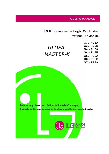
USER’S MANUAL<br />
LG Programmable Logic Controller<br />
Profibus-DP Module<br />
GLOFA<br />
MASTER-K<br />
G3L-PUEA<br />
G3L-PUEB<br />
G4L-PUEA<br />
G4L-PUEB<br />
G6L-PUEA<br />
G6L-PUEB<br />
G7L-PBEA<br />
Before using, please read ‘ Notices for the safety ’thoroughly.<br />
Please keep this user’s <strong>manual</strong> in the place where the user can find easily.
Notices for the Safety<br />
‘Notices for the Safety’ should be complied by the user to use the<br />
product safely and correctly to prevent the occurrence of any<br />
accident or danger.<br />
‘Notices for the Safety’ is divided by “Danger”, ”Warning” and ”Caution”<br />
and each meaning is as follows :<br />
Danger<br />
In case of violating the instructions, it may cause the<br />
significant injury or death immediately.<br />
Warning<br />
In case of violating the instructions, it may cause<br />
the significant injury or death.<br />
Caution<br />
In case of violating the instructions, it may cause<br />
the slight injury or product damage.<br />
■ The meaning of symbols used in the product and user’s <strong>manual</strong> is as follows :<br />
This symbol is to take care for the items or operation that may occur the<br />
danger.<br />
When you find this symbol, you should read the instructions carefully to<br />
avoid the danger occurrence.<br />
This symbol is to take care as the electric shock may occur under<br />
the specific condition.
■ Notices in Design<br />
Caution<br />
I/O Signal/Communication cables shall be designed apart at least 100mm from high voltage<br />
cable or power cable to avoid the influence caused by the noise or the change of magnetic filed.<br />
It may cause the malfunction by the noise.<br />
In case that installation environment has lots of vibration, cares should be taken not to apply the<br />
vibration to the product directly.<br />
The inflow of metal particle is not permitted as it may cause the malfunction of the product.<br />
■ Notices in Installation<br />
Caution<br />
PLC should be used in the environment condition described in the general standard.<br />
If used out of general standard, it may cause the electric shock, fire, malfunction, damage of<br />
product or furious flames etc.<br />
Make sure that the module is fixed correctly.<br />
If not installed the module correctly, it may cause the malfunction, failure or falling.<br />
■ Notices in Wiring<br />
Caution<br />
For the grounding of FG terminal, you should use the 3 rd class grounding only for PLC.<br />
If not grounding, it may cause the malfunction.<br />
The wiring in PLC should be connected after checking the rating voltage of the product and<br />
terminal layout.<br />
If connected to the different power from the rating or wrong wiring, it may cause the fire or<br />
failure.<br />
In case of wiring, the screw of terminal should be tightened by standard torque.<br />
If the screw of terminal is loosened, it may cause the cutoff or malfunction.<br />
Cares should be taken to avoid the inflow of foreign materials such as wiring dregs inside the<br />
module.
■ Notices in Startup and Maintenance<br />
Warning<br />
Do not touch the terminal in the state that the power is applied. It may cause the malfunction or<br />
electric shock.<br />
Caution<br />
Do not remove PCB from the module case or remodel the module. It may cause the failure,<br />
malfunction, damage of the product or fire. The installation and removal of the module should<br />
be done after POWER OFF.<br />
The change of battery should be done in the state of POWER ON.<br />
In case of changing in the state ‘OFF’, the program may be damaged.<br />
■ Notices in Disposal<br />
Caution<br />
When the product is disposed, this should be treated as industry waste.
REVISION HISTORY<br />
Issue Date Manual No. Revised Content<br />
’04.4 10310000334 First edition issued.<br />
※User’s Manual no. is marked on the right bottom side of the back cover.
Table of Contents<br />
CHAPTER 1 OVERVIEW•••••••••••••••••••••••••••••••••••••••••••••••••••••••••••••••••••••••1-1 ~ 1-2<br />
1.1 Notices in using•••••••••••••••••••••••••••••••••••••••••••••••••••••••••••••••••••••••••••••••• 1-2<br />
CHAPTER 2 TERMINOLOGY•••••••••••••••••••••••••••••••••••••••••••••••••••••••••••••••••2-1 ~ 2-2<br />
CHAPTER 3 GENERAL SPECIFICATION••••••••••••••••••••••••••••••••••••••••••••••••3-1 ~ 3-2<br />
3.1 General Specification•••••••••••••••••••••••••••••••••••••••••••••••••••••••••••••••••••••••••• 3-1<br />
3.2 Pnet Telecommunication module structure•••••••••••••••••••••••••••••••••••••••••••• 3-2<br />
CHAPTER 4 PERFORMANCE SPECIFICATION•••••••••••••••••••••••••••••••••••••••••••••••4-1<br />
4.1 Telecommunication Specification•••••••••••••••••••••••••••••••••••••••••••••••••••••••••• 4-1<br />
CHAPTER 5 SYSTEM CONFIGURATION•••••••••••••••••••••••••••••••••••••••••••••••••••••••••5-1<br />
5.1 Profibus-DP System •••••••••••••••••••••••••••••••••••••••••••••••••••••••••••••••••••••••••• 5-1<br />
CHAPTER 6 TELECOMMUNICATION CONFIGURATION•••••••••••••••••••••••6-1 ~ 6-61<br />
6.1 High speed link•••••••••••••••••••••••••••••••••••••••••••••••••••••••••••••••••••••••••••••••• 6-1<br />
6.1.1 Overview•••••••••••••••••••••••••••••••••••••••••••••••••••••••••••••••••••••••••••••••• 6-1<br />
6.1.2 Operation procedure by high speed link••••••••••••••••••••••••••••• 6-2<br />
6.1.3 SyCon •••••••••••••••••••••••••••••••••••••••••••••••••••••••••••••••••••••••••••••••••• 6-2<br />
6.1.4 High speed link parameter setting in GMWIN••••••••••••••••••••••••• 6-11<br />
6.1.5 High speed link operation in GMWIN •••••••••••••••••••••••••••••••••••• 6-16<br />
6.1.6 High speed link information in GMWIN ••••••••••••••••••••••••••••••••• 6-17<br />
6.1.7 High speed link parameter setting in KGLWIN••••••••••••••••••••••• 6-22<br />
6.1.8 Speed calculation of high speed link•••••••••••••••••••••••••••••••••• 6-25<br />
6.2 Example Program ••••••••••••••••••••••••••••••••••••••••••••••••••••••••••••••••••••••••••• 6-28<br />
6.2.1 Pnet master slave telecommunication in GMWIN•••••••••••••••••••••• 6-28<br />
6.2.2 Smart I/O Pnet master slave telecommunication in GMWIN•••••• 6-38<br />
6.2.3 Pnet master slave telecommunication in KGLWIN••••••••••••••••••••• 6-46<br />
6.2.4 Smart I/O Pnet master slave telecommunication in KGLWIN••••••• 6-55
CHAPTER 7 DIAGNOSIS FUNCTION•••••••••••••••••••••••••••••••••••••••••••••••••••••7-1 ~ 7-2<br />
7.1 LED ••••••••••••••••••••••••••••••••••••••••••••••••••••••••••••••••••••••••••••••••••••••••••••••••• 7-1<br />
CHAPTER 8 INSTALLATION & STARTUP•••••••••••••••••••••••••••••••••••••••••••••••8-1 ~ 8-7<br />
8.1 Installation •••••••••••••••••••••••••••••••••••••••••••••••••••••••••••••••••••••••••••••••••••••••• 8-1<br />
8.1.1 Notices in installation••••••••••••••••••••••••••••••••••••••••••••••••••••••••••••••• 8-1<br />
8.1.2 Cable installation••••••••••••••••••••••••••••••••••••••••••••••••••••••••••••••••••••• 8-2<br />
8.2 Startup•••••••••••••••••••••••••••••••••••••••••••••••••••••••••••••••••••••••••••••••••••••••••••••• 8-4<br />
8.2.1 Notices in system configuration••••••••••••••••••••••••••••••••••••••••••••••••• 8-4<br />
8.2.2 Checklist before startup••••••••••••••••••••••••••••••••••••••••••••••••••••••••••• 8-4<br />
8.3 Maintenance & Checking•••••••••••••••••••••••••••••••••••••••••••••••••••••••••••••••••••• 8-6<br />
8.3.1 Daily checking•••••••••••••••••••••••••••••••••••••••••••••••••••••••••••••••••••••••• 8-6<br />
8.3.2 Regular checking•••••••••••••••••••••••••••••••••••••••••••••••••••••••••••••••••••• 8-7<br />
CHAPTER 9 TROUBLE SHOOTING•••••••••••••••••••••••••••••••••••••••••••••••••••••••9-1 ~ 9-9<br />
9.1 Basic procedure of Trouble shooting••••••••••••••••••••••••••••••••••••••••••••••••••••• 9-1<br />
9.1.1 Hardware Error••••••••••••••••••••••••••••••••••••••••••••••••••••••••••••••••••••••• 9-2<br />
9.1.2 Interface Error••••••••••••••••••••••••••••••••••••••••••••••••••••••••••••••••••••••••• 9-3<br />
9.1.3 Network Error••••••••••••••••••••••••••••••••••••••••••••••••••••••••••••••••••••••••• 9-4<br />
9.1.4 CPU and Interface error during operation••••••••••••••••••••••••••••••••••• 9-5<br />
9.1.5 High speed parameter error ••••••••••••••••••••••••••••••••••••••••••••••••••• 9-6<br />
9.1.6 High speed link operation error •••••••••••••••••••••••••••••••••••••••••••••••• 9-7<br />
9.1.7 GMWIN/KGLWIN communication time out•••••••••••••••••••••••••••••••••• 9-8<br />
9.1.8 GMWIN/KGLWIN internal communication error••••••••••••••••••••••••••• 9-9<br />
CHAPTER 10 EXTERNAL DIMENSION••••••••••••••••••••••••••••••••••••••••••••••••••••••••••10-1
CHAPTER 1 OVERVIEW<br />
CHAPTER 1 OVERVIEW<br />
This user’s <strong>manual</strong> describes GLOFA-GM/MASTER-K Profibus (hereinafter referred as‘Pnet’) which is<br />
Profibus module among network modules of PLC system technically in detail.<br />
Please refer to the following user’s <strong>manual</strong>s to prepare the program.<br />
• GLOFA-GM PLC Command collection<br />
• GLOFA-GM PLC GMWIN User’s <strong>manual</strong><br />
• MASTER-K PLC Command collection<br />
• MASTER-K PLC KGLWIN User’s <strong>manual</strong><br />
For Pnet system configuration, cares should be taken to the followings<br />
· GLOFA-GM PLC GMWIN Program Tool: more than Ver 3.4<br />
· GLOFA GM1/2 CPU : more than Ver 3.2<br />
· GLOFA GM3 CPU : more than Ver 2.4<br />
· GLOFA GM4 CPUA/CPUB/CPUC : Ver 2.5/ Ver 2.5/ more than Ver 2.0<br />
· GLOFA GM6 CPUA/CPUB/CPUC : Ver 1.8/ Ver 1.8/ more than Ver 1.8<br />
· GLOFA GM7 CPU : more than Ver 1.5<br />
· MASTER-K PLC KGLWIN Program Tool: more than Ver 3.2<br />
· MASTER-K 1000S CPU : more than Ver 3.0<br />
· MASTER-K 300S CPU : more than Ver 3.0<br />
· MASTER-K 200S CPU : more than Ver 2.5<br />
· MASTER-K 120S CPU : more than Ver 1.1<br />
· MASTER-K 80S CPU : more than Ver 1.5<br />
The features of GLOFA Pnet are as follows :<br />
• International standard : EN 50170<br />
• Device type : Profibus DP Master/ Slave<br />
• Auto Baud Rate Detect : support<br />
• Sync mode : support<br />
• Freeze mode : support<br />
• Max. input data : 64 byte/Slave<br />
• Max. output data : 64 byte/Slave<br />
• Max. data size : 128 byte/Slave, (1kbytes or 7kbytes)/Master<br />
• Communication speed : 9.6K, 19.2K, 93.75K, 187.5K, 500K, 1.5M, 3M, 6M, 12M<br />
• Modular Station : support<br />
1-1
CHAPTER 1 OVERVIEW<br />
1.1 Notices in using<br />
When you install this device, cares should be taken to the following items for the reliability and safety of<br />
system.<br />
Items Classification Description<br />
Temperature Condition • When installing this device, the use temperature should be 0 ~<br />
55℃ for the part elements.<br />
• Direct exposure to the direct ray of light is not allowed.<br />
Action • If the temperature is high, the fan or air conditioner is required<br />
while you should maintain the proper temperature if the<br />
temperature is low.<br />
Dew<br />
condensation<br />
Condition • No dew by a sudden change of temperature.<br />
• Install inside the control panel available for water-proof or<br />
vibration resistance.<br />
Action • The temperature change due to frequent power On/Off may<br />
cause the dew condensation. In this case, keep the power ON<br />
even in the night time.<br />
Impact Condition • Install in the place free from impact or vibration.<br />
Action • In case of serious impact or vibration, use the vibration-resistant<br />
rubber to prevent from applying the impact or vibration to the<br />
device.<br />
Gas Condition • Install in the place having no corrosive gas.<br />
Action • In case of inflow of the corrosive gas from outside, it is required<br />
to take measures for air conditioning of the control panel where<br />
installed the device.<br />
EMC Condition • Install in the proper place for the electric magnetic field.<br />
environment Action • Select the correct path of the cables in case of wiring.<br />
• Check if the sheltering of the control panel is done properly.<br />
• For the lighting inside the control panel, use the incandescent<br />
lamp instead fluorescent lamp.<br />
• Power module should be grounded on the standard electric<br />
potential.<br />
1-2
CHAPTER 2 TERMINOLOGY<br />
CHAPTER 2 TERMINOLOGY<br />
Profibus<br />
Profibus is a protocol designated as German standard DIN 19245, developed by Bosch, Siemens,<br />
Klockener-Moeller in Germany and also a network designated as European standard EN50170 together<br />
with WorldFIP, P-NET.<br />
Profibus is used for the real time communication between field equipments in the area of production<br />
automation, processing control, building automation etc. and the product group is divided into Profibus-<br />
FMS (Fieldbus Message Specification), Profibus-DP (Decentralized Periphery), Profibus-PA(Process<br />
Automation).<br />
Profibus-FMS<br />
This is a solution for the general purpose providing the communication function on the cell level. The<br />
services provided include program file to run the field equipment, the function to send the data related to<br />
the program file, the function to control the program remotely through network, and the function to<br />
manage various accidents that may occur while operating the control or automation system.<br />
Profibus-DP<br />
This is a communication system to send the real time data between field equipments within the short<br />
time and replace the existing communication system using an analog signal of 24V and 4-20mA with a<br />
high speed digital communication mode. The examples for application are the communication between<br />
field equipments such as various kinds of sensor or actuator installed in PLC or in the field.<br />
Profibus-PA<br />
This is designed especially for the processing automation and enables to connect the sensor and<br />
actuator by one common bus line with the embedded safety device, and supply the power to the data<br />
communication on bus by using 2-wire technology in accordance with international standard IEC 1158-2.<br />
Sycon<br />
This is a Profibus Network Configuration Tool. When using a master module (G3/4/6L-PUEA/PUEB) of<br />
LGIS, it is required to configure Pnet by using Sycon and download the information to the relevant master<br />
module.<br />
GSD file<br />
This is an electronic device data sheet that includes manufacturer, device name, hardware/ software<br />
sales, support transmitting rate, master related specification (max. number of connectable slave,<br />
upload/download option etc.) and slave related specification (number and type of I/O channels, diagnosis<br />
text specification and module information available with modular device).<br />
EDD (Electronic Device Description)<br />
This describes the registration information of Profibus field device generally and allows to explain the<br />
complicated automation system as well as simple field device (sensor and/or actuator) regardless of<br />
manufacturer. The device description is provided in electronic format made by the manufacturer per<br />
device. EDD file should be read by engineering tool and enables to simplify the Profibus system setting.<br />
This file describes the variables and the function of the device and contains the elements for operation<br />
and visualization.<br />
2-1
CHAPTER 2 TERMINOLOGY<br />
Broadcast Communication<br />
This is to send the message not recognized by Operation Station to all station (Master, Slave).<br />
Multicast Communication<br />
This is to send the not recognized message to the pre-fixed Station group (Master, Slave) by Operation<br />
Station.<br />
2-2
CHAPTER 3 GENERAL SPECIFICATION<br />
CHAPTER 3 GENERAL SPECIFICATION<br />
3.1 General Specification<br />
The General Specification for the communication module of GLOFA series and MASTER-K series is as follows:<br />
No. Items Specification Reference<br />
1 Use Temperature 0 ~ 55 °C<br />
2 Storage Temp. −25°C ~ +70 °C<br />
3 Use humidity 5 ~ 95%RH, no dew<br />
4 Storage humidity 5 ~ 95%RH, no dew<br />
In case of Intermittent vibration -<br />
Frequency Acceleration Amplitude Times<br />
10 ≤ f < 57Hz − 0.075mm<br />
5 Vibration-resistant 57 ≤ f ≤ 150Hz 9.8m/s 2 {1G} −<br />
X, Y, Z<br />
In case of Continuous vibration<br />
10 times<br />
Frequency Acceleration Amplitude<br />
each direction<br />
10 ≤ f < 57Hz − 0.035mm<br />
57 ≤ f ≤ 150Hz 4.9m/s 2 {0.5G} −<br />
6 Impact-proof<br />
7 Noise-resistant<br />
8<br />
Surrounding<br />
environment<br />
• Max. impact acceleration : 147 m/s 2 {15G}<br />
• Application time : 11ms<br />
• Pulse wave type : semi-sine wave pulse (3 times each direction X,Y,Z)<br />
Square wave<br />
impulse noise<br />
Electrostatic<br />
discharge<br />
Radiant<br />
electromagnetic<br />
field noise<br />
Fast transient<br />
/ Bust noise<br />
Classification<br />
No corrosive gas, no dust<br />
9 Use altitude Less than 2,000m<br />
10 Pollution Less than 2<br />
11 Cooling method Natural air-conditioning<br />
± 1,500 V<br />
Voltage : 4kV (Touch discharge)<br />
Power<br />
modul<br />
e<br />
27 ~ 500 MHz, 10 V/m<br />
<strong>Digi</strong>tal I/O<br />
(more than 24V)<br />
<strong>Digi</strong>tal I/O<br />
(less than 24V)<br />
<strong>Ana</strong>log I/O<br />
Communication<br />
interface<br />
Voltage 2kV 1kV 0.25kV<br />
IEC61131-2<br />
IEC61131-2<br />
LGIS internal<br />
test standard<br />
IEC61131-2<br />
IEC1000-4-2<br />
IEC1131-2,<br />
IEC1000-4-3<br />
IEC1131-2<br />
IEC1000-4-4<br />
Table 3.1 General Specification<br />
Note<br />
1) IEC(International Electrotechnical Commission) : International civil community that promotes international cooperation<br />
for standardization of electric/electro technology, publishes international standard and operates suitability assessment<br />
system related to the above.<br />
2) Pollution Degree : An index to indicates the pollution degree of used environment that determines the insulation<br />
performance of the device. For example, pollution degree 2 means the state to occur the pollution of non-electric<br />
conductivity generally, but the state to occur temporary electric conduction according to the formation of dew.<br />
3-1
CHAPTER 3 GENERAL SPECIFICATION<br />
3.2 Pnet I/F Module Configuration<br />
G3L-PUEA<br />
RUN<br />
READY<br />
ERROR<br />
STATUS<br />
LINK-IF<br />
1<br />
G4L-PUEA<br />
RUN<br />
READY<br />
ERROR<br />
STATUS<br />
LINK-IF<br />
1<br />
G6L-PUEA<br />
RUN<br />
READY<br />
ERROR<br />
STATUS LINK<br />
COMM.<br />
CONN.<br />
1<br />
2<br />
G7L-PBEA<br />
PROGRAMMABLE<br />
LOGIC<br />
CONTROLLER<br />
COM RUN<br />
ERROR LINK-IF<br />
5<br />
1<br />
COMM.<br />
CONN.<br />
2<br />
CONFIG.<br />
CONN.<br />
3<br />
2 4<br />
COMM.<br />
CONN.<br />
2<br />
CONFIG.<br />
CONN.<br />
3<br />
CONFIG.<br />
CONN.<br />
3<br />
No. Names Description<br />
1 LED indicator Refer to LED display contents.<br />
2<br />
3<br />
Profibus-DP<br />
connector<br />
Configuration<br />
connector<br />
Connector for Profibus network (D-SUB 9 pin connector, female type)<br />
Connector to download the layout diagram of the prepared Profibus network, by<br />
using configuration tool.(D-SUB 9 pin connector, female type, refer to cable<br />
connection drawing.)<br />
4 Station no. switch Station no. switch of slave module (1~126 stations setting)<br />
5 Extension connector Connector to connect the extension module.<br />
Table 3.2 Module Configurations<br />
*G3L-PUEB, G4L-PUEB, G6L-PUEB are the same configuration.<br />
3-2
CHAPTER 4 PERFORMANCE SPECIFICATION<br />
CHAPTER 4 PERFORMANCE SPECIFICATION<br />
4.1 Communication Specification<br />
Type<br />
Items<br />
G3/4/6L-PUEA G3/4/6L-PUEB G7L-PBEA<br />
Module type Master Slave<br />
Network type<br />
Profibus-DP<br />
Standard<br />
EN50170/DIN19245<br />
Interface<br />
RS-485(electric power)<br />
Transmission mode<br />
Bus mode<br />
Modulation mode<br />
NRZ<br />
MAC Local token ring Poll<br />
Total extension length &<br />
speed<br />
1000m(9.6k~187kbps)<br />
400m(500kbps)<br />
200m(1.5Mbps)<br />
100m(3M~12Mbps)<br />
Max. no. of connection per<br />
network<br />
126 stations<br />
Max. no. of connection per<br />
segment<br />
32 stations<br />
Use cable<br />
Electric : twisted pair cable<br />
Max. communication point 1kbyte 7kbytes 64byte / slave<br />
GMWIN<br />
communication<br />
parameter<br />
(in case of using GM7<br />
Configuration tool only for<br />
Communication parameter<br />
basic module)<br />
GMWIN/KGLWIN high speed link<br />
setting<br />
KGLWIN<br />
parameter<br />
communication<br />
parameter<br />
(in case of using<br />
K80S basic module)<br />
Internal consumption<br />
current (mA)<br />
542/544/505 594/656/682 337<br />
Weight (g) 373/230/135 373/230/135 204<br />
Table 4.1 Communication specifications<br />
4-1
CHAPTER 5 SYSTEM CONFIGURATION<br />
CHAPTER 5 SYSTEM CONFIGURATION<br />
5.1 Profibus-DP System<br />
GMWIN<br />
Sycon<br />
Configuration software<br />
GM3/K1000S<br />
G3L-PUEA/PUEB<br />
GM4/K300S<br />
G4L-PUEA/PUEB<br />
GM6<br />
G6L-PUEA/PUEB<br />
SmartI/O<br />
GPL-D22A/C<br />
GPL-TR2A/A1/C1<br />
GPL-TR2B/C<br />
SmartI/O<br />
GPL-RY2A/C<br />
GPL-D24A/C<br />
GPL-DT4A/A1/B/C/C1<br />
GPL-TR4A/A1/B/C/C1<br />
GM7/K80S,K120S<br />
G7L-PBEA<br />
CNC<br />
LG PLC<br />
SIEMENS PLC<br />
SmartI/O<br />
GM7/K80S,K120S<br />
G7L-PBEA<br />
5-1
CHAPTER 6 COMMUNICATION FUNCTION<br />
CHAPTER 6 COMMUNICATION FUNCTION<br />
• Supports only the high speed link communication.<br />
• Parameter setting and configuration in SyCon and GMWIN/KGLWIN.<br />
• Sets only sending/receiving area in GMWIN high speed link parameter setting.<br />
• The sending/receiving data shall be saved and sent continuously from the setting area. (e.g. similar to<br />
the continued MAP of MASTER-K.)<br />
• The number of sending/receiving and slave area per slave station shall be set using a SyCon and<br />
downloaded by master module using a Configuration port.<br />
• The number of sending/receiving is available up to 512byte/3584byte respectively according to the dot<br />
board type.<br />
• The number of sending/receiving per slave station shall be set by byte (set in SyCon).<br />
• The communication starts through GMWIN/KGLWIN high speed link allowable setting function.<br />
6.1 High Speed Link<br />
6.1.1 Overview<br />
High speed link is a communication method between GLOFA-GM/MASTER-K PLC<br />
communication modules that enables to receive the data by high speed link parameter setting,<br />
and a high speed data transmitting service that the user can set the sending/receiving data size,<br />
sending/receiving period, sending/receiving area or saving area in the parameter and exchange<br />
the data by using GMWIN/KGLWIN. The functions are shown as below :<br />
- High speed link block setting : Available to set the sending/receiving area of 64byte per slave.<br />
- Sending/receiving area setting : Available to set the sending/receiving area per data block<br />
according to I/O MAP of the user.<br />
- High speed link information provided : provides the user with high speed link information as<br />
GMWIN/KGLWIN user keyword to build the reliable communication system.<br />
Table 6.1 shows the high speed link score per communication device model.<br />
Classification G3/4/6L-PUEA G3/4/6L-PUEB G7L-PBEA<br />
Max. I/O data 1kbytes 7kbytes 64 byte/ slave<br />
Table 6.1 Max. communication score per device model<br />
6-1
CHAPTER 6 COMMUNICATION FUNCTION<br />
6.1.2 Operation procedure by high speed link<br />
• If master module is a product of LGIS (G3/4/6L-PUEA, G3/4/6L-PUEB), make a<br />
configuration of Pnet by using SyCon.<br />
• Download the Pnet Configuration by master module.<br />
• Set and download the high speed link parameter of master module in GMWIN/KGLWIN.<br />
• Set ‘high speed link allowable’.<br />
• If the product of other manufacturer is used as master, make a configuration of Pnet by using<br />
a Configuration Tool of the relevant product.<br />
• Set and download the high speed link parameter of slave module in GMWIN/KGLWIN.<br />
• Convert the operation mode to RUN.<br />
6.1.3 SyCon<br />
If you use the master module of LGIS (G3/4/6L-PUEA, G3/4/6L-PUEB), it is required to make a<br />
configuration of Pnet by using a SyCon and download that information to the relevant master<br />
module. As Pnet Configuration Tool is different per master module, if you use the master module of<br />
LGIS (G3/4/6L-PUEA, G3/4/6L-PUEB), you should use a SyCon.<br />
Execute a SyCon as shown on Figure 6.1.<br />
Figure 6.1 Execution of SyCon<br />
If there is no project used before, the screen like Figure 6.2 will appear. If you have been using the<br />
project already, the latest used project will appear.<br />
6-2
CHAPTER 6 COMMUNICATION FUNCTION<br />
Figure 6.2 Initial Screen<br />
Insert Master module<br />
Select<br />
from the tool bar on the left upper side and click the proper position on the left upper<br />
side from the below windows.<br />
Figure 6.3 Tool bar<br />
Figure 6.4 Insert Master<br />
6-3
CHAPTER 6 COMMUNICATION FUNCTION<br />
If the using master module is G3/4/6L-PUEA, select COM-DPM/PKV20-DPM from Figure 6.4<br />
and click ‘Add ‘ button in the middle. If the using master module is G3/4/6L-PUEB, select COM-<br />
PB/PKV20-PB and click ‘Add’ button in the middle part. Check the Station address and if<br />
necessary, you can change the description. Press [OK] button to insert the master module.<br />
Figure 6.5 Inserted master module<br />
Master Module Setting<br />
If you click the right button of the mouse on the inserted master module and select “Master<br />
Settings...”from the popup window, the window appears as like Figure 6.6.<br />
From“Parameter to user interface”, select “Controlled release of the communication by the<br />
application program”, from “Storage format (Word module)”, select “Little Endian(LSB-MSB)”,<br />
and from“Handshake of the process data”, select ”Buffered, host controlled”, in order.<br />
Figure 6.6 Master module setting<br />
6-4
CHAPTER 6 COMMUNICATION FUNCTION<br />
Insert slave<br />
Similar to master module, select<br />
from the tool bar on the left upper side and click under the<br />
master, ‘Insert Slave’ window will appear as shown on Figure 6.7.<br />
Figure 6.7 Insert Slave<br />
In case of using G7L-PBEA, select “GLOFA GM7”from “Available Slaves” and click “Add” button<br />
in the middle part. If there are several masters, select one from “Master” on the right upper side<br />
and verify “Station address” and “Description” and then click “OK” button.<br />
Point<br />
1) If there is no slave to be used in “Available Slaves” column of insert slave window, it is<br />
recommended to copy “GSD file”, an original self information provided by the module<br />
manufacturer in the below directory and execute SyCon again to insert the slave.<br />
6-5
CHAPTER 6 COMMUNICATION FUNCTION<br />
Slave Configuration<br />
Click the inserted slave by the right button of mouse and select “Slave Configuration” from the<br />
pop-up window.<br />
Figure 6.8 Slave Configuration<br />
The list box shown in the middle shows all available modules. If you select the module with<br />
necessary scores from those and click “Append Module” button on the right bottom side, it will<br />
be inserted in the list box below. In this case, input module should be inserted in advance and<br />
output module should be inserted in the below. The number of available module is 2.<br />
Bus Parameter Setting<br />
Figure 6.9 Bus Parameter Settings<br />
Select “Settings/Bus Parameter...”from the menu. In the field of’ Optimize’, there are “Standard”<br />
and “User definition” settings, and Baud rate contains 9.6kbps ~ 12Mbps settings. Basically,<br />
Baud rate is set as 1.5Mbps and Optimize as standard.<br />
6-6
CHAPTER 6 COMMUNICATION FUNCTION<br />
Figure 6.10 Bus Parameter<br />
Point<br />
1) Communication speed has a correlation with transmission distance.<br />
2) For 12Mbps, use the dedicated connector and cable for 12Mbps.<br />
3) For 12Mbps, minimum distance between stations should be more than 1m.<br />
4) If communication is stopped in case of using 12Mbps (especially, the station located<br />
far from the master), it is required to seek the proper vertical resistance value and set it<br />
temporarily.<br />
Verify the cable type and transmission distance and select the proper “Baud rate”.<br />
6-7
CHAPTER 6 COMMUNICATION FUNCTION<br />
Device Assignment<br />
Click the master module by the left button of mouse and select the master module. Select<br />
“Setting/Device Assignment...”from the menu.<br />
Figure 6.11 Device Assignment<br />
Figure 6.12 Driver select<br />
Select “CIF Serial Driver” from Figure 6.12.<br />
Point<br />
1) The only driver provided by G3/4/6-PUEA/B type master module is RS-232C port.<br />
Therefore, “CIF TCP/IP Driver”, “CIF Device Driver” can not be used.<br />
6-8
CHAPTER 6 COMMUNICATION FUNCTION<br />
Figure 6.13 Device Assignment CIF Serial Driver<br />
2 If the relevant module<br />
information is displayed, check<br />
“COM1”check box.<br />
1 Press “Connect COM1” button<br />
to verify if the relevant module<br />
information is displayed.<br />
3 If all is finished normally without<br />
error, press “OK” button.<br />
Connect the serial port of PC and the Configuration port of Pnet master module and apply the<br />
power of master module. According to the serial port of the connected PC, press “Connect<br />
COM1”or other button to check if the relevant module is selected without error. In Figure 6.13,<br />
“version” and “Date” may have different value. If no error, check the check box on the left side<br />
and click “OK” button.<br />
Point<br />
1) In case of pressing “Connect COM1” button, if the module information is not displayed<br />
normally and the error occurs, check the connection of cable for configuration and the<br />
cable condition at first.<br />
2) If the cable is normal, it means that the cable is poor. Please contact to the Customer<br />
Service center.<br />
Configuration Download<br />
If you select “Online/Download” from the menu, the warning window “if the download is done<br />
during the bus operation, the communication between master and slave is stopped. ” appears as<br />
like Figure 6.15. After checking if the communication disconnection causes the problem, click<br />
“Yes(Y)”button. Downloading will be proceeded as like Figure 6.16. In this case, all LED is OFF<br />
and only “READY”LED blinks. After downloading, all LED shows its original function.<br />
6-9
CHAPTER 6 COMMUNICATION FUNCTION<br />
Figure 6.14 Configuration Download<br />
Figure 6.15 Warning Message<br />
Figure 6.16 Downloading<br />
6-10
CHAPTER 6 COMMUNICATION FUNCTION<br />
6.1.4 High speed link parameter settings in GMWIN<br />
High speed link parameter selects the link parameter from the GMWIN project screen and sets the<br />
relevant items. The setting procedure and the function per item are as follows :<br />
1) High speed link parameter setting in GMWIN<br />
If you select ‘high speed link parameter’ from the basic screen of the project in Figure 6.17,<br />
you are led to the basic screen of high speed link parameter of Figure 6.18 and able to select<br />
the relevant items.<br />
Figure 6.17 GMWIN Project Basic Screen<br />
2) High speed link parameter selection<br />
A) Setting method<br />
Select the relevant parameter from the basic screen of Figure 6.18 and enter into the<br />
parameter setting.<br />
Figure 6.18 Basic Screen of High speed link parameter<br />
6-11
CHAPTER 6 COMMUNICATION FUNCTION<br />
B) Setting function<br />
The items of high speed link from Figure 6.18 means max. number of communication<br />
module installation according to PLC CPU type. For example, GLOFA-GM1/GM2/GM3<br />
CPU is available to install max. 4 communication modules that enables to set in high<br />
speed link 1~4. For GLOFA-GM4 CPU, it is available to install max. 2 communication<br />
module that only high speed link 1, 2 button is displayed and the remaining is not possible<br />
to set. In this case, high speed link no. is not related to the installed slot no. and the slot no.<br />
should be set in the individual parameter setting screen and it is available to set only one<br />
high speed link parameter for one communication module.<br />
Table 6.2shows the communication model available to install per GLOFA<br />
CPU type and max. number of installation.<br />
Classification<br />
Available communication Max. number of<br />
module<br />
installation<br />
Remarks<br />
GLOFA-GM1<br />
Available to<br />
GLOFA-GM2 G3L-PUEA, G3L-PUEB<br />
4EA<br />
install by<br />
GLOFA-GM3<br />
GLOFA-GM4 G4L-PUEA, G4L-PUEB 2EA/4EA<br />
combining with<br />
other<br />
GLOFA-GM6 G6L-PUEA, G6L-PUEB 2EA<br />
communication<br />
module.<br />
GLOFA-GM7 G7L-PBEA 1EA<br />
Table 6.2 Communication module installation relation per CPU model<br />
3) Link parameter setting<br />
If you select the relevant parameter in the ‘parameter setting’ basic screen of Figure 6.18, the<br />
initial screen of high speed link parameter setting will appear as like Figure 6.19.<br />
Figure 6.19 Parameter setting initial screen<br />
6-12
CHAPTER 6 COMMUNICATION FUNCTION<br />
The initial screen for parameter setting is composed of 2 items : link setting and registration list,<br />
and the setting method per item and its function is as follows:<br />
A) High speed link setting<br />
High speed link setting is the item to set the basic elements of communication module<br />
desired to set in the parameter setting. You can select ‘modify’ button of link setting in<br />
Figure 6.19 and set the module type, slot no. self station no. in ‘high speed link setting’<br />
screen of Figure 6.20.<br />
Figure 6.20 High speed link setting screen<br />
Network type : to set the type of the installed communication module and GLOFA Pnet<br />
should be set.<br />
Slot no. : to set the position that the communication module desired to set is installed.<br />
(0 ~ 7 slot).<br />
Self station no. : Master module shall be set in Sycon and slave module shall be set by<br />
rotary switch. Not available to modify here.<br />
6-13
CHAPTER 6 COMMUNICATION FUNCTION<br />
B) Registration list setting<br />
Registration list is the area to register the sending/receiving information of the actual data.<br />
After completing the link setting, you should set the registration no.‘0’in the registration list<br />
area and the major setting items are shown on the upper side of registration list menu. If<br />
you select (click twice) the relevant list in Figure 6.19, you can set the relevant items in<br />
‘high speed link item modify’ screen of Figure 6.21. Figure 6.22 shows the screen after<br />
setting the sending/receiving parameter. To modify the parameter, click twice the relevant<br />
registration no. (Refer to Figure 6.21)<br />
Figure 6.21 High speed link item modify screen<br />
Figure 6.22 Sending/Receiving parameter setting completion screen (Example)<br />
6-14
CHAPTER 6 COMMUNICATION FUNCTION<br />
The functions of each registration item in Figure 6.21 are as follows :<br />
- Area : to set the area to read the data to send when sending and to set the area to save<br />
the received data when receiving.<br />
- Size : the size of data to send/receive. The unit for sending/receiving is 1byte.<br />
It is available to set 1Kbyte for G3/4/6L-PUEA and 7Kbytes for G3/4/6L-PUEB. G7L-PBEA<br />
slave module is available to set 64bytes for sending and 64bytes for receiving,<br />
respectively.<br />
Point<br />
1) The size of sending/receiving area is total I/O contact number that is created in<br />
SyCon.<br />
2) G4L-PUEA 1EA and GPL-TR2A(16points), GPL-TR4A(32points), GPL-<br />
D22A(16points) are created in order and if setting the sending area<br />
with %MW0 and the receiving area with %MW100,<br />
* Sending area: %MW0<br />
* Receiving area: %MW100<br />
* Sending area size: 6 bytes (total output contact number)<br />
* Receiving area size: 2 bytes (total input contact number)<br />
* %MW0 data -> output by GPL-TR2A<br />
* %MW1 ~ %MW2 data -> output by GPL-TR4A<br />
* GPL-D22A input -> saved in %MW100<br />
3) The created order in SyCon is prior to station no. or cable connection when<br />
sending/receiving the data.<br />
6-15
CHAPTER 6 COMMUNICATION FUNCTION<br />
6.1.5 High speed link operation in GMWIN<br />
After completing the high speed link parameter setting, download the parameter to PLC CPU and<br />
run the high speed link service in order to start the high speed link service. In case that the high<br />
speed link parameter is changed, execute ‘make’ from the GMWIN compile menu and download<br />
the parameter before starting the high speed link.<br />
1) Parameter Download<br />
Figure 6.23 Parameter download screen<br />
The high speed link parameter prepared by the user should be saved in GMWIN project<br />
file and if you select ‘write’ after connecting PLC through ‘online connect’ of GMWIN menu,<br />
the window ‘write’ appears as like Figure 6.23. If you select ‘high speed link parameter’ or<br />
‘parameter and program’ in the Figure and download the parameter, only parameter or<br />
with program will be downloaded. In this case, the high speed link start information‘ LINK<br />
Enable’ shall be OFF. Therefore, after downloading the program, the relevant parameter<br />
item should be ON in ‘LINK Enable’ setting.<br />
2) High speed link start<br />
Figure 6.24 Link Enable setting<br />
6-16
CHAPTER 6 COMMUNICATION FUNCTION<br />
After downloading the parameter, if you set ‘LINK Enable’ of GMWIN online menu, the<br />
‘LINK Enable’ command is delivered to PLC and becomes the high speed link operation<br />
state.<br />
‘LINK Enable’ setting is available when PLC is in STOP mode. If the high speed link starts<br />
after setting ‘LINK Enable’, it carries out the high speed link regardless of PLC action<br />
mode and the ‘parameter’ and ‘Link Enable’ information shall be battery backup in PLC<br />
CPU and the data shall be preserved even in case of power off.<br />
Table 6.3 describes the action relation of PLC mode and high speed link.<br />
Classification<br />
Parameter Link enable High speed link<br />
download<br />
setting<br />
action<br />
PLC Run X X O<br />
PLC Stop O O O<br />
PLC Pause X X O<br />
PLC Debug X X O<br />
Table 6.3 The relation of PLC mode and high speed link<br />
Remarks<br />
Run when<br />
high speed<br />
link is<br />
enabled.<br />
6.1.6 High speed link information in GMWIN<br />
1) High speed link information function<br />
As high speed link service carries out the data exchange between more than 2<br />
communication stations, it provides the user how to verify the high speed link service status<br />
to verify the reliability of the data got from opposite station, as high speed link information.<br />
That is, the communication module provides the user the high speed link information every<br />
regular time whether the high speed link is run by the user setting parameter, by collecting<br />
the data received till that time and the high speed link information includes the whole<br />
information of RUN-LINK (_PHSxRLINK) and LINK-TROUBLE (_PHSxLTRBL) that enables<br />
to know the whole information of communication network, and the individual information of<br />
_PHSxSTATE that enables to know the communication state per slave station. The user can<br />
use the above information in the keyword format when preparing the program, and monitor<br />
the high speed link status by using the high speed link information monitor function. When<br />
operating several PLC by using the high speed line, it is required to verify the reliability of<br />
the sending/receiving data by using the high speed link information such as RUN-LINK or<br />
LINK-TROUBLE etc. before using.<br />
A) RUN-LINK (_PHSxRLINK)<br />
This is the whole information that describes whether the high speed link is running<br />
normally by the user setting parameter, and a contact point that once it is ‘ON’, ‘ON’ is<br />
maintained till the ‘LINK Enable’. If the following conditions are given, ‘ON’ shall be<br />
maintained :<br />
6-17
CHAPTER 6 COMMUNICATION FUNCTION<br />
1 when ‘LINK Enable’ is ON’<br />
2 when the parameter registration list setting is all set normally<br />
3 when all data related to the registration list is sending/receiving well according to the<br />
setting period<br />
4 when all opposite stations set in the parameter are RUN and having no error at the<br />
same time.<br />
Station 1 Station 2 Station 3 Station 4 Station 5<br />
Figure 6.25 High speed link system configuration<br />
Station 1 Station 2 Station 3 Station 4 Station 5<br />
Sending:2words Sending:2words Sending:2words<br />
Receiving:2words Receiving:2words Receiving:2word<br />
Sending: Sending:<br />
(station 2) (station 1) (station 1)<br />
2words 2words<br />
Receiving:2words Receiving:2words Receiving:2words<br />
(station 3) (station 4) (station 5)<br />
Table 6.4 High speed link parameter setting at each station (example)<br />
Figure 6.25 and Table 6.4 shows the example of the high speed link system<br />
configuration to describe the condition that RUN-LINK is ‘ON’. In case that 5<br />
communication modules are linked to the network as like Figure 6.25 and are high<br />
speed linked by the parameter as shown on Table 6.4, the condition to be RUN-LINK<br />
‘ON’ in Station 1 is as follows :<br />
1 when Link-Enable is ON in the self station (station 1),<br />
2 when self station (station 1) is RUN mode,<br />
3 when self station (station 1) is not in error,<br />
4 when the sending parameter data set in the self station (station 1) is sending<br />
normally,<br />
5 when the data receiving from Station 2&3 is receiving normally,<br />
6 when the action mode of the opposite station (Station 2, Station 3) sending the data<br />
to the self station (Station 1) is RUN and having no error and communicating<br />
normally,<br />
7 when the action mode of another opposite station (station 4 & 5) set in the parameter<br />
of the opposite station (station 2&3) of the self station (station 1) is RUN and not in<br />
error and communicating normally.<br />
If 7 items on the above are all satisfied, RUN-LINK of station 1 shall be ‘ON’. If using the<br />
RUN-LINK contact with the program in the system that PLC of several stations is<br />
interlocking through high speed link, it is available to carry out the sending/receiving<br />
data monitoring and reliable communication. But as once RUN-LINK contact is ‘ON’, it is<br />
maintained ‘ON’ till LINK-Enable is ‘OFF’, it is required to use the Link-Trouble<br />
information contact of the following items when monitoring the abnormal state such as<br />
communication error etc.<br />
6-18
CHAPTER 6 COMMUNICATION FUNCTION<br />
B) LINK-TROUBLE (_PHSxLTRBL x=high speed link no.(1~2))<br />
This is the whole information describing whether the high speed link is running normally<br />
by the user setting parameter. If the case to violate the condition that RUN-LINK is ON<br />
may occur in the state RUN-LINK is ON, this will be ON and when recovered, it will be<br />
OFF.<br />
C) High speed link state (_PHSxSTATE[0..127] x=slave station no.(0~127))<br />
This is the individual information describing the action mode of slave station and<br />
displays the high speed link state of max. 127 stations same as max. number of slave<br />
station. That is, in case that the sending/receiving of the relevant list is normal and the<br />
action mode is RUN and having no error, this will be ON and in case of violating the<br />
above items, it will be OFF.<br />
2) High speed link information monitoring<br />
It is available to monitor High speed link information by using the monitoring function after<br />
GMWIN online connection and there are 2 ways of monitoring : one is to select the<br />
variable monitor from the monitor menu and another one is by link parameter monitor.<br />
A) Variable monitor<br />
Variable monitor is the function to select the necessary items for monitoring by using<br />
GMWIN flag monitor function. If you select the variable monitor from online monitor<br />
items and Figure 6.26 variable registration screen appears, select the flag and select<br />
high speed link information flag one by one from ‘variable, flag list’ screen to register. In<br />
this case, as _PHSxSTATE[n] is Array type flag, the user should select the array no.<br />
directly and the array no. means station no. of slave. ‘x’means high speed link no. and<br />
it has 1~4 range in GM1/2/3 PLC CPU and 1~2 range in GM4 PLC CPU, and 1 range<br />
effective in GM6 PLC CPU. If you register the variable in Figure 6.26 and select ‘close’,<br />
Figure 6.27 monitor screen will appear. If you press ‘Start’from the tool bar on the right<br />
side separately, monitoring starts.<br />
6-19
CHAPTER 6 COMMUNICATION FUNCTION<br />
Figure 6.26 High speed link information variable registration screen<br />
Figure 6.27 High speed link information monitor screen (variable registration)<br />
B) Link parameter monitor<br />
If you select ‘link parameter’ item from GMWIN online connection monitor menu, link<br />
parameter select screen appears as like Figure 6.28. If the user select the desired<br />
items from the user setting parameter numbers and verify it, ‘ Figure 6.29 High speed<br />
link parameter monitor’ screen appears and the setting registration list is monitored<br />
and displayed on the screen.<br />
6-20
CHAPTER 6 COMMUNICATION FUNCTION<br />
Figure 6.28 Link parameter select screen<br />
The link parameter monitor is displayed as shown on Figure 6.29 that the general<br />
information of RUN-LINK and LINK-TROUBLE is displayed on the upper side of the<br />
screen and the individual information such as mode (action mode), communication<br />
(sending/receiving state), error are displayed as much as setting number together with<br />
registration list no.<br />
Figure 6.29 High speed link parameter monitor screen<br />
If you select the high speed link information as like Figure 6.29, as the user setting<br />
high speed link parameter and information can be monitored together and the<br />
individual information setting value is monitored as shown on the Figure, it enables to<br />
monitor the high speed link state together with the I/O data.<br />
6-21
CHAPTER 6 COMMUNICATION FUNCTION<br />
6.1.7 High speed link parameter setting in KGLWIN<br />
Profibus-DP master for MASTER-K also use a SyCon for Configuration setting and the setting<br />
method is also same as GLOFA-GM. For MASTER-K, it is required to set the high speed link<br />
parameter after downloading the Configuration to master module and high speed link<br />
parameter selects the parameter from KGLWIN project screen and set the relevant items. The<br />
setting procedure and the function of each item are as follows :<br />
1) High speed link parameter setting in KGLWIN<br />
If you select the parameter from the following project basic screen, the high speed link<br />
parameter basic screen appears and you can select the relevant items.<br />
KGLWIN Project basic screen<br />
2) High speed link parameter select<br />
A) Setting method<br />
Select the relevant parameter from the basic screen as shown on the figure below and<br />
enter into the parameter setting.<br />
Parameter setting basic screen<br />
2 Set ‘Link-<br />
Enable’<br />
1 When<br />
parameter<br />
window is open,<br />
press “link1”<br />
tab to set high<br />
speed link<br />
parameter.<br />
3 Set the base<br />
no. , the current<br />
master module<br />
is loaded, slot<br />
no. and Pnet<br />
6-22
CHAPTER 6 COMMUNICATION FUNCTION<br />
The items of high speed link from the Figure means max. number of communication<br />
module installation according to PLC CPU type. High speed link button of available<br />
number of installation is actuated and in this case, high speed link no. is not related to the<br />
installed slot no. and the slot no. should be set in the individual parameter setting screen<br />
and it is available to set only one high speed link parameter for one communication<br />
module.<br />
The following Table shows the communication model available to install per MASTER-<br />
K CPU type and max. number of installation.<br />
Max. number of installation per MASTER-K CPU type<br />
Available communication<br />
Classification<br />
Max. no. of installation<br />
module<br />
Remarks<br />
K1000S CPU G3L-PUEA, G3L-PUEB 4EA<br />
K300S CPU<br />
K80S, K120S<br />
CPU<br />
G4L-PUEA, G4L-PUEB<br />
G7L-PBEA<br />
2EA/4EA (more than<br />
Version 3.0)<br />
1EA<br />
* If you use by combining the communication module using the high speed link, the<br />
number of installation is limited.<br />
● link : the item to allow the high speed link, the initial value is prohibited, and need<br />
to set ‘Enable’ to execute the high speed link.<br />
● self station no. : master module should be set in SyCon and slave module by rotary<br />
switch. It is not available to modify here.<br />
● Base : to set the base position where the communication module desired to set is<br />
installed.<br />
● Slot : to set the slot position where the communication module desired to set is<br />
installed. (0 ~ 7 slot).<br />
● Type : to set the type of the installed communication. Pnet should be set.<br />
6-23
CHAPTER 6 COMMUNICATION FUNCTION<br />
3) Parameter setting and modification<br />
If you double click the relevant parameter in the parameter setting basic screen of the<br />
Figure, the high speed link parameter setting screen will appear.<br />
parameter setting initial screen<br />
● Area : to set the reading area of the data to send when sending, and the saving area of<br />
the received data when receiving.<br />
● Size : the size of data for sending/receiving. The unit is 1byte and it is available to set<br />
Point<br />
1kbyte for total sending/receiving G3/4/6L-PUEA and 7kbytes for G3/4/6L-PUEB.<br />
1) The size of sending area and receiving area is total no. of I/O contact that created<br />
in SyCon.<br />
2) G4L-PUEA 1EA, GPL-TR2A(16points), GPL-TR4A(32points), GPL-<br />
D22A(16points) in order and when setting the sending area by<br />
P000, receiving area by P010,<br />
* Sending area : P000<br />
* Receiving area : P010<br />
* Sending area size : 6 bytes(total output contact number)<br />
* Receiving area size : 2 bytes(total input contact number),<br />
* P000의 data -> output by GPL-TR2A<br />
* P001~P002 data -> output by GPL-TR4A<br />
* GPL-D22A input -> saved in P010.<br />
3) The created order in SyCon is prior to station no. and cable connection when<br />
sending/receiving the data.<br />
6-24
CHAPTER 6 COMMUNICATION FUNCTION<br />
6.1.8 High speed link speed calculation<br />
1) Overview<br />
High speed link data transmission speed is determined by a variety of factors because one<br />
block data should pass the path as like Figure 6.30 until it can be saved in the receiving area<br />
of another station from that of one station.<br />
PLC - CPU(A)<br />
When PLC user program scan<br />
finished, data delivery to<br />
communication module<br />
PLC - CPU(B)<br />
When PLC user program<br />
scan finished, data receiving<br />
in communication module.<br />
Communication module<br />
(station 1)<br />
CPU data sending to media<br />
Communication module (station 2)<br />
Data delivery to PLC after receiving<br />
the data<br />
Data sending<br />
Data receiving<br />
Communication cable<br />
Figure 6.30 Data transmission path through communication module<br />
In order to send the data through communication from one station to another station in Figure<br />
6.30, there are 3 paths to pass and the required time for each path determines the sending<br />
time.<br />
Table 6.5 shows the major path of data transmission and the factor that effects to the time for<br />
each path.<br />
Items Path Factor to effect the Time<br />
1<br />
PLC CPU(A) --> communication module<br />
(station 1)<br />
PLC-A program scan time<br />
2<br />
Communication module (station1)--<br />
Communication scan<br />
>communication module(station2) time+communication O/S scan time<br />
3<br />
Communication module (station 2) --><br />
PLC CPU(B)<br />
PLC-B program scan time<br />
Table 6.5 Data transmission path and time factor<br />
As the data delivery from(to) PLC CPU to(from) communication module is executed at the<br />
point that PLC user program is finished, the PLC user program scan time can be a major factor<br />
of data transmission and if you select ‘PLC information’ from GMWIN online menu, you can<br />
find max/min/current program scan time. And for communication module to send the data, it is<br />
required to wait the Poll of master module.<br />
6-25
CHAPTER 6 COMMUNICATION FUNCTION<br />
Figure 6.31 shows PLC program scan time and the sending point according to communication<br />
scan time.<br />
PLC-A station PLC – B station PLC – C station<br />
T1<br />
PLC-A TscanA TscanA TscanA<br />
Scan time PLC scan delay time(Tdelay_plc1)<br />
Communication scan sending delay time(Tdelay_com)<br />
T2<br />
Communication Tcom_scan Tcom_scan Tcom_scan<br />
Scan time<br />
PLC scan delay time(Tdelay_plc2)<br />
T3<br />
PLC-B TscanB TscanB TscanB<br />
Scan time<br />
Figure 6.31 Relation of PLC scan time and communication scan time<br />
In Figure 6.31, PLC-A station delivers the sending data by communication module in T1 that<br />
is the point that PLC-A station program is finished, therefore, the time delay as much as<br />
Tdelay_plc1 may occur. After receiving the data from PLC, communication module can send<br />
the data after waiting the communication scan delay time(Tdelay_com) and max.delay time is<br />
as much as Tcom_Scan1.<br />
Even for PLC-B, as communication module can send the received data to PLC after waiting<br />
for Tdelay_plc2time, max. delay time as much as Tscan2 may occur. As shown Figure 6.30<br />
and Figure 6.31, communication delay time is determined by a variety of variables such as<br />
total number of communication station, program size and O/S scan time of communication<br />
module. As it is not easy to calculate the value of such variables, here the simple and easy<br />
calculation method is provided for the user.<br />
2) High speed link speed calculation method<br />
High speed link speed is defined as max. time required to send one block data from PLC-A to<br />
PLC-B as an example of Figure 6.31 and the high speed link speed calculation is divided into<br />
2 ways for: complicated system that total number of sending data to more than 10 communication<br />
stations exceeds total 512 bytes and the simple system less than 512 bytes, and the<br />
calculation method is as follows :<br />
6-26
CHAPTER 6 COMMUNICATION FUNCTION<br />
(A) Simple system<br />
For the system that total communication station is under 10 stations and total size of<br />
sending data is less than 512 bytes, it is recommended to calculate high speed link speed<br />
by the simple formula as like Formula 1:<br />
Formula 1 St = P_ScanA + C_Scan + P_ScanB<br />
(St = high speed link max. transmission time<br />
P_ScanA = plc A max. program scan time<br />
P_ScanB = plc B max. program scan time<br />
C_Scan = max. communication scan time )<br />
In Formula 1, C_Scan can be calculated easily by the following formula.<br />
Formula 2 C_Scan = Th × Sn<br />
(Th = data sending time from media per station)<br />
Sn = Total Station Number : Total communication station number)<br />
(B) Complicated system<br />
For the system that total communication station is more than 10 stations and total<br />
size of sending data is more than 512 bytes, it is recommended to calculate high<br />
speed link speed by the following formula:<br />
Formula 3 St = Et ×To ×Ntx + Mf<br />
Where as { Et = Effective Tx Ratio}<br />
To = Octet time (1 byte sending time)<br />
Ntx = Total Tx number<br />
Mf = Margin Factor }<br />
And each item is determined as follows :<br />
1 Et = St × Nf<br />
{St = total communication station number<br />
Nf = Network Factor, a constant value according to communication system<br />
characteristic and it is 1.5 in Pnet system}<br />
2 To = {octet time, a time required to transmit 1 byte data in serial}<br />
- Pnet : 0.8 μs}<br />
3 Ntx = total sending data number, calculated including Variable service number and<br />
determined according to the system as follows:<br />
4 Mf =<br />
- Pnet : total high speed link sending byte number + FB + LGIS service data<br />
number × 1,024<br />
Margin value for the factor not described in the above formula such as O/S scan<br />
time of communication module etc. which is determined as follows :<br />
- Pnet : 25 ms<br />
6-27
CHAPTER 6 COMMUNICATION FUNCTION<br />
6.2 Example Program<br />
6.2.1 Pnet master slave communication in GMWIN<br />
Example 1<br />
Communication module (Station 0) G4L-PUEA is installed in GM4 base slot 0, communication<br />
module G7L-PBEA in GM7. This is the program for sending/receiving the data from station<br />
0(master) to station 1(slave).<br />
(Refer to I/O configuration map.)<br />
GM4 master (Station 0, Pnet slot 0)<br />
GM7 slave (Station 1, G7L-PBEA)<br />
OUT<br />
OUT<br />
OUT<br />
OUT<br />
OUT<br />
Pnet<br />
CPU<br />
PWR<br />
• I/O configuration map<br />
Sending/receiving configuration Reading area Saving area Size(byte)<br />
GM4 (Station 0)<br />
(master)<br />
GM7 (Station 1)<br />
(slave)<br />
Sending:GM7<br />
Station 1<br />
Receiving:GM7<br />
Station 1<br />
Sending:GM4<br />
Station 0<br />
Receiving:GM4<br />
Station 0<br />
%MW0 - 64<br />
- %QW0.1.0 64<br />
%MW10 - 64<br />
- %QW0.0.0 64<br />
6-28
CHAPTER 6 COMMUNICATION FUNCTION<br />
1) High speed link parameter setting in GM4 (Station 0)<br />
• Master module GMWIN program (GM4)<br />
• Master module ‘link information’ setting<br />
Master module high speed link<br />
network type setting. Slot no.<br />
selection.<br />
6-29
CHAPTER 6 COMMUNICATION FUNCTION<br />
Select ‘GLOFA Pnet’,<br />
Select slot no. as that of the<br />
Pnet master module installed<br />
base<br />
• High speed link network type setting<br />
Select this bar of no. 0 and modify the<br />
high speed link for designating the<br />
sending/receiving area.<br />
6-30
CHAPTER 6 COMMUNICATION FUNCTION<br />
• GM7 Station 1 sending/receiving parameter setting Receiving area is the area receiving from<br />
slave(GM7) area to master(GM4) and,<br />
designate the sending area as the area to<br />
send from master(GM4) to slave(GM7).<br />
When setting I/O size in<br />
SyCon, set the same size<br />
as high speed link setting.<br />
• Master module ‘high speed link 1’ setting completion screen<br />
6-31
CHAPTER 6 COMMUNICATION FUNCTION<br />
2) High speed link parameter setting in GM7(Station 1)<br />
• Slave module GMWIN program (GM7)<br />
• Slave module ‘link information’ setting<br />
Slave module(GM7) high speed link<br />
network type setting.<br />
Parameter setting in registration list<br />
after selecting FIELDBUS slave.<br />
6-32
CHAPTER 6 COMMUNICATION FUNCTION<br />
• High speed link parameter setting to GM4 master station<br />
Generate the high speed link<br />
modification window to designate<br />
the sending/receiving area by<br />
selecting this bar of no.0.<br />
• Sending/receiving parameter setting to GM4 Station 0<br />
Receiving area is the area<br />
receiving from master(GM4)<br />
area to slave(GM7) and designate<br />
the sending area as the area to<br />
send from slave(GM7) to<br />
master(GM4).<br />
6-33
CHAPTER 6 COMMUNICATION FUNCTION<br />
• Slave module ‘high speed link’ setting completion screen<br />
3) SyCon setting for high speed link communication<br />
• Master, slave SyCon setting<br />
Master module setting,<br />
Station no. setting<br />
Slave module setting, each module<br />
name, Station no. setting<br />
6-34
CHAPTER 6 COMMUNICATION FUNCTION<br />
• Master Setting<br />
Settings<br />
Master Settings selection (set as basic value in LGIS SyCon.)<br />
• Slave Configuration<br />
Settings Slave Configuration selection (Input 64 byte, Output 64 byte)<br />
I/O size should be the same as high speed link setting size in GMWIN.<br />
6-35
CHAPTER 6 COMMUNICATION FUNCTION<br />
• Device Assignment<br />
Settings Device Assignment COM port selection OK<br />
COM port window<br />
- COM port selection : After selecting Connect COM1 or Connect COM2, if the window<br />
appears on the left COM1,COM2, select the window and then select OK.<br />
• Download<br />
Online Download<br />
In case of Error, check the Configuration cable and connector.<br />
6-36
CHAPTER 6 COMMUNICATION FUNCTION<br />
• Communication opening verification<br />
Online Start Communication Start Debug Mode<br />
Point<br />
1) The size of Sending area and receiving area is total I/O contact number in<br />
GMWIN.<br />
When setting GM7 slave in SyCon, the I/O contact number in slave setting should<br />
be the same as high speed link setting size of GMWIN program.<br />
2) G4L-PUEA 1EA and GM7-PBEA 1EA are in order and when setting the<br />
sending area of master as %MW0, receiving area as %MW100,<br />
* Sending area : %MW0<br />
* Receiving area : % QW0.4.0<br />
* Sending area size : 64 bytes<br />
* Receiving area size : 64 bytes,<br />
* %MW0 data -> output to GM7 Slave module<br />
* GM7 Slave module input -> saved in % QW0.4.0.<br />
3) When using GM7 as slave, set GMWIN program in advance and open the<br />
communication by SyCon.<br />
6-37
CHAPTER 6 COMMUNICATION FUNCTION<br />
6.2.2 Smart I/O Pnet master slave communication in GMWIN<br />
Example 2<br />
Communication module(Station 0) G4L-PUEA is installed in GM4 base slot and Smart I/O<br />
module(GPL-TR2A, GPL-D22A, GPL-RY2A) is installed as slave. This is the program example<br />
for sending/receiving the data from Station 0 (master) to Station 1(GPL-TR2A), Station 2(GPL-<br />
D22A), Station 3(GPL-RY2A).(Refer to I/O configuration map.)<br />
GM4 master (Station 0, Pnet slot 0)<br />
OUT<br />
OUT<br />
OUT<br />
OUT<br />
OUT<br />
Pnet<br />
CPU<br />
P WR<br />
Station 1 GPL-TR2A Station 2 GPL-D22A Station 3 GPL-RY2A<br />
• I/O configuration map<br />
Sending/receiving configuration Reading area Saving area Size(byte)<br />
GM4(Station 0)<br />
Sending: Station 1 & 3 %MW0 - 4<br />
(master) Receiving: Station 2 - %QW0.2.0 2<br />
GPL-TR2A<br />
(Station 1)<br />
GPL-D22A<br />
(Station 2)<br />
GPL-RY2A<br />
(Station 3)<br />
Receiving:GM4 Station 0 %MW0 - 2<br />
Sending:GM4 Station 0 - %QW0.2.0 2<br />
Receiving:GM4 Station 0 %MW1 - 2<br />
6-38
CHAPTER 6 COMMUNICATION FUNCTION<br />
1) SyCon setting for high speed link communication<br />
• Master, slave SyCon setting<br />
Master module selection,<br />
Station no. selection.<br />
Slave module selection, each module<br />
name and Station no. selection.<br />
D22A<br />
• Master Setting<br />
Settings<br />
Master Settings selection (set as basic value in LGIS SyCon.)<br />
6-39
CHAPTER 6 COMMUNICATION FUNCTION<br />
• Slave Configuration<br />
Settings Slave Configuration selection<br />
The basic I/O score is designated in Smart I/O GSD file.<br />
• Device Assignment<br />
Settings Device Assignment COM port selection OK<br />
- COM port selection : After selecting Connect COM1 or Connect COM2, if the small window<br />
appears on the left COM1,COM2, select the window and then press OK.<br />
6-40
CHAPTER 6 COMMUNICATION FUNCTION<br />
• Download<br />
Online Download<br />
In case of Error, check the Configuration cable and connector.<br />
• Communication opening verification<br />
Online Start Communication Start Debug Mode<br />
D22A<br />
_ If the communication between master and slave is opened normally, the connection line<br />
between master and slave is green-colored and if not opened, the line is red-colored.<br />
(If the red colored line is displayed, check the communication cable and connector.)<br />
6-41
CHAPTER 6 COMMUNICATION FUNCTION<br />
Point<br />
1) The I/O contact size of sending area and receiving area should be set as the<br />
same as that of KGLWIN program and SyCon.<br />
When selecting Smart I/O module in SyCon, the sending/receiving area size of<br />
each module shall be set automatically.(available to verify in Slave Setting<br />
window.)<br />
2) G4L-PUEA 1EA and GPL-TR2A(16points), GPL-D22A(16points), GPL-RY2A<br />
(16points) are in order and when setting the sending area<br />
as %MW0, receiving area as %MW100,<br />
* Sending area : %MW0<br />
* Receiving area : %QW0.2.0<br />
* Sending area size : 4 bytes(total output contact number)<br />
* Receiving area size : 2 bytes(total input contact number)<br />
* %MW0 data -> output to GPL-TR2A<br />
* %MW1 data -> output to GPL-RY2A<br />
* GPL-D22A input -> saved in %QW0.2.0<br />
3) It doesn’t matter which one is set in advance between GMWIN program and<br />
SyCon.<br />
2) High speed link parameter setting in GM4(Station 0)<br />
• Master module GMWIN program<br />
6-42
CHAPTER 6 COMMUNICATION FUNCTION<br />
• Master module ‘link information’ setting<br />
Master module high speed<br />
link network type setting.<br />
Installed slot no.<br />
GLOFA Pnet selection,<br />
Select slot no. of the<br />
Pnet master module<br />
installed base.<br />
6-43
CHAPTER 6 COMMUNICATION FUNCTION<br />
• Sending/receiving parameter setting by SmartI/O (Station 1, 2 & 3) slave<br />
Select this bar of slot no.0 and generate the<br />
high speed link modification window for<br />
sending/receiving area selection.<br />
Size should be the same as<br />
total I/O size set in when SyCon<br />
communication opening.<br />
Select the receiving area as the area receiving from<br />
slave(GPL-D22A) area to master(GM4) and the<br />
sending area as the area to send from master(GM4)<br />
to slave(GPL-TR2A,GPL-RY2A).<br />
6-44
CHAPTER 6 COMMUNICATION FUNCTION<br />
• Master module ‘high speed link 1’ setting completion screen<br />
Point<br />
Communication between LGIS Pnet I/F master and other manufacturer’s slave<br />
1) The basic communication method is the same as the communication example<br />
between LGIS and LGIS.<br />
2) Select the station of slave module as the external switch of other manufacturer’s<br />
slave module.<br />
3) When preparing GMWIN program, designate the I/O size of other manufacturer’s<br />
module when setting high speed link parameter.<br />
4) When opening the communication in SyCon, seek GSD file of other manufacturer’s<br />
module and designate it as slave, and match the station number designated by<br />
external switch of slave module with slave station number when S<br />
5) The size of I/O score in SyCon should be matched with GMWIN program<br />
high speed link parameter setting and size of GMWIN program.<br />
6) When using other manufacturer’s remote module, it is required to carry out by the<br />
same mode as the communication example between LGIS and LGIS, apply GSD<br />
file of the module used when created with SyCon, and designate the same I/O<br />
contact size of the used module for SyCon and GMWIN program.<br />
6-45
CHAPTER 6 COMMUNICATION FUNCTION<br />
6.2.3 Pnet master slave communication in KGLWIN<br />
Example 3<br />
Communication module (Station 0) G4L-PUEA is installed in K300S base slot 0, communication<br />
module G7L-PBEA in K80S, respectively. This is the program for sending/receiving the data<br />
from Station 0(master) to Station 1(slave).<br />
(Refer to I/O configuration map.)<br />
K300S master (Station 0, Pnet slot 0)<br />
K80S slave (Station 1, G7L-PBEA)<br />
OUT<br />
OUT<br />
OUT<br />
OUT<br />
OUT<br />
Pnet<br />
CPU<br />
PWR<br />
• I/O configuration map<br />
Sending/receiving configuration Reading area Saving area Size(byte)<br />
K300S(Station 0)<br />
(master)<br />
K80S(Station 1)<br />
(slave)<br />
Sending:K80S<br />
Station 1<br />
Receiving:K80S<br />
Station 1<br />
Sending:K300S<br />
Station 0<br />
Receiving:K300S<br />
Station 0<br />
P004 - 2<br />
- P002 2<br />
P009 - 2<br />
- P004 2<br />
6-46
CHAPTER 6 COMMUNICATION FUNCTION<br />
1) High speed link parameter setting in K300S (Station 0)<br />
• Master module KGLWIN program (K300S)<br />
• Master module ‘link information’ setting<br />
Parameter<br />
link selection (select one from 4 links)<br />
Parameter setting<br />
6-47
CHAPTER 6 COMMUNICATION FUNCTION<br />
• High speed link network type setting<br />
Link Enable setting,<br />
Select no.0 and<br />
generate the parameter<br />
Select base, slot, communication<br />
type. ( select Pnet)<br />
modification window.<br />
• Sending/receiving parameter setting to K80S Station 1<br />
Receiving area is the area<br />
receiving from slave(K80S) area<br />
to master(K300S) and, designate<br />
the sending area as the area to<br />
send from master(K300S) to<br />
slave(K80S).<br />
When setting I/O size in<br />
SyCon, set the same size<br />
as high speed link setting.<br />
• Master module ‘high speed link1’ setting completion screen<br />
6-48
CHAPTER 6 COMMUNICATION FUNCTION<br />
2) High speed link parameter setting in K80S (Station 1)<br />
Parameter setting<br />
• Slave module ‘link information’ setting<br />
Parameter<br />
communication selection<br />
Select ‘communication enable’<br />
Slave module(K80S) high speed link<br />
network type setting. After selecting<br />
FILDBUS slave, parameter setting in<br />
registration list.<br />
6-49
CHAPTER 6 COMMUNICATION FUNCTION<br />
• High speed link parameter setting to K300S master station<br />
Select this bar of no. 0 and generate the<br />
high speed link modification window to<br />
designate the sending/receiving area.<br />
• Sending/receiving parameter setting to K300S Station 0<br />
Receiving area is the area<br />
receiving from master(K300S) to<br />
slave(K80S) and designate the<br />
sending area as the area to send<br />
the data from slave(K80S) to<br />
aster(K300S).<br />
6-50
CHAPTER 6 COMMUNICATION FUNCTION<br />
• Slave module ‘high speed link’ setting completion screen<br />
3) SyCon setting for high speed link communication<br />
• Master, slave SyCon setting<br />
Master module setting,<br />
station no. setting<br />
Slave module setting, each module<br />
name, station no. setting<br />
6-51
CHAPTER 6 COMMUNICATION FUNCTION<br />
• Master Setting<br />
Settings<br />
Master Settings selection (set as basic value in LGIS SyCon.)<br />
• Slave Configuration<br />
Settings<br />
Slave Configuration selection (Input 2 byte, Output 2 byte)<br />
I/O size should be the same as high speed link setting in KGLWIN.<br />
6-52
CHAPTER 6 COMMUNICATION FUNCTION<br />
• Device Assignment<br />
Settings Device Assignment COM port designation OK<br />
COM port window<br />
- COM port selection : After selecting Connect COM1 or Connect COM2, if the window<br />
appears on the left COM1,COM2, select the window and then select OK.<br />
• Download<br />
Online Download<br />
In case of Error, check the Configuration cable and connector.<br />
6-53
CHAPTER 6 COMMUNICATION FUNCTION<br />
• Communication opening verification<br />
Online Start Communication Start Debug Mode<br />
Point<br />
1) The size of sending area and receiving area is total I/O contact number created in<br />
KGLWIN.<br />
When setting K80S Slave in SyCon, the I/O contact number in Slave Setting should<br />
be the same as high speed link setting size of KGLWIN program.<br />
2) G4L-PUEA 1EA and GM7-PBEA 1EA are created in order and when setting<br />
the sending area of master as P004, receiving area as P002,<br />
* Sending area : P004<br />
* Receiving area : P002<br />
* Sending area size : 2 bytes<br />
* Receiving area size : 2 bytes<br />
* P004의 data -> output to K80S Slave module<br />
* K80S Slave module input -> saved in P002<br />
3) When using K80S as slave, set KGLWIN program in advance and open the<br />
communication by SyCon.<br />
6-54
CHAPTER 6 COMMUNICATION FUNCTION<br />
6.2.4 Pnet master slave communication in Smart I/O<br />
Example 4<br />
Communication module(Station 0) G4L-PUEA is installed in Master-K base slot, Smart I/O<br />
module(GPL-TR2A, GPL-D22A, GPL-RY2A) as slave, respectively. This is the program<br />
example for sending/receiving the data from Station 0 (master) to Station 1(GPL-TR2A),<br />
Station 2(GPL-D22A), Station 3(GPL-RY2A). (Refer to I/O configuration map.)<br />
K300S master (Station 0, Pnet 0slot)<br />
OUT<br />
OUT<br />
OUT<br />
OUT<br />
OUT<br />
Pnet<br />
CPU<br />
P WR<br />
Station 1 GPL-TR2A Station 2 GPL-D22A Station 3 GPL-RY2A<br />
• I/O configuration map<br />
Sending/receiving configuration Reading area Saving area Size(byte)<br />
K300S(Station 0)<br />
Sending: Station 1 & 3 P004 - 4<br />
(master) Receiving: Station 2 - M000 2<br />
GPL-TR2A<br />
(Station 1)<br />
GPL-D22A<br />
(Station 2)<br />
GPL-RY2A<br />
(Station 3)<br />
Receiving: K300S<br />
Station 0<br />
Sending: K300S Station<br />
0<br />
Receiving: K300S<br />
Station 0<br />
P004 - 2<br />
- M000 2<br />
P005 - 2<br />
6-55
CHAPTER 6 COMMUNICATION FUNCTION<br />
1) High speed link parameter setting in K300S(Station 0)<br />
• Master, slave SyCon setting<br />
Master module setting<br />
station no. setting<br />
Slave module setting, Each module<br />
name, station no. setting<br />
D22A<br />
• Master Setting<br />
Settings<br />
Master Settings selection (set as basic value in LGIS SyCon.)<br />
6-56
CHAPTER 6 COMMUNICATION FUNCTION<br />
• Slave Configuration<br />
Settings Slave Configuration selection<br />
Basic I/O score is set in SmartI/O GSD file.<br />
• Device Assignment<br />
Settings Device Assignment COM port selection OK<br />
COM port window<br />
- COM port selection : After selecting Connect COM1 or Connect COM2, if the window<br />
appears in the left side COM1,COM2, select the window and then select OK.<br />
6-57
CHAPTER 6 COMMUNICATION FUNCTION<br />
• Download<br />
Online Download<br />
In case of Error, check Configuration cable and connector.<br />
• Communication opening verification<br />
Online Start Communication Start Debug Mode<br />
D22A<br />
- If the communication between master and slave is opened normally, the connection line<br />
between master and slave is green-colored and if not opened, the line is red-colored.<br />
(If the red-colored line is displayed, check the communication cable and connector.)<br />
6-58
CHAPTER 6 COMMUNICATION FUNCTION<br />
Point<br />
1) The I/O contact size of sending area and receiving area should be set as the<br />
same as that of KGLWIN program and SyCon.<br />
When selecting Smart I/O module in SyCon, the sending/receiving area size of<br />
each module shall be set automatically. (available to verify in Slave Setting<br />
window.)<br />
2) G4L-PUEA 1EA and GPL-TR2A(16points), GPL-D22A(16points), GPL-RY2A<br />
(16points) are created in order and when setting the sending area as P004,<br />
receiving area as M000,<br />
* Sending area : P004<br />
* Receiving area : M000<br />
* Sending area size : 4 bytes(total output contact number)<br />
* Receiving area size : 2 bytes(total input contact number)<br />
* P004 data -> output to GPL-TR2A<br />
* P005 data -> output to GPL-RY2A<br />
* GPL-D22A input -> saved in M000.<br />
3) It doesn’t matter which one is set in advance between GMWIN program and<br />
SyCon.<br />
2) High speed link parameter setting in K300S(Station 0)<br />
• Master module KGLWIN program<br />
6-59
CHAPTER 6 COMMUNICATION FUNCTION<br />
• Master module ‘link information’ setting<br />
Parameter<br />
link window generation (available to use any link.)<br />
Parameter setting<br />
• Sending/receiving parameter setting to Smart I/O(Station 1,2station, 3station) slave<br />
Select link 1,<br />
Sending/receiving device setting<br />
6-60
CHAPTER 6 COMMUNICATION FUNCTION<br />
The receiving area is the area receiving<br />
from slave(GPL-D22A) area to master<br />
(K300S), and designate the sending<br />
area to send the data from master<br />
(K300S) to slave(GPL-TR2A,GPL-RY2A).<br />
Size should be the same as<br />
total I/O size set in<br />
SyCon<br />
communication opening.<br />
- This is the example of setting the sending area (4byte for P004), receiving area (2byte for<br />
M000).<br />
• Master module ‘high speed link 1’ setting completion screen<br />
6-61
CHAPTER 7 DIAGNOSIS FUNCTION<br />
CHAPTER 7 DIAGNOSIS FUNCTION<br />
7.1 LED<br />
Master station : indicates ‘run’ by 5 LED.<br />
RUN<br />
READY<br />
ERROR<br />
STATUS<br />
LINK-IF<br />
G3/4L-PUEA/PUEB<br />
RUN<br />
READY<br />
ERROR<br />
STATUS LINK-IF<br />
G6L-PUEA/PUEB<br />
Classification State Meaning<br />
RUN<br />
READY<br />
ERROR<br />
STATUS<br />
LINK-IF<br />
On<br />
Blink<br />
Off<br />
On<br />
Blink<br />
Off<br />
On<br />
Off<br />
On<br />
Off<br />
On/Off<br />
Blink<br />
Normal communication<br />
Parameter error<br />
Communication stop<br />
Normal module<br />
Abnormal Hardware/Software<br />
Abnormal Hardware<br />
Communication line error<br />
No error in communication line<br />
Token secured<br />
Yield token to other master<br />
PLC body and interface abnormal<br />
PLC body and interface normal<br />
Table 7.1 Master LED status indication<br />
7-1
CHAPTER 7 DIAGNOSIS FUNCTION<br />
Slave station : indicates ‘run’ by 4 LEDs.<br />
RUN<br />
ERROR<br />
STATUS<br />
LINK-IF<br />
G7L-PBEA<br />
Classification State Meaning<br />
RUN<br />
On<br />
Off<br />
Normal communication<br />
Parameter error or communication stop<br />
ERROR<br />
STATUS<br />
LINK-IF<br />
On<br />
Off<br />
On/Off<br />
Blink<br />
On/Off<br />
Blink<br />
Abnormal hardware/software<br />
Normal module<br />
Abnormal software<br />
Normal software<br />
Abnormal PLC body and interface<br />
Normal PLC body and interface<br />
Table 7.2 slave LED status indication<br />
7-2
CHAPTER 8 INSTALLATION AND STARTUP<br />
CHAPTER 8 INSTALLATION AND STARTUP<br />
8.1 Installation<br />
8.1.1 Notices in installation<br />
• It is available to install max. 4 Pnet communication module in GM1, GM2, GM3, K1000S PLC<br />
main base.<br />
• It is available to install max. 2 Pnet communication module in GM4, K300S PLC main base.<br />
(available to install max. 4 of GM4 CPUB type, max. 8 of GM4 CPUC type.)<br />
• It is available to install max. 2 Pnet communication module in GM6 PLC main base.<br />
• It is available to install max. 1 Pnet communication module in GM7, K80S, K120S PLC main<br />
base.<br />
1) Check the necessary basic elements for configuration and select the proper communication<br />
module.<br />
2) Select the cable to be used for communication module.<br />
3) When installing this communication module, check if there is a foreign material in the base<br />
connector to install or if the connector pin of module is damaged.<br />
4) This communication module should be installed in the base in the state that PLC power is not<br />
applied.<br />
5) All communication module can not be installed in the extended base and is required to select the<br />
slot position close to CPU in the main base to install.<br />
6) When installing this module, insert the protruded part of module in the base groove correctly in<br />
the state not connecting the communication cable and apply the sufficient force until the upper<br />
side is locked completely with lock device of the base. If the lock device is not locked, it may<br />
cause the error in the interface with CPU.<br />
8-1
CHAPTER 8 INSTALLATION AND STARTUP<br />
8.1.2 Cable installation<br />
For Profibus cable, the Shielded Twisted Pair Cable should be used. Table 8.1 and Table 8.2<br />
shows cable specification and max. transmission distance according to speed and cable type.<br />
Cable characteristic Type A Type B<br />
Impedance<br />
135 – 165 Ω<br />
(f= 3 to 20 MHz)<br />
100 – 130 Ω<br />
(f > 100 KHz)<br />
Capacity < 30 pF/m < 60 pF/m<br />
Resistance < 110 Ω/Km -<br />
Conductor Area >= 0.34 mm 2 (22 AWG) >= 0.22 mm 2 (24 AWG)<br />
Table 8.1 Cable Specifcation<br />
Baud rate<br />
(kbit/s)<br />
9.6 19.2 93.75 187.5 500 1500 3000 6000 12000<br />
Cable Type A 1200 1200 1200 1000 400 200 100 100 100<br />
Cable Type B 1200 1200 1200 600 200 70 - - -<br />
Table 8.2 Transmission distance according to Cable and Speed<br />
Note) For Transmission distance, assuming that max. signal attenuation is 6dB.<br />
1) General notices<br />
• Termination treatment of vertical section is needed.<br />
• In case that the distance is far between stations, it is possible to extend the segment through<br />
repeater. (max. 9 repeater, 10 segment), available to connect 32 stations per segment (incl.<br />
repeater), max. 126 stations.(Repeater does not have station no.). The extended segment<br />
having no station is available.<br />
• Generally, connect the red cable to no.3 pin TXD/RXD-positive and the green cable to no.8<br />
pin TXD/RXD-negative. Shield shall be connected to the housing of connector.<br />
• Use the cable that shield density is more than 80%.<br />
• The ends of cable shield should be grounded.<br />
• If the ground potential difference between stations is big, a great amount of current may flow<br />
through the shield. In this case, install the cable to make the ground potential difference<br />
equal separately.<br />
For high speed more than 1.5MBps, special cares should be taken.<br />
• Use the special connector having the inductor inside.<br />
• Spur Line is not allowed to use.<br />
• In case of 12Mbps, keep the distance more than 1m between stations.<br />
8-2
CHAPTER 8 INSTALLATION AND STARTUP<br />
2) Termination treatment<br />
• Each segment should do the termination treatment for both ends. If there are several<br />
segments, it is required to do the termination treatment for each segment.<br />
• 3 resistances are necessary for termination.<br />
• If possible, install the master at the end of one side.<br />
VP(6)<br />
A-Line (3)<br />
390 Ohm<br />
220 Ohm<br />
B-Line (8)<br />
390 Ohm<br />
GND(5)<br />
Figure 8.1 Vertical section treatment<br />
8-3
CHAPTER 8 INSTALLATION AND STARTUP<br />
8.2 Startup<br />
Each segment should be connected by vertical resistance. If there is no vertical resistance, it may<br />
cause the error in communication. After connecting the communication cable, apply the power and<br />
observe the LED active state and if it is normal action, download the relevant program to PLC by<br />
GMWIN and execute the program.<br />
8.2.1 Notices in system configuration<br />
1) High speed link station no. of all other station including this module should be different. If<br />
connected with overlapping station no., it may cause the error in communication which results<br />
in preventing the normal communication.<br />
2) Use the communication cable with the designated specification. If used the cable except the<br />
designated one, it may cause the serious obstacle in communication.<br />
3) Before installing communication cable, check if the cable is disconnected or cutoff.<br />
4) Tighten the communication cable connector strongly to fix the cable connection tightly. If cable<br />
connection is not stable, it may cause the serious obstacle in communication.<br />
5) In case of connecting communication cable in long distance, the cable in wiring should be far<br />
from the power line or inductive noise.<br />
6) If LED is not active normally, check the trouble cause by referring to ‘CHAPTER 9, Trouble<br />
shooting’ of this user’s <strong>manual</strong> and if the trouble continues to happen, please contact to A/S<br />
center.<br />
8.2.2 Checklist before Startup<br />
Here describes the items to be checked before startup of communication module.<br />
1) Communication module to be installed in PLC<br />
Checklist<br />
Description<br />
Basic S/W installation and - Check if GMWIN installation and action is good.<br />
checking<br />
- Check if frame editor installation and action is good.<br />
Communication cable connection - Check if the connection communication cable and tab condition<br />
(only in case of connecting the is good.<br />
cable)<br />
- Check if the connection of each cable is open loop type.<br />
Module installation<br />
- Check if the communication module is installed in the main base<br />
correctly.<br />
Switch checking - Check if action mode switch is 0:RUN (switch value 0).<br />
8-4
CHAPTER 8 INSTALLATION AND STARTUP<br />
2) Startup procedure<br />
Here describes the procedure from completion of PLC installation to startup.<br />
Start<br />
Power input<br />
1) Check input power<br />
2) Check communication cable connection.<br />
3) Power input.<br />
4) Check if power LED of power module is ‘ON’.<br />
5) Check LED state of CPU module.<br />
If abnormal, refer to Chapter 9 ‘Trouble shooting’ of this <strong>manual</strong>.<br />
6) Check if LED state of communication module is normal or not.<br />
If abnormal, refer to Chapter 9 ‘Trouble shooting’ of this <strong>manual</strong>.<br />
Programming<br />
Do programming in GMWIN/KGLWIN and writing in CPU module.<br />
Sequence check<br />
Check the action of communication module according to the program.<br />
Program modification<br />
Modify if there is a trouble in sequence program.<br />
Program storage<br />
1) Save the program into the floppy disk or hard disk.<br />
2) Print the circuit drawing and list by the printer.<br />
3) Save the program in the memory module as an occasion demands.<br />
End<br />
8-5
CHAPTER 8 INSTALLATION AND STARTUP<br />
8.3 Maintenance & Checking<br />
8.3.1 Daily Checking<br />
The following table shows the check details to be carried out daily.<br />
Checking items Description Judgment criteria Action<br />
Cable connection<br />
state<br />
Cable loosening No loosening Tighten the cable<br />
Tighten the terminal<br />
Screw loosening<br />
No loosening<br />
Terminal<br />
screw<br />
connection state Approach between<br />
compressing terminal<br />
Proper interval<br />
Correction<br />
RUN ‘ON’ check ON (OFF is abnormal)<br />
READY ‘ON’ check ON (OFF is abnormal)<br />
Master<br />
LED<br />
ERROR ‘OFF’ check OFF (ON is abnormal)<br />
STATUS Generally, ‘ON’ check<br />
Only one of all network<br />
master module should be<br />
‘ON’.<br />
LINK-IF<br />
Blink<br />
Blink (ON or OFF is<br />
abnormal)<br />
RUN ‘ON’ check ON (OFF is abnormal)<br />
Slave<br />
LED<br />
ERROR ‘OFF’ check OFF (ON is abnormal)<br />
STATUS<br />
Blink<br />
Blink (ON or OFF is<br />
abnormal)<br />
LINK-IF<br />
Blink<br />
Blink (ON or OFF is<br />
abnormal)<br />
Table 8.3 Daily checking items<br />
8-6
CHAPTER 8 INSTALLATION AND STARTUP<br />
8.3.2 Regular Checking<br />
Check the following items once or twice within 6 months and take necessary actions as follows :<br />
Checking items Checking method Judgment criteria Action<br />
Temperature Measured by<br />
0~55 ℃ Adjust acc. to<br />
Humidity thermometer/humidifier 5~95 %RH general spec.<br />
(Ex: environment<br />
Surrounding<br />
standard inside<br />
environment<br />
Measure the corrosive<br />
Pollution<br />
No corrosive gas control panel if<br />
gas<br />
using it inside<br />
control panel)<br />
Loosening, Move the communication Strong<br />
Module shaking module.<br />
attachment<br />
Screw tightening<br />
state Dust, foreign<br />
Visual examination No attachment<br />
materials<br />
Terminal screw<br />
loosening<br />
Tightening by the driver No loosening Tightening<br />
Approach of<br />
Connection<br />
compressed<br />
state<br />
terminal<br />
Visual examination Proper interval Correction<br />
Connector<br />
Connector fixing<br />
Visual examination No loosening<br />
loosening<br />
screw tightening<br />
Power voltage check<br />
Measure the voltage<br />
AC 85~132VAC Change the<br />
between AC 110/220V<br />
170~264V supply power.<br />
terminal<br />
Table 8.4 Regular checking items<br />
8-7
CHAPTER 9 TROUBLE SHOOTING<br />
CHAPTER 9 TROUBLE SHOOTING<br />
Here describes a variety of error occurring during system operation, the causes, the detection methods and<br />
actions.<br />
9.1 Basic procedure of Trouble shooting<br />
In order to increase the reliability of system, it is important to use the reliable device and at the same time, the<br />
important thing is how fast to take the actions by any ways in case of error occurrence.<br />
The most important thing to operate the system promptly, is to detect the trouble occurrence cause and take<br />
the actions immediately. The basic items to be considered in such trouble shooting are as follows :<br />
1) Checking by the naked eyes<br />
Check the following items by the naked eyes.<br />
• Machinery active state (stop state, active state)<br />
• Power apply state<br />
• I/O device state<br />
• Wiring condition (I/O cable, extended or communication cable)<br />
• After checking the display status of each indicators (RUN LED, READY LED, ERROR LED, STATUS<br />
LED, LINK-IF LED), connect the peripheral device to check the PLC active state or program contents.<br />
2) Trouble detection<br />
Observe how the trouble is changed by the following operation.<br />
• Place the key switch on STOP mode and turn the power ON/OFF.<br />
3) Range limitation<br />
Estimate what is the trouble cause by using the above method among the following causes :<br />
• PLC itself ? Or external cause ?<br />
• I/O section ? Or others ?<br />
• PLC program ?<br />
Here describes the error type or the actions for the detection method and error code, by dividing it per<br />
phenomena.<br />
9-1
CHAPTER 9 TROUBLE SHOOTING<br />
9.1.1 Hardware Error<br />
Hardware error<br />
Is the<br />
impressed<br />
power normal ?<br />
No<br />
Check the power/voltage.<br />
Yes<br />
Is the installation<br />
environment suitable<br />
for the spec. ?<br />
No<br />
Supplement the installation<br />
environment.<br />
Yes<br />
Is communication<br />
module installed<br />
correctly ?<br />
No<br />
Install the communication<br />
module correctly.<br />
Yes<br />
Rerun the power.<br />
Does the same<br />
error occur ?<br />
No<br />
Is it acting normally ?<br />
Yes<br />
Operation<br />
Yes<br />
No<br />
It’s hardware error of<br />
communication module.<br />
Contact A/S center.<br />
Perform the troubleshooting<br />
for the relevant error.<br />
9-2
CHAPTER 9 TROUBLE SHOOTING<br />
9.1.2 Interface Error<br />
Interface error<br />
Is the impressed<br />
power normal ?<br />
No<br />
Check the power/voltage.<br />
Yes<br />
Is the installation<br />
environment suitable<br />
for the spec.?<br />
No<br />
Change or supplement the condition<br />
for surrounding environment acc.to<br />
the general spec.<br />
Yes<br />
Is the communication<br />
module installed in the main<br />
base correctly ?<br />
No<br />
Install the communication module in<br />
the main base correctly.<br />
Yes<br />
Is there an error on<br />
the connector pin of<br />
communication<br />
module ?<br />
Yes<br />
Correct the connector pin.<br />
No<br />
It’s a error of communication or<br />
CPU hardware. Contact A/S<br />
center.<br />
End<br />
9-3
CHAPTER 9 TROUBLE SHOOTING<br />
9.1.3 Network Error<br />
Network error<br />
Did you make a<br />
configuration by SyCon ?<br />
No<br />
Make a network configuration<br />
by SyCon.<br />
Yes<br />
Is the vertical<br />
resistance of connector<br />
designated suitable for<br />
network configuration ?<br />
No<br />
Designate the vertical<br />
resistance of connector<br />
again.<br />
Yes<br />
Is the cable connected<br />
well ?<br />
No<br />
Try again for cable connection<br />
and configuration.<br />
Yes<br />
Does the network<br />
configuration match with<br />
station no. switch ?<br />
No<br />
Designate the station no.<br />
switch again.<br />
Yes<br />
Is the LED of Pnet<br />
master module<br />
normal ?<br />
No<br />
Verify the network configuration<br />
and high speed link setting.<br />
Yes<br />
It’s a hardware error of communication<br />
module. Contact A/S center.<br />
End<br />
9-4
CHAPTER 9 TROUBLE SHOOTING<br />
9.1.4 CPU and Interface Error during Operation<br />
Interface error during operation<br />
CPU error type is interface<br />
error of communication<br />
module ?<br />
Yes<br />
No<br />
Is CPU error type an<br />
interface error of I/O<br />
module or special<br />
module ?<br />
Yes<br />
Install the error module<br />
correctly.<br />
No<br />
Perform the troubleshooting<br />
for CPU.<br />
Is the communication<br />
module installed in the main<br />
base correctly ?<br />
No<br />
Install the communication<br />
module correctly.<br />
Yes<br />
Is the impressed power<br />
normal ?<br />
No<br />
Verify the impressed power/<br />
voltage.<br />
Yes<br />
Is the installation<br />
environment suitable for the<br />
spec. ?<br />
No<br />
Change the condition of<br />
installation environment<br />
suitable for the spec.<br />
Yes<br />
It’s a hardware error of<br />
communication module.<br />
Contact A/S center.<br />
End<br />
9-5
CHAPTER 9 TROUBLE SHOOTING<br />
9.1.5 High speed link parameter error<br />
High speed link parameter error<br />
Is the backup battery of CPU<br />
normal ?<br />
No<br />
Replace the battery and<br />
download the program and<br />
parameter.<br />
Yes<br />
Is the network type/slot/self<br />
station no. setting good<br />
among link settings ?<br />
No<br />
Modify the link setting to be<br />
suitable for network type/station<br />
no./slot no. of the relevant slot.<br />
Yes<br />
Is the data size of each<br />
registration item correct ?<br />
No<br />
Modify the data size.<br />
Yes<br />
Is the area setting<br />
of sending/receiving<br />
data of registration items<br />
correct ?<br />
Yes<br />
Modify the data sending/<br />
receiving area setting.<br />
No<br />
Is the number of<br />
sending/receiving item of<br />
registration items more<br />
than 1 ?<br />
Yes<br />
Set the number of sending/<br />
receiving item as 1,<br />
respectively.<br />
No<br />
Is the sending/receiving area<br />
of registration items<br />
suitable ?<br />
No<br />
Modify the range of sending/<br />
receiving area referring to CPU<br />
and basic parameter.<br />
Yes<br />
Download the parameter again.<br />
Check ‘ON’ for link enable setting.<br />
End<br />
9-6
CHAPTER 9 TROUBLE SHOOTING<br />
9.1.6 High speed link operation error<br />
High speed link operation error<br />
Did you check ‘ON’ for<br />
Link Enable setting ?<br />
No<br />
Check ‘ON’ of relevant link<br />
enable from link enable settings.<br />
Yes<br />
Does the network<br />
type/slot no./self station<br />
no. match with the<br />
relevant slot among link<br />
settings ?<br />
No<br />
Modify the link setting suitable<br />
for the network type/station<br />
no./slot no. of the relevant slot.<br />
Yes<br />
Is the station no.<br />
setting method of each<br />
registration item correct ?<br />
No<br />
Modify the station no. setting.<br />
Yes<br />
Is the sending/receiving<br />
area of registration items<br />
suitable ?<br />
No<br />
Modify the range of sending/<br />
receiving area referring to CPU<br />
type and 6.1.4.<br />
Yes<br />
Is there any problem in<br />
network configuration ?<br />
No<br />
Check the network configuration<br />
and modify.<br />
Yes<br />
Is there an error in the<br />
opposite station among<br />
registration items ?<br />
Yes<br />
Perform the trouble shooting<br />
against the opposite station.<br />
No<br />
Download the parameter again.<br />
Check ‘ON’ of Link Enable setting.<br />
End<br />
9-7
CHAPTER 9 TROUBLE SHOOTING<br />
9.1.7 GMWIN/KGLWIN Communication Time Out<br />
GMWIN/KGLWIN communication time out<br />
Is the communication port<br />
setting good ?<br />
No<br />
Set GMWIN/KGLWIN<br />
communication port again.<br />
Yes<br />
Is there any error in RS-232C<br />
cable connection ?<br />
No<br />
Verify the cable disconnection<br />
or connection.<br />
Yes<br />
Is the contents set in the<br />
connection mode of ‘Project/Option’<br />
correct ?<br />
No<br />
Modify the content set in the<br />
connection mode.<br />
Yes<br />
Is the active state of CPU normal ?<br />
No<br />
Perform the trouble shooting<br />
for CPU.<br />
Yes<br />
End<br />
9-8
CHAPTER 9 TROUBLE SHOOTING<br />
9.1.8 GMWIN/KGLWIN Internal Communication Error<br />
GMWIN/KGLWIN Internal communication error<br />
Is there an error in RS-232C<br />
cable connection ?<br />
Yes<br />
Verify the cable disconnection<br />
or connection.<br />
No<br />
Is the communication port<br />
setting good ?<br />
No<br />
Set GMWIN/KGLWIN<br />
communication port again.<br />
Yes<br />
Is there a serious error in CPU ?<br />
Yes<br />
Remove the CPU error referring<br />
to CPU user’s <strong>manual</strong>.<br />
No<br />
Finish GMWIN/KGLWIN after<br />
disconnection and try to connect again.<br />
End<br />
9-9
CHAPTER 10 EXTERNAL DIMENSION<br />
CHAPTER 10 EXTERNAL DIMENSION<br />
1) G3L-PUEA/B, G4L-PUEA/B Dimension Unit : mm<br />
Class G3L-PUEA/B G4L-PUEA/B<br />
A 118 107<br />
B 130.5 121.5<br />
C 35 35<br />
D 250 135<br />
D<br />
A<br />
C<br />
B<br />
10-1
CHAPTER 10 EXTERNAL DIMENSION<br />
2) G6L-PUEA/B Dimension Unit : mm<br />
COMM.<br />
CONN.<br />
110.0<br />
90.0<br />
CONFIG.<br />
CONN.<br />
38.0<br />
35.0<br />
3) G7L-PBEA Dimension Unit : mm<br />
G7L-PBEA<br />
PROGRAMMABLE<br />
LOGIC<br />
CONTROLLER<br />
95 105 115<br />
2-Φ4.5<br />
5<br />
95<br />
73<br />
10-2
WARRANTY<br />
WARRANTY<br />
1. Warranty Period<br />
The warranty period for the purchased product is 18 months from the manufactured date.<br />
2. Warranty Range<br />
For the troubles occurred during the warranty period on the above, a partial replacement or repair available.<br />
But the following cases are excluded from the warranty range.<br />
(1) Troubles by improper condition, environment or treatment other than those described in the user’s<br />
<strong>manual</strong><br />
(2) Troubles by the cause from other manufacturer’s product<br />
(3) In case of modification or repair out of the LGIS or the branches designated by LGIS<br />
(4) In case of using the method other than the original method.<br />
(5) Troubles by the unexpected reason in the level of science technology at the time of project release.<br />
(6) In case that LGIS is not responsible for (such as nature disaster, fire etc.)<br />
3. As this warranty means the warranty only for PLC unit body, it is required to use the product, considering the<br />
safety in case of system configuration or product application.
• HQ : 9F East LG Twin Bldg. 20, Yoido-dong, Youngdungpogu,<br />
Seoul, Korea (150-721)<br />
• Training<br />
• LGIS Institute TEL:(043)268-2631~2 FAX:(043)268-<br />
2633~4<br />
• Seoul training center TEL:1544-2080 FAX:(02)3660-7021<br />
• Internet Technology consulting<br />
• http://www.lgis.com (English)<br />
The specification of this product is subject to change for the quality<br />
improvement without prior notice.<br />
10310000334