G7F-AD2A LG Industrial Systems - ayper elektr?
G7F-AD2A LG Industrial Systems - ayper elektr?
G7F-AD2A LG Industrial Systems - ayper elektr?

You also want an ePaper? Increase the reach of your titles
YUMPU automatically turns print PDFs into web optimized ePapers that Google loves.
DATA SHEET<br />
<strong>LG</strong> Programmable Logic Controller<br />
Analog to Digital Conversion Module<br />
<strong>G7F</strong>-<strong>AD2A</strong><br />
o Safety Precautions<br />
► Safety Precautions is for using the product safe and correct in order to prevent the<br />
accidents and danger, so please go by them.<br />
► The precautions explained here only apply to the <strong>G7F</strong>-<strong>AD2A</strong> unit. For safety precautions<br />
on the PLC system, refer to the GLOFA-GM7 or MASTER-K80S User’s manual.<br />
► The precautions are divided into 2 sections, ‘Warning’ and ‘Caution’. Each of the meanings<br />
is represented as follows.<br />
Warning<br />
Caution<br />
If violated instructions, it can cause death, fatal injury or<br />
considerable loss of property.<br />
If violated instructions, it can cause a slight injury or slight loss<br />
of products<br />
Materials for GLOFA-GM<br />
Name<br />
Code<br />
GMWIN (Programming software) 10310000376<br />
GLOFA-GM (Instruction & Programming) 10310000377<br />
GLOFA-GM7 User’s manual 10310000374<br />
Materials for MASTER-K<br />
Name<br />
Code<br />
KGL-WIN (Programming software) 10310000345<br />
MASTER-K (Instruction & Programming) 10310000347<br />
MASTER-K80S User’s manual 10310000373<br />
Remark<br />
1) Offset/gain value can’t be changed, because it is fixed.<br />
2) Analog inputting is set the current since this is manufactured.<br />
3) It is possible to use to extend max.2 Modules.<br />
4) The A/D conversion module is possible to use according to ROM version number<br />
condition.(GM7 : more than V1.3, K80S : more than V1.4, KGL-WIN : more than V2.14)<br />
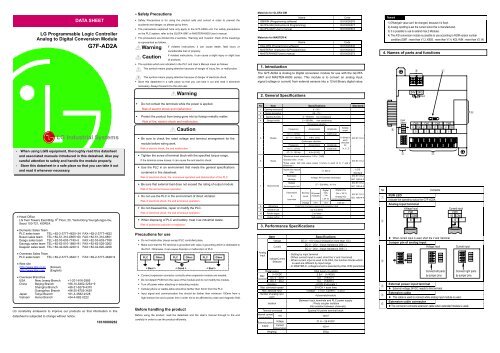
4. Names of parts and functions<br />
► The symbols which are indicated in the PLC and User’s Manual mean as follows<br />
This symbol means paying attention because of danger of injury, fire, or malfunction.<br />
This symbol means paying attention because of danger of electrical shock.<br />
► Store this datasheet in a safe place so that you can take it out and read it whenever<br />
1. Introduction<br />
The <strong>G7F</strong>-<strong>AD2A</strong> is Analog to Digital conversion module for use with the GLOFA<br />
GM7 and MASTER-K80S series. This module is to convert an analog input<br />
signal (voltage or current) from external sensors into a 12-bit Binary digital value,<br />
4<br />
1<br />
necessary. Always forward it to the end user.<br />
Warning<br />
2. General Specifications<br />
24V 24G<br />
Input<br />
<strong>LG</strong> <strong>Industrial</strong> <strong>Systems</strong><br />
- When using <strong>LG</strong>IS equipment, thoroughly read this datasheet<br />
and associated manuals introduced in this datasheet. Also pay<br />
careful attention to safety and handle the module properly.<br />
- Store this datasheet in a safe place so that you can take it out<br />
and read it whenever necessary.<br />
► Do not contact the terminals while the power is applied.<br />
Risk of electric shock and malfunction<br />
► Protect the product from being gone into by foreign metallic matter.<br />
Risk of fire, electric shock and malfunction.<br />
Caution<br />
► Be sure to check the rated voltage and terminal arrangement for the<br />
module before wiring work.<br />
Risk of electric shock, fire and malfunction<br />
► Tighten the screw of terminal block with the specified torque range.<br />
If the terminal screw looses, it can cause fire and electric shock.<br />
► Use the PLC in an environment that meets the general specifications<br />
contained in this datasheet.<br />
Risk of electrical shock, fire, erroneous operation and deterioration of the PLC.<br />
No Item Specifications Standard<br />
1 Operating temperature 0 ~ 55℃<br />
2 Storage temperature -25 ~ 75℃<br />
3 Operating Humidity 5 ~ 95%RH, non-condensing<br />
4 Storage humidity 5 ~ 95%RH, non-condensing<br />
5 Vibration<br />
6 Shocks<br />
Occasional vibration<br />
Frequency Acceleration Amplitude<br />
10≤f∠57 Hz - 0.075 mm<br />
57 ≤f≤150 Hz 9.8m∕s2 {1G} -<br />
Continuous vibration<br />
Frequency Acceleration Amplitude<br />
10≤f∠57 Hz - 0.035 mm<br />
57≤f≤150 Hz 4.9m∕s2{0.5G} -<br />
Sweep<br />
count<br />
10 times in<br />
each<br />
direction<br />
for<br />
X, Y, Z<br />
IEC 61131-2<br />
*Maximum shock acceleration: 147m∕s2 {15G}<br />
*Duration time :11 ms<br />
IEC 61131-2<br />
*Pulse wave: half sine wave pulse( 3 times in each of X, Y and Z<br />
directions )<br />
Square wave impulse<br />
noise<br />
Electrostatic<br />
discharge<br />
±1,500 V<br />
Voltage :4kV(contact discharge)<br />
<strong>LG</strong>IS<br />
Standard<br />
IEC 61131-2<br />
IEC 1000-4-2<br />
5<br />
Input<br />
Select<br />
CH3<br />
CH2<br />
V CH1 I<br />
CH0<br />
3<br />
CH0 CH1 CH2 CH3<br />
V0 COM0 V1 COM1 V2 COM2 V3 COM3<br />
I0 · I1 · I2 · I3 ·<br />
2<br />
6<br />
• Head Office<br />
<strong>LG</strong> Twin Towers East Bldg. 9 th Floor, 20, Yoido-Dong Youngdungpo-Gu,<br />
Seoul 150-721, KOREA<br />
• Domestic Sales Team<br />
PLC sales team TEL:+82-2-3777-4620~34 FAX:+82-2-3777-4622<br />
Busan sales team TEL:+82-51-310-6855~60 FAX:+82-51-310-6851<br />
Deagu sales team TEL:+82-53-603-7740~5 FAX:+82-53-603-7788<br />
Gaungju sales team TEL:+82-62-510-1885~91 FAX:+82-62-526-3262<br />
Deajeon sales team TEL:+82-42-820-4240~2 FAX:+82-42-820-4298<br />
• Overseas Sales Team<br />
PLC sales team TEL:+82-2-3777-4640~7 FAX:+82-2-3777-4648~9<br />
• Web site<br />
http://www.lgis.co.kr (Korean)<br />
http://www.lgis.com (English)<br />
• Overseas Branches<br />
USA New Jersey Branch +1-201-816-2985<br />
China Beijing Branch +86-10-6462-3254~9<br />
Shanghai Branch +86-21-6278-4370<br />
Guangzhou Branch +86-20-8755-3429<br />
Japan Tokyo Branch +81-3-3582-9128<br />
Vietnam Hanoi Branch +84-4-882-0222<br />
<strong>LG</strong> constantly endeavors to improve our products so that information in this<br />
datasheet is subjected to change without notice.<br />
10310000262<br />
► Be sure that external load does not exceed the rating of output module.<br />
Risk of fire and erroneous operation.<br />
► Do not use the PLC in the environment of direct vibration<br />
Risk of electrical shock, fire and erroneous operation.<br />
► Do not disassemble, repair or modify the PLC.<br />
Risk of electrical shock, fire and erroneous operation.<br />
► When disposing of PLC and battery, treat it as industrial waste.<br />
Risk of poisonous pollution or explosion.<br />
Precautions for use<br />
► Do not Install other places except PLC controlled place.<br />
► Make sure that the FG terminal is grounded with class 3 grounding which is dedicated to<br />
the PLC. Otherwise, it can cause disorder or malfunction of PLC<br />
PLC Others PLC Others PLC Others<br />
< Best ><br />
< Good > < Bad ><br />
► Connect expansion connector correctly when expansion module are needed,<br />
► Do not detach PCB from the case of the module and do not modify the module.<br />
► Turn off power when attaching or detaching module.<br />
► Cellular phone or walkie-talkie should be farther than 30cm from the PLC<br />
► Input signal and communication line should be farther than minimum 100mm from a<br />
high-tension line and a power line in order not to be affected by noise and magnetic field.<br />
Before handling the product<br />
Before using the product, read the datasheet and the User’s manual through to the end<br />
carefully in order to use the product efficiently.<br />
Radiated<br />
IEC 61131-2<br />
27 ~ 500 MHz, 10 V/m<br />
7 Noise immunity electromagnetic field<br />
IEC 1000-4-3<br />
Digital Digital I/Os<br />
Fast transient Severity All power I/Os (Ue < 24 V)<br />
Level modules ( Ue<br />
IEC 61131-2<br />
&<br />
Analog I/Os<br />
burst noise<br />
≥ 24 V)<br />
IEC 1000-4-4<br />
communication I/Os<br />
Voltage 2 kV 1 kV 0.25 kV<br />
8 Atmosphere Free from corrosive gases and excessive dust<br />
9 Altitude for use Up to 2,000m<br />
10 Pollution degree 2 or lower<br />
11 Cooling method Self-cooling<br />
3. Performance Specifications<br />
Analog<br />
Input<br />
Item<br />
Specifications<br />
Voltage DC 0∼10V (input resistance more than 1MΩ)<br />
Current<br />
Voltage/Current<br />
Selection<br />
DC 0∼20mA (input resistance 250Ω)<br />
DC 4∼20mA (input resistance 250Ω)<br />
- Setting by input terminal<br />
(When current input is used, short the V and I terminal)<br />
- When current input is used in GLOFA, the function blocks which<br />
is used are different by input range<br />
- In MASTER-K, voltage/current is selected by KGL-WIN parameter<br />
Digital output 12bit binary (0~4000)<br />
0~10VDC 2.5mV (1/4000)<br />
Max.<br />
DC 0∼20mA 5μA (1/4000 )<br />
resolution<br />
DC 4∼20mA 5μA (1/3200 )<br />
Accuracy ±0.5% [Full scale ]<br />
Max. conversion speed<br />
2ms/CH + scan time<br />
Max. absolute input Voltage : ±15V, Current : ±25mA<br />
Number of analog input<br />
point<br />
4channels/module<br />
Between Input terminals and PLC power supply<br />
Isolation<br />
: Photo coupler isolation<br />
(No isolation between channels)<br />
Terminal connected<br />
2points/16 points terminal block<br />
Internal current<br />
consumption<br />
+5V 100mA<br />
External power<br />
supply<br />
Weight(g)<br />
Voltage<br />
Current<br />
consumption<br />
21.6 ~ 26.4VDC<br />
100mA<br />
300g<br />
No<br />
1<br />
2<br />
3<br />
4<br />
5<br />
6<br />
RUN LED<br />
Contents<br />
Indicate the operating status the <strong>G7F</strong>-<strong>AD2A</strong><br />
Analog input terminal<br />
Voltage Input<br />
CH0<br />
V0 COM0<br />
I0 ·<br />
▶ When current input is used, short the V and I terminal.<br />
Jumper pin of analog input<br />
Voltage Input<br />
V<br />
CH3<br />
CH2<br />
CH1<br />
CHO<br />
External power input terminal<br />
Connect left parts<br />
by jumper pins<br />
▶ External voltage 24VDC needs to this terminal.<br />
Extension cable<br />
I<br />
Current input<br />
CH0<br />
V0 COM0<br />
I0 ·<br />
▶ This cable is used to connect while analog input module is used..<br />
Extension cable connector<br />
CH3<br />
CH2<br />
CH1<br />
CHO<br />
Current input<br />
Connect right parts<br />
by jumper pins<br />
▶The connector connects extension cable when extended module is used.<br />
CH3<br />
CH2<br />
CH1<br />
CHO
5. Function Block (only GLOFA series)<br />
5.1 Type of function block and function<br />
Function<br />
Remark<br />
block<br />
AD2_RD<br />
<strong>AD2A</strong>_RD<br />
AD2_420<br />
<strong>AD2A</strong>_420<br />
DC 0∼10V / DC 4∼20 mA Input only(single type)<br />
DC 0∼10V / DC 4∼20 mA Input only(array type)<br />
DC 4∼20 mA current input only(single type)<br />
DC 4∼20 mA current input only(array type)<br />
5.2 Reading A/D conversion value (AD2_RD, AD2_420)<br />
Single type of function block for reading the module is performed for only one channel<br />
and the specified channel is used to read output variable of data displayed from A/D<br />
converted digital value.<br />
Types of<br />
function block<br />
REQ<br />
SLOT<br />
CH<br />
V_I<br />
AD2_RD<br />
REQ<br />
SLOT<br />
CH<br />
Classifi<br />
Data<br />
Variable<br />
Contents<br />
cation<br />
type<br />
Execution request region of function block<br />
● If connected condition on then region is completed and<br />
REQ BOOL<br />
0 turns to 1, then function block of reading module is<br />
executed while the program is performing<br />
Location no. of slot<br />
SLOT USINT<br />
● Setting range:1 to 3<br />
Input<br />
Designation region of using channel<br />
CH BOOL<br />
● Setting range:0 to 3<br />
Designation region of Analog input type.<br />
●Setting range:0 or 1(0: Current selecting, 1:Voltage<br />
V_I BOOL<br />
selecting)<br />
★ It isn’t used in function block AD2_420<br />
Output DONE<br />
Indicating region of function block execution complete<br />
● If reading function block is completed to execute<br />
BOOL without an error then 1 is output and maintains 1 until<br />
next execution comes, but if an error occurs, 0 is<br />
output and if becomes operation stop status.<br />
STAT<br />
Area marking error status<br />
USINT<br />
● When error occurs, output error numbers.<br />
Area outputting A/D conversion value<br />
DATA INT<br />
● Data output range: 0 ∼ 4000<br />
5.3 Reading A/D conversion value (<strong>AD2A</strong>_RD, <strong>AD2A</strong>_420)<br />
Array type of function block for reading the module is performed for only one channel and the<br />
specified channel is used to read output variable of data displayed from A/D converted digital<br />
value.<br />
Type of<br />
function block<br />
REQ<br />
SLOT<br />
CH<br />
V_I<br />
DONE<br />
STAT<br />
DATA<br />
AD2_420<br />
STAT<br />
DATA<br />
<strong>AD2A</strong>_RD<br />
REQ<br />
SLOT<br />
CH<br />
DONE<br />
DONE<br />
STAT<br />
DATA<br />
<strong>AD2A</strong>_420<br />
DONE<br />
STAT<br />
DATA<br />
I/O<br />
Input<br />
Output<br />
Variable<br />
s<br />
REQ<br />
SLOT<br />
CH<br />
V_I<br />
DONE<br />
STAT<br />
DATA<br />
A/D conversion value stores special data register as following.<br />
Special data<br />
register<br />
Explanation<br />
D4980 A/D conversion value of channel 0 stores<br />
D4981<br />
D4982<br />
D4983<br />
D4984<br />
D4985<br />
D4986<br />
D4987<br />
Data<br />
Contents<br />
type<br />
Execution request region of function block<br />
● If connected condition on this region is completed and<br />
BOOL<br />
0 turns to 1 then function block of writing module is<br />
executed while the program is performing.<br />
Location no. of slot<br />
USINT<br />
● Setting range:1 to 3<br />
Designation region of using channel<br />
BOOL ● Setting range:0 to 3<br />
[Array] ● The number of element is 4, this number means<br />
channel number<br />
Designation region of Analog input type.<br />
●Setting range:0 or 1(0: Current selecting, 1:Voltage<br />
INT selecting)<br />
[Array] ● The number of element is 4, this number means<br />
channel number<br />
★ It isn’t used in function block AD2_420<br />
Indicating region of function block execution complete<br />
● If writing function block is completed to execute<br />
BOOL without an error then 1 is output and maintains 1 until<br />
nest execution comes, but if an error occurs, 0 is<br />
output and it becomes operation stop status<br />
Area for marking error status, that outputs error number when<br />
USINT<br />
error occurs in execution of function block.<br />
Area outputting A/D conversion value<br />
INT ● Data output range: 0 ∼ 4000<br />
[Array] ● The number of element is 4, this number means<br />
channel number<br />
6. Special data register (only MASTER-K series)<br />
A/D conversion value of channel 1 stores<br />
A/D conversion value of channel 2 stores<br />
A/D conversion value of channel 3 stores<br />
A/D conversion value of channel 0 stores<br />
A/D conversion value of channel 1 stores<br />
A/D conversion value of channel 2 stores<br />
A/D conversion value of channel 3 stores<br />
Remark<br />
Expansion A/D module #1<br />
Expansion A/D module #2<br />
7. Handling Precautions<br />
From unpacking to installation, be sure to check the following:<br />
1) Do not drop it off, and make sure that strong impacts should not be applied.<br />
2) Do not dismount printed circuit boards from the case. It can cause malfunctions.<br />
3) During wiring, be sure to check any foreign matter like wire scraps should not enter into the<br />
upper side of the PLC, and in the event that foreign matter entered into it, always eliminate it.<br />
4) Be sure to disconnect electrical power before mounting or dismounting the module.<br />
8. Wiring<br />
8.1 Caution for wiring<br />
▶Make sure that external input signal of the mixture module of AC and analog I/O is not<br />
affected by induction noise or occurs from the AC through using another cable.<br />
▶Wire is adopted with consideration about peripheral temperature and electric current<br />
allowance. Thicker than Max. size of wire AWG22 (0.3mm2) is better.<br />
▶If wire is put near to high temp. radiated device or contacted with oil for a long time, it may<br />
cause of electric leakage so that it gets broken or miss-operation during wiring.<br />
▶Be sure to connect with care of polarity while connecting to external 24V DC power supply.<br />
▶In case of wiring with high voltage line or generation line, it makes induction failure so then it<br />
may cause of miss-operation and out of order.<br />
8.2 Wiring<br />
*1 : Be sure to use two-core twisted shield wire.<br />
1) Voltage Input<br />
Digital output value<br />
4000<br />
2000<br />
0<br />
0V 5V 10V<br />
Analog input voltage<br />
A/D conversion characteristics (voltage input)<br />
In voltage input, digital amount 0 is output by 0V input and 4,000 is output by 10V input.<br />
Therefore input 2.5mV equals to digital amount 1, but value less than 2.5mV can’t be<br />
converted.<br />
2) Current Input<br />
Digital output value<br />
Analog<br />
Input<br />
4000<br />
2000<br />
Voltage Input<br />
*1<br />
0<br />
0 mA 5 mA 20 mA<br />
Analog input current<br />
Terminal<br />
V0<br />
+ +<br />
I0<br />
COM0<br />
9. I/O conversion characteristics<br />
Analog<br />
Input<br />
A/D conversion characteristics (Current input)<br />
Current input 0mA becomes output 0, 10mA does 2000 and 20mA does 4000. therefore<br />
input 5 μA equals to digital amount 1, but value less tan 5 μA can’t be converted. So<br />
abandon it.<br />
Digital output value<br />
Digital output value<br />
Current Input<br />
*1<br />
2004<br />
2003<br />
2002<br />
2001<br />
2000<br />
2004<br />
2003<br />
2002<br />
2001<br />
2000<br />
5.000V<br />
5.0025V<br />
10.000mA<br />
10.005mA<br />
input voltage<br />
input<br />
current<br />
Terminal<br />
V1<br />
I1<br />
COM1<br />
10. Dimension (unit : mm)<br />
Φ4.5<br />
GLOFA<br />
PROGRAMMABLE<br />
PWR<br />
LOGIC<br />
CONTROLLER<br />
95<br />
95 105 115<br />
5<br />
73<br />
11. Warranty<br />
1. Warranty period<br />
<strong>LG</strong>IS provides an 18-month-warranty from the date of the production.<br />
2. Warranty conditions<br />
For troubles within the warranty period, <strong>LG</strong>IS will replace the entire PLC or repair the<br />
troubled parts free of charge except the following cases.<br />
(1) The troubles caused by improper condition, environment or treatment except the<br />
instructions of <strong>LG</strong>IS.<br />
(2) The troubles caused by external devices.<br />
(3) The troubles caused by remodeling or repairing based on the user’s own discretion.<br />
(4) The troubles caused by improper usage of the product.<br />
(5) The troubles caused by the reason which exceeded the expectation from science and<br />
technology level when <strong>LG</strong>IS manufactured the product.<br />
(6) The troubles caused by natural disaster.<br />
3. This warranty is limited to the PLC itself only. It is not valid for the whole system which the<br />
PLC is attached to.