Cermark Super ViperJet MkII PART1 - RC Universe
Cermark Super ViperJet MkII PART1 - RC Universe
Cermark Super ViperJet MkII PART1 - RC Universe

You also want an ePaper? Increase the reach of your titles
YUMPU automatically turns print PDFs into web optimized ePapers that Google loves.
<strong>RC</strong>JI viperjet art. 11/3/05 12:58 pm Page 24<br />
VIPERJET<br />
MKII<br />
AUTHOR:<br />
KEITH WHIDDETT<br />
PHOTOGRAPHER:<br />
KEITH WHIDDETT<br />
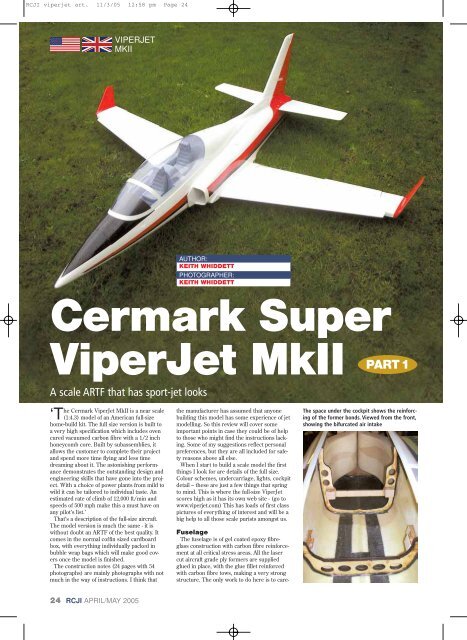
<strong>Cermark</strong> <strong>Super</strong><br />
<strong>ViperJet</strong> <strong>MkII</strong> PART 1<br />
A scale ARTF that has sport-jet looks<br />
he <strong>Cermark</strong> <strong>ViperJet</strong> <strong>MkII</strong> is a near scale<br />
‘T(1:4.3) model of an American full-size<br />
home-build kit. The full size version is built to<br />
a very high specification which includes oven<br />
cured vacuumed carbon fibre with a 1/2 inch<br />
honeycomb core. Built by subassemblies, it<br />
allows the customer to complete their project<br />
and spend more time flying and less time<br />
dreaming about it. The astonishing performance<br />
demonstrates the outstanding design and<br />
engineering skills that have gone into the project.<br />
With a choice of power plants from mild to<br />
wild it can be tailored to individual taste. An<br />
estimated rate of climb of 12,000 ft/min and<br />
speeds of 500 mph make this a must have on<br />
any pilot’s list.’<br />
That’s a description of the full-size aircraft.<br />
The model version is much the same - it is<br />
without doubt an ARTF of the best quality. It<br />
comes in the normal coffin sized cardboard<br />
box, with everything individually packed in<br />
bubble wrap bags which will make good covers<br />
once the model is finished.<br />
The construction notes (24 pages with 54<br />
photographs) are mainly photographs with not<br />
much in the way of instructions. I think that<br />
the manufacturer has assumed that anyone<br />
building this model has some experience of jet<br />
modelling. So this review will cover some<br />
important points in case they could be of help<br />
to those who might find the instructions lacking.<br />
Some of my suggestions reflect personal<br />
preferences, but they are all included for safety<br />
reasons above all else.<br />
When I start to build a scale model the first<br />
things I look for are details of the full size.<br />
Colour schemes, undercarriage, lights, cockpit<br />
detail – these are just a few things that spring<br />
to mind. This is where the full-size <strong>ViperJet</strong><br />
scores high as it has its own web site - (go to<br />
www.viperjet.com) This has loads of first class<br />
pictures of everything of interest and will be a<br />
big help to all those scale purists amongst us.<br />
Fuselage<br />
The fuselage is of gel coated epoxy fibreglass<br />
construction with carbon fibre reinforcement<br />
at all critical stress areas. All the laser<br />
cut aircraft grade ply formers are supplied<br />
glued in place, with the glue fillet reinforced<br />
with carbon fibre tows, making a very strong<br />
structure. The only work to do here is to care-<br />
The space under the cockpit shows the reinforcing<br />
of the former bonds. Viewed from the front,<br />
showing the bifurcated air intake<br />
24 <strong>RC</strong>JI APRIL/MAY 2005
<strong>RC</strong>JI viperjet art. 11/3/05 12:59 pm Page 25<br />
VIPERJET<br />
MKII<br />
Kit Specification<br />
Wing span: 74" (188 cm)<br />
Length: 80" (203 cm)<br />
Take-off weight: 22.25 lb (10 kg)<br />
Engine: 18-27 lb (80 – 120 Newtons)<br />
thrust<br />
Radio: 6-8 channel<br />
Servos: 8 required<br />
Basic components:<br />
Fuselage moulding and separate nosecone<br />
Engine hatch<br />
Tail-plane halves and elevators<br />
Wings, ailerons and flaps<br />
Fin and rudder<br />
Cockpit floor and canopy<br />
Equipment tray (in two parts)<br />
Servo mounts, control surface horns and<br />
retaining screws<br />
Engine by-pass<br />
Optional equipment:<br />
Winglets<br />
Ventral fins<br />
Conformal tanks<br />
Twin wall exhaust duct<br />
Retracts, legs, wheels and brakes<br />
Strobe lights<br />
Scale pilots<br />
Smoke system<br />
fully sand the joint between the two fuselage<br />
halves and touch-up the finish with an airbrush.<br />
The conformal tanks and the winglets shown here are optional extras – otherwise this is the basic kit<br />
Cockpit<br />
The cockpit is a nice piece of work. The<br />
seats are all formed in fibreglass, the floor is<br />
recessed below the canopy line, which gives a<br />
full depth impression, and a sheet of decals<br />
for the instrument panels finishes it off. All<br />
that is left to do is to find a pilot. I found one<br />
in a Carrefour supermarket while on holiday<br />
in Spain. Am I alone, when in the unfamiliar<br />
surroundings of a supermarket, in that I<br />
search for drinks’ bottles that will make fuel<br />
tanks, tea strainers that will become FOD<br />
guards and toy dolls to fill jet cockpits? I<br />
The nose-gear mounting tray bonds are also<br />
heavily reinforced<br />
The cockpit tub is glass fibre, not vac-formed ABS. The decals add realism<br />
Adapter plates and spacers will have to be made to suit the engine installed. These are for the<br />
Frank 70/14<br />
APRIL/MAY 2005 <strong>RC</strong>JI<br />
25
<strong>RC</strong>JI viperjet art. 11/3/05 1:48 pm Page 26<br />
VIPERJET<br />
MKII<br />
Fitting the bypass duct was simple. All that<br />
was needed was to cut slots in the sides to<br />
allow it to slip over the adaptor plates.<br />
The recommended engines are the JetCat<br />
P80 or the P120. I think that it would be asking<br />
too much of the P80 - it would no doubt fly<br />
it, but it would lack vertical performance.<br />
The Frank engine strap trial-fitted to the by-pass duct and engine mount<br />
Tanks<br />
There are three fibre glass conformal tanks<br />
supplied as optional extras, two of which go<br />
each side of the engine, the other sits in<br />
between the inlet ducting. All three are very<br />
close to the C of G so trim changes during<br />
flight should be a non-event. All three tanks<br />
have to be glued into place with silicone<br />
sealant but first be sure to roughen up the<br />
areas to be glued on both tank and fuselage to<br />
remove any traces of mould release.<br />
I employed my usual method of connecting<br />
each of the saddle tanks to a Y connector then<br />
connecting that to the central tank in order to<br />
minimise fuel flow restrictions.<br />
The central tank has the bung and feed pipes<br />
exiting at the top, which makes for a short<br />
length of pipe inside the tank. It is quite difficult<br />
to get the clunk to drop down to the “top”<br />
when the tank is inverted so I ended up wrapping<br />
solder around the clunk to increase its<br />
weight, which should help.<br />
No hopper tank was supplied and the central<br />
front tank could be connected directly to the<br />
fuel pump, in which case a membrane (filter)<br />
clunk of the Graupner or Orbit type would be<br />
preferred to the plain clunk. I choose to install<br />
a hopper tank, as recommended by <strong>Cermark</strong>,<br />
before the pump. Always try to keep fuel lines<br />
short to minimise restrictions.<br />
The three conformal fuel tanks are an essential<br />
option<br />
Weight has been added to the clunk fitted to<br />
the central tank<br />
found a suitable pilot and with a little surgery<br />
I soon had him in the seat complete with sunglasses<br />
and flying helmet. The pilot is one of<br />
the Power Elite team from the World<br />
Peacekeepers set. He is called the Helicopter<br />
Commander, should any body want one. The<br />
cost was 7!!<br />
Engine installation<br />
I found that the ply engine mounts were<br />
positioned too far apart for the Frank 70/14<br />
that I intend to use. I had to extend these by<br />
using 3 mm thick aluminium sheet bolted to<br />
the underside of the original mounts. A spacer<br />
was added to bring the engine up to the<br />
thrust line, ensuring that the by-pass duct<br />
lined up with the centre of the engine.<br />
Further checks found that the by-pass ducting<br />
was a snug fit between the factory installed<br />
ply mounts. It is now obvious that an engine<br />
big enough to fit without the need for adaptor<br />
plates would completely fill the by-pass! All<br />
engines will require adaptor plates and packers.<br />
For the record the gap between the<br />
mounts is 140 mm, the by-pass duct diameter<br />
is 132 mm and a JetCat P120 is 112 mm in<br />
diameter.<br />
Tail feathers<br />
Both the fin/rudder and tail-plane/elevators<br />
are made to a very high standard in gel-coated<br />
epoxy resin impregnated carbon fibre cloth.<br />
They come with the holes pre-drilled for the<br />
‘Robart’ pin hinges. I found that most of the<br />
holes were not drilled on the centreline and<br />
some were over-size. Holes requiring correction<br />
were opened out so that I could fill them<br />
with a piece of balsa glued into the over sized<br />
holes, which were then re-drilled to the correct<br />
size and on the centreline. For this<br />
process I find the Robart Hinge Jig a very useful<br />
tool as it aligns the hole to the centre as<br />
well as ensuring that the hole is square to the<br />
hinge line. I found that the inner Robart<br />
hinges on both tail-plane halves needed shortening<br />
as they protrude into the hole which has<br />
been left for the servo lead.<br />
I mass balanced the elevators before attaching<br />
them to the tailplane halves as a precaution<br />
against flutter. To do this I drilled a 5 mm hole<br />
into the side of each elevator aerodynamic balance<br />
tab. I took some ‘heavy powder’ which I<br />
had left over from my helicopter days. This was<br />
used for weighting rotor blades. I mixed 30<br />
gms of this with some epoxy resin, loaded it<br />
into a syringe and squeezed it into the hole.<br />
The elevator was held upright with the leading<br />
edge down so that the mass would solidify at<br />
the leading edge of the balance tab. I understand<br />
that heavy powder is no longer available<br />
so small shot would make a suitable substitute.<br />
There are two aluminium spars factory-fitted<br />
to each tailplane half that slide into tubing fixed<br />
in the fuselage. This leaves very little other<br />
work to do, just clean up the joint seams on tailplane<br />
halves and elevators and then install the<br />
26 <strong>RC</strong>JI APRIL/MAY 2005
<strong>RC</strong>JI viperjet art. 11/3/05 1:00 pm Page 27<br />
VIPERJET<br />
MKII<br />
Countersunk Allen head screws sit flush in load-bearing washers in the<br />
fuselage, retaining the tailplane<br />
Aileron and flap linkages with lock-nuts and clevis retainer sleeves all<br />
correctly fitted<br />
supplied epoxy fibre board horns in the elevators<br />
to line up with the servo output arms. I cut<br />
slots with a razor saw and epoxied the horns in<br />
place, taking care to make sure the holes in the<br />
horn lined up with the hinge line. The servos<br />
are fixed using the aluminium brackets supplied,<br />
and wooden blocks set in the pre-cut<br />
holes in the underside of the tailplane halves.<br />
The elevators and fin are held in the fuselage<br />
by counter sunk 3 mm bolts which screw into<br />
the aluminium spars previously mentioned. A<br />
nice metal insert is imbedded into the fuselage<br />
at each screw position which gives a positive<br />
and solid fixing. This also makes everything<br />
easy to take apart for transportation.<br />
Wings<br />
The wings are constructed in the same way<br />
as the tailplane. This really is quality moulding<br />
at its best. Only the joints between the wing<br />
upper and lower halves need cleaning up. The<br />
epoxy fibre board horns are installed in the<br />
same way as for the elevators. Again the holes<br />
for the Robart hinges for the ailerons and flaps<br />
An aileron and a flap servo will be fitted to the<br />
hatch cover. Note the glue on the protruding<br />
hinge ends<br />
are all pre-drilled, all you are left to do is glue<br />
them in. However, the factory-installed balsa<br />
blocks for the hinges are too small, in my opinion<br />
as the Robart hinges protrude 10 mm into<br />
the wing space, so when glue is put into the<br />
hole it is pushed out into the wing. It would<br />
have been much better to have had bigger<br />
blocks so that any glue put into the hinge hole<br />
would have remained in contact with the hinge.<br />
Before gluing any hinges always put a smear of<br />
Vaseline on to the pivot area to stop any glue<br />
from jamming them solid. I shall cross-pin my<br />
hinges to be sure that they will not pull out.<br />
When installing the flaps I had to remove<br />
some of the edge of the lower wing surface so<br />
that the flap did not foul the wing skin when<br />
fully deployed. I removed 3 mm to give me the<br />
required movement. The servo hatch is precut,<br />
the flap and aileron servos are mounted on<br />
the inside surface with the supplied aluminium<br />
brackets and wooden blocks. I found that if a<br />
servo is positioned in the middle of the hatch<br />
there is a good chance that it will foul the top<br />
wing skin. More space can be found for the<br />
servos by moving them forward.<br />
There is a very nice wing fairing that attaches<br />
to the root wing rib. This is simply put on over<br />
the wing root and super glued in place, making<br />
for a very nice transition from wing to fuselage.<br />
The winglets at the tips are pushed on and held<br />
in place with two bolts. A nice touch are the<br />
lenses for the lights or strobes, whichever you<br />
prefer to fit. I lined the inside of the lens cavities<br />
with sticky backed silver paper to act as a<br />
reflector for the lights that I will fit at a later<br />
date. A screened single core wire had been<br />
installed in each wing, this could be used to<br />
connect to the lights or strobes, but the screen<br />
would have to carry the electric current. It may<br />
be more sensible to use this wire as a pull-wire<br />
to pull in a screened two-core cable, especially<br />
if strobe lights are installed.<br />
All that remains is to install the landing gear<br />
and jet-pipe and test fly the aircraft. This will<br />
be described in the next issue. <br />
Likes<br />
A model which is very pleasing to the eye<br />
and a good choice of jet scale subject<br />
Big compartments for engine and radio<br />
installation<br />
Cockpit and seats, not made from ABS.<br />
Fixing of fin and tailplane, easily taken<br />
apart for transportation.<br />
General finish of the whole model<br />
Dislikes<br />
Instruction manual - very little in the way<br />
of written instructions<br />
Balsa blocks for pin hinges too small, but<br />
hinges could be pinned<br />
Optional extras could be included in the<br />
kit as they are all needed<br />
Contacts:<br />
Manufacturer: <strong>Cermark</strong>.<br />
e-mail: cermark@aol.com<br />
Technical Support: tamjets@yahoo.com<br />
UK distributor: CML Distribution<br />
www.cmldistribution.co.uk<br />
E-mail: cml@cmldistribution.co.uk<br />
Tel: 01527 575349<br />
APRIL/MAY 2005 <strong>RC</strong>JI<br />
27