Suggested Electric Fan Wiring Diagrams â DaveBarton.com
Suggested Electric Fan Wiring Diagrams â DaveBarton.com
Suggested Electric Fan Wiring Diagrams â DaveBarton.com

You also want an ePaper? Increase the reach of your titles
YUMPU automatically turns print PDFs into web optimized ePapers that Google loves.
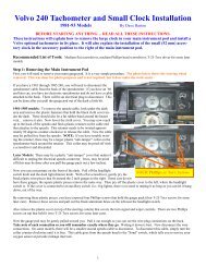
<strong>Suggested</strong> <strong>Electric</strong> <strong>Fan</strong> <strong>Wiring</strong> <strong>Diagrams</strong><br />
These diagrams show the use of relays, ON/OFF sensors, ON/OFF switches and ON/OFF fan<br />
controllers. Nothing here should be confused with the latest generation of VARIABLE SPEED<br />
CONTROLLERS, which generally have higher technology, such as a soft start feature, but not<br />
necessarily better durability.<br />
<strong>Suggested</strong> Primary Cooling <strong>Fan</strong> - Single Speed<br />
Using Ground Switching Devices Only for Primary Activation. A<br />
Ground Switched Device is one that provides a grounded output<br />
upon activation instead of a voltage output.<br />
Updated:<br />
02/13/2014<br />
SIGNAL CIRCUIT<br />
12V SWITCHED<br />
(IGNITION OR FUSE PANEL)<br />
Power “ON” when key is in the<br />
“RUN” position.<br />
5 AMP<br />
FUSE<br />
30<br />
85<br />
86<br />
87<br />
30 AMP<br />
FUSE<br />
1ST RELAY<br />
TURNS ON FAN<br />
WHEN TEMP<br />
SENSOR IS<br />
ACTIVATED<br />
BATTERY<br />
POWER SOURCE SHOULD BE<br />
BATTERY OR JUNCTION<br />
BLOCK NEAR BATTERY<br />
TEMP SENSOR<br />
SWITCH<br />
IN HOTTEST<br />
PART OF<br />
RADIATOR<br />
OR OPTIONAL<br />
ADJUSTABLE FAN<br />
SWITCH WITH<br />
RADIATOR PROBE<br />
(GROUND<br />
SWITCHING, NON-<br />
VARIABLE SPEED<br />
ONLY)<br />
FAN<br />
OPTIONAL 2ND RELAY<br />
OVERRIDES TEMP<br />
SENSOR AND TURNS<br />
ON FAN WHEN A/C IS<br />
TURNED ON<br />
30<br />
85<br />
86<br />
87<br />
RECOMMENDED WIRE SIZES:<br />
10-12 GA: FAN POWER AND<br />
GROUND.<br />
16-18 GA: ALL OTHERS.<br />
Relay Connections<br />
View from Bottom<br />
SPST Type<br />
30<br />
87b<br />
86<br />
85<br />
87<br />
STANDARD RELAY PINS<br />
30: Constant 12V, unswitched<br />
85: Signal (switched 12V)<br />
86: Ground (<strong>com</strong>petes circuit)<br />
87: Consumer (fan) 12V +<br />
87b: Extra consumer (same as 87)<br />
12V SWITCHED WIRE<br />
TO GREEN WIRE AT<br />
A/C CLUTCH.<br />
NOTE: OR IN AN ’84<br />
TO ‘89 240 YOU MAY<br />
USE THE A/C POWER<br />
‘ON’ WIRE:<br />
RED/WHITE WIRE AT<br />
AC SWITCH<br />
MICROSWITCH IN<br />
DASH.<br />
Optional override<br />
switch turns on all<br />
fans, by-passing temp<br />
sensor and A/C relay.<br />
SPST vs SPDT Relays. What’s the difference?<br />
Single Pole, Single Throw (SPST): This relay will be identified as having a middle 87b spade (or no middle<br />
spade at all). This is the most <strong>com</strong>mon relay used for fog lights or other simple circuits. If there is a middle 87b<br />
pin, it will have power whenever there is power to the 87 (whenever relay is “activated”). This way the middle 87b<br />
pin may be used as an extra power output.<br />
Single Pole, Double Throw (SPDT): If you have a relay with an 87a pin in the middle spot, it is a SPDT relay,<br />
sometimes called a "changeover relay." This type of relay will work for this application also, but you will not use<br />
pin 87a. In a changeover relay, the 87a pin will be “HOT” anytime the 87 pin is "OFF," so long as power is<br />
connected to pin 30.<br />
PAGE 1
<strong>Suggested</strong> <strong>Electric</strong> <strong>Fan</strong> <strong>Wiring</strong> <strong>Diagrams</strong><br />
These diagrams show the use of relays, ON/OFF sensors, ON/OFF switches and ON/OFF fan<br />
controllers. Nothing here should be confused with the latest generation of VARIABLE SPEED<br />
CONTROLLERS, which generally have higher technology, such as a soft start feature, but not<br />
necessarily better durability.<br />
<strong>Suggested</strong> Primary Cooling <strong>Fan</strong> - Single Speed<br />
Using 12 Volt Switching Devices Only for Primary Activation<br />
NOTE: Most stand-alone adjustable thermostats (i.e.: Hayden, Flex-a-Lite or Perma-Cool brands)<br />
provide a 12 volt output when activated. Also many do not require an external relay for minimal<br />
operation. External relays shown in these diagrams provide options for additional features, such as an<br />
AC override and/or manual override.<br />
12V SWITCHED WIRE<br />
TO GREEN WIRE AT<br />
A/C CLUTCH.<br />
NOTE: OR IN AN ’84<br />
TO ‘89 240 YOU MAY<br />
USE THE A/C POWER<br />
‘ON’ WIRE:<br />
RED/WHITE WIRE AT<br />
AC SWITCH<br />
MICROSWITCH IN<br />
DASH.<br />
OPTIONAL AC RELAY<br />
OVERRIDES TEMP SWITCH<br />
AND TURNS ON FAN<br />
WHEN A/C IS TURNED ON<br />
85<br />
87 30<br />
POWER SOURCE SHOULD BE<br />
BATTERY OR JUNCTION<br />
BLOCK NEAR BATTERY<br />
30 AMP<br />
FUSE<br />
BATTERY<br />
Optional override<br />
switch turns on fan,<br />
by-passing temp<br />
sensor and A/C relay.<br />
86<br />
30<br />
85<br />
86<br />
87<br />
1ST RELAY<br />
TURNS ON FAN<br />
WHEN TEMP<br />
SWITCH IS<br />
ACTIVATED<br />
SIGNAL CIRCUIT<br />
12V SWITCHED<br />
(IGNITION OR FUSE<br />
PANEL)<br />
Power “ON” when key is in<br />
the “RUN” position.<br />
Relay Connections<br />
View from Bottom<br />
SPST Type<br />
5 AMP<br />
FUSE<br />
+<br />
+<br />
ADJUSTABLE FAN<br />
SWITCH/THERMOSTAT<br />
WITH RADIATOR<br />
PROBE<br />
(12V SWITCHING,<br />
NON-VARIABLE SPEED<br />
ONLY)<br />
FAN<br />
86<br />
30<br />
87b<br />
85<br />
87<br />
STANDARD RELAY PINS<br />
30: Constant 12V, unswitched<br />
85: Signal (switched 12V)<br />
86: Ground (<strong>com</strong>petes circuit)<br />
87: Consumer (fan) 12V +<br />
87b: Extra consumer (same as 87)<br />
RECOMMENDED WIRE SIZES:<br />
10-12 GA: FAN POWER AND<br />
GROUND.<br />
16-18 GA: ALL OTHERS.<br />
SPST vs SPDT Relays. What’s the difference?<br />
Single Pole, Single Throw (SPST): This relay will be identified as having a middle 87b spade (or no middle<br />
spade at all). This is the most <strong>com</strong>mon relay used for fog lights or other simple circuits. If there is a middle 87b<br />
pin, it will have power whenever there is power to the 87 (whenever relay is “activated”). This way the middle 87b<br />
pin may be used as an extra power output.<br />
Single Pole, Double Throw (SPDT): If you have a relay with an 87a pin in the middle spot, it is a SPDT relay,<br />
sometimes called a "changeover relay." This type of relay will work for this application also, but you will not use<br />
pin 87a. In a changeover relay, the 87a pin will be “HOT” anytime the 87 pin is "OFF," so long as power is<br />
connected to pin 30.<br />
PAGE 2
<strong>Suggested</strong> <strong>Electric</strong> <strong>Fan</strong> <strong>Wiring</strong> <strong>Diagrams</strong><br />
These diagrams show the use of relays, ON/OFF switches and ON/OFF fan controllers. Nothing here<br />
should be confused with the latest generation of VARIABLE SPEED CONTROLLERS, which generally<br />
have higher technology, such as soft start, but not necessarily better durability.<br />
Converting a 12 Volt Switch into a Ground Switch<br />
If you have an adjustable thermostat that uses 12 VOLT SWITCHING, such as the popular<br />
Hayden brand thermostats, you may use it with any diagram showing a need for a GROUND<br />
SWITCHED DEVICE if you follow these steps to convert it using a simple SPST relay.<br />
THIS WILL BE YOUR NEW<br />
GROUND SWITCH OUTPUT.<br />
IT MAY BE USED AS A GROUND<br />
SWITCHED DEVICE FOR ANY<br />
DIAGRAM NEEDING ONE.<br />
30<br />
86<br />
87<br />
85<br />
SIGNAL CIRCUIT<br />
12V SWITCHED<br />
(IGNITION OR FUSE<br />
PANEL)<br />
Power “ON” when key is in<br />
the “RUN” position.<br />
5 AMP<br />
FUSE<br />
+<br />
+<br />
ADJUSTABLE FAN<br />
SWITCH/THERMOSTAT<br />
WITH RADIATOR<br />
PROBE<br />
(12V SWITCHING,<br />
NON-VARIABLE SPEED<br />
ONLY)<br />
Relay Connections<br />
View from Bottom<br />
SPST Type<br />
86<br />
RECOMMENDED WIRE SIZES:<br />
10-12 GA: FAN POWER AND<br />
GROUND.<br />
16-18 GA: ALL OTHERS.<br />
30<br />
87b<br />
85<br />
87<br />
STANDARD RELAY PINS<br />
30: Constant 12V, unswitched<br />
85: Signal (switched 12V)<br />
86: Ground (<strong>com</strong>petes circuit)<br />
87: Consumer (fan) 12V +<br />
87b: Extra consumer (same as 87)<br />
SPST vs SPDT Relays. What’s the difference?<br />
Single Pole, Single Throw (SPST): This relay will be identified as having a middle 87b spade (or no middle<br />
spade at all). This is the most <strong>com</strong>mon relay used for fog lights or other simple circuits. If there is a middle 87b<br />
pin, it will have power whenever there is power to the 87 (whenever relay is “activated”). This way the middle 87b<br />
pin may be used as an extra power output.<br />
Single Pole, Double Throw (SPDT): If you have a relay with an 87a pin in the middle spot, it is a SPDT relay,<br />
sometimes called a "changeover relay." This type of relay will work for this application also, but you will not use<br />
pin 87a. In a changeover relay, the 87a pin will be “HOT” anytime the 87 pin is "OFF," so long as power is<br />
connected to pin 30.<br />
PAGE 3
PRIMARY COOLING FAN<br />
DUAL FANS (with Dual Relays)<br />
Using Ground Switched Devices Only for Primary Activation<br />
Using dual relays for two fans is not required. You could use one relay. However two relays<br />
will divide the load and if a relay fails, you will still have one fan running.<br />
SIGNAL<br />
12V SWITCHED<br />
(FUSE PANEL)<br />
Power “ON” when<br />
key is in the<br />
“RUN” position<br />
5 AMP<br />
FUSE<br />
30<br />
85<br />
30AMP<br />
FUSE<br />
86<br />
87<br />
30AMP<br />
FUSE<br />
BATTERY<br />
MAIN RELAYS<br />
TURN ON FANS<br />
WHEN TEMP<br />
SENSOR IS<br />
ACTIVATED<br />
POWER SOURCE SHOULD BE<br />
BATTERY OR JUNCTION<br />
BLOCK NEAR BATTERY<br />
TEMP SENSOR<br />
SWITCH<br />
IN HOTTEST<br />
PART OF<br />
RADIATOR<br />
OR OPTIONAL<br />
ADJUSTABLE FAN<br />
SWITCH WITH<br />
RADIATOR PROBE<br />
(GROUND<br />
SWITCHING, NON-<br />
VARIABLE SPEED<br />
ONLY)<br />
30<br />
85<br />
86<br />
87<br />
30<br />
85<br />
86<br />
87<br />
OPTIONAL RELAY<br />
OVERRIDES TEMP<br />
SENSOR AND<br />
TURNS ON FANS<br />
WHEN A/C IS<br />
TURNED ON<br />
Relay Connections<br />
View from Bottom<br />
SPST Type<br />
86<br />
FAN 1<br />
FAN 2<br />
12V SWITCHED WIRE.<br />
MAY BE GREEN WIRE<br />
AT A/C CLUTCH.<br />
NOTE: OR IN AN ’84<br />
TO ‘89 240 YOU MAY<br />
USE THE A/C POWER<br />
‘ON’ WIRE: RED/WHITE<br />
WIRE AT AC SWITCH<br />
MICROSWITCH IN<br />
DASH.<br />
30<br />
87b<br />
87<br />
Optional override switch<br />
turns on fan, by-passing<br />
temp sensor and A/C relay.<br />
85<br />
STANDARD RELAY PINS<br />
30: Constant 12V, unswitched<br />
85: Signal (switched 12V)<br />
86: Ground (<strong>com</strong>petes circuit)<br />
87: Consumer (fan) 12V +<br />
87b: Extra consumer (same as 87)<br />
RECOMMENDED WIRE SIZES:<br />
10-12 GA: FAN POWER AND<br />
GROUND.<br />
16-18 GA: ALL OTHERS.<br />
PAGE 4
PRIMARY COOLING FAN<br />
DUAL FANS (with Dual Relays)<br />
Using 12 Volt Switched Devices Only for Primary Activation<br />
Using dual relays for two fans is not required. You could use one relay. However two relays<br />
will divide the load and if a relay fails, you will still have one fan running.<br />
12V SWITCHED WIRE<br />
TO GREEN WIRE AT<br />
A/C CLUTCH.<br />
NOTE: OR IN AN ’84<br />
TO ‘89 240 YOU MAY<br />
USE THE A/C POWER<br />
‘ON’ WIRE:<br />
RED/WHITE WIRE AT<br />
AC SWITCH<br />
MICROSWITCH IN<br />
DASH.<br />
Optional override<br />
switch turns on fans,<br />
by-passing temp<br />
sensor and A/C relay.<br />
OPTIONAL AC RELAY<br />
OVERRIDES TEMP SWITCH<br />
AND TURNS ON FANS<br />
WHEN A/C IS<br />
TURNED ON<br />
86<br />
85<br />
87 30<br />
30<br />
85<br />
POWER SOURCE SHOULD BE<br />
BATTERY OR JUNCTION<br />
BLOCK NEAR BATTERY<br />
86<br />
30 AMP<br />
FUSE<br />
30 AMP<br />
FUSE<br />
87<br />
BATTERY<br />
MAIN RELAYS<br />
TURN ON FANS<br />
WHEN TEMP<br />
SWITCH IS<br />
ACTIVATED<br />
SIGNAL CIRCUIT<br />
12V SWITCHED<br />
(IGNITION OR FUSE<br />
PANEL)<br />
Power “ON” when key is in<br />
the “RUN” position.<br />
5 AMP<br />
FUSE<br />
+<br />
+<br />
FAN 1<br />
ADJUSTABLE FAN<br />
SWITCH/THERMOSTAT<br />
WITH RADIATOR<br />
PROBE<br />
(12V SWITCHING,<br />
NON-VARIABLE SPEED<br />
ONLY)<br />
30<br />
85<br />
86<br />
87<br />
FAN 2<br />
Relay Connections<br />
View from Bottom<br />
SPST Type<br />
RECOMMENDED WIRE SIZES:<br />
10-12 GA: FAN POWER AND<br />
GROUND.<br />
16-18 GA: ALL OTHERS.<br />
86<br />
30<br />
87b<br />
85<br />
87<br />
STANDARD RELAY PINS<br />
30: Constant 12V, unswitched<br />
85: Signal (switched 12V)<br />
86: Ground (<strong>com</strong>petes circuit)<br />
87: Consumer (fan) 12V +<br />
87b: Extra consumer (same as 87)<br />
PAGE 5
SINGLE A/C FAN ONLY<br />
Pusher for A/C Condenser<br />
This diagram works well if you only wish to add a single fan to the front<br />
of your A/C condenser. It will not <strong>com</strong>e on at a particular temperature,<br />
but only when the A/C is turned on.<br />
30AMP<br />
FUSE<br />
POWER SOURCE SHOULD BE<br />
BATTERY OR JUNCTION<br />
BLOCK NEAR BATTERY<br />
86<br />
BATTERY<br />
RECOMMENDED WIRE SIZES:<br />
10-12 GA: FAN POWER AND<br />
GROUND.<br />
16-18 GA: ALL OTHERS.<br />
30<br />
85<br />
87<br />
Relay Connections<br />
View from Bottom<br />
SPST Type<br />
5 AMP<br />
FUSE<br />
86<br />
12V SWITCHED WIRE TO GREEN<br />
WIRE AT A/C CLUTCH.<br />
NOTE: OR IN AN ’84 TO ’89 240<br />
YOU MAY USE THE A/C<br />
CONSTANT ‘ON’ WIRE: RED/<br />
WHITE WIRE AT AC<br />
MICROSWITCH IN DASH.<br />
THIS PERMITS THE FAN TO RUN<br />
CONSTANT ANYTIME THE A/C<br />
SWITCH IS IN THE “ON”<br />
POSITION.<br />
(I.E.: FAN WILL NOT CYCLE ON/<br />
OFF WHEN COMPRESSOR<br />
DOES).<br />
AC<br />
FAN<br />
30<br />
87b<br />
85<br />
87<br />
STANDARD RELAY PINS<br />
30: Constant 12V, unswitched<br />
85: Signal (switched 12V)<br />
86: Ground (<strong>com</strong>petes circuit)<br />
87: Consumer (fan) 12V +<br />
87b: Extra consumer (same as 87)<br />
PAGE 6
Primary Cooling <strong>Fan</strong> - Two Speed Type<br />
Using Ground Switched Devices Only for Primary Activation<br />
SIGNAL CIRCUIT<br />
12V SWITCHED<br />
(IGNITION OR FUSE<br />
PANEL)<br />
Power “ON” when key is<br />
in the “RUN” position.<br />
5 AMP<br />
FUSE<br />
BATTERY<br />
POWER SOURCE SHOULD BE<br />
BATTERY OR JUNCTION<br />
BLOCK NEAR BATTERY<br />
40 AMP<br />
FUSE<br />
HIGH RANGE TEMP SENSOR<br />
SET FOR 200 DEG F OR HIGHER<br />
TEMP SENSOR<br />
SWITCH<br />
IN RADIATOR<br />
OR OPTIONAL ADJUSTABLE FAN<br />
SWITCH WITH RADIATOR PROBE<br />
(GROUND SWITCHING,<br />
NON-VARIABLE SPEED)<br />
86<br />
RELAY #3:<br />
CHANGEOVER<br />
SPDT TYPE<br />
30<br />
85<br />
87a<br />
87<br />
TEMP SENSOR<br />
SWITCH<br />
IN RADIATOR<br />
LOW RANGE TEMP SENSOR<br />
SET FOR 180 to 190 DEG F<br />
OR OPTIONAL ADJUSTABLE FAN<br />
SWITCH WITH RADIATOR PROBE<br />
(GROUND SWITCHING,<br />
NON-VARIABLE SPEED)<br />
RELAY #1:<br />
HIGH SPEED<br />
40A to 70A<br />
30<br />
86<br />
87<br />
30<br />
86<br />
RELAY #2:<br />
LOW SPEED<br />
30A<br />
87<br />
Relay Connections<br />
View from Bottom<br />
SPST Type (87b)<br />
SPDT Type (87a)<br />
86<br />
85<br />
85<br />
30<br />
87<br />
HIGH SPEED<br />
RECOMMENDED WIRE SIZES:<br />
10-12 GA: FAN POWER AND<br />
GROUND.<br />
16-18 GA: ALL OTHERS.<br />
87b<br />
or<br />
87a<br />
85<br />
FAN<br />
LOW SPEED<br />
Optional override<br />
switch turns on<br />
fan to high speed,<br />
by-passing temp<br />
sensor.<br />
STANDARD RELAY PINS<br />
30: Constant 12V, unswitched<br />
85: Signal (switched 12V)<br />
86: Ground (<strong>com</strong>petes circuit)<br />
87: Consumer (fan) 12V +<br />
87b: Extra consumer (same as 87)<br />
87a: Opposite of 87 (changeover)<br />
TWO SPEED FAN CIRCUITRY SIMPLIFIED<br />
This is not as confusing as it looks. A two-speed fan may be used as long as you use THREE relays and TWO<br />
temperature sensors set for different set points.<br />
The fan will remain off until your low temperature set point is reached, activating the low speed relay. If your temperature<br />
climbs higher, the second sensor high set point will activate the changeover relay, sending power to the high speed<br />
relay, while at the same time shutting off the low speed circuit. This way you can be sure only one circuit will be on at a<br />
time.<br />
The high speed relay capacity will depend on the fan. Most 16 inch or smaller fans can get by with a 40A relay for the high<br />
speed. A larger fan, such as the 18 to 19 inch Ford Taurus/T-Bird/Lincoln Mk VIII fans, should use a 70A relay. These fans<br />
generally use 35 to 40 amps, so power and ground cables for these big fans should be at least 10 GA.<br />
Simple radiator coolant sensors may be used as long as they are different temperature ranges. Or simple electric<br />
adjustable ON/OFF fan controllers can be purchased from Summit Racing for about $35 each.<br />
PAGE 7
Primary Cooling <strong>Fan</strong> - Two Speed Type<br />
Using 12 Volt Switching Devices Only for Primary Activation<br />
Optional override<br />
switch turns on<br />
fan to high speed,<br />
by-passing temp<br />
sensor.<br />
SIGNAL CIRCUIT<br />
12V SWITCHED<br />
(IGNITION OR FUSE<br />
PANEL)<br />
Power “ON” when key is<br />
in the “RUN” position.<br />
HIGH RANGE THERMOSTAT<br />
SET FOR 200 DEG F OR HIGHER<br />
12V SWITCHING,<br />
NON-VARIABLE SPEED ONLY<br />
5 AMP<br />
FUSE<br />
+<br />
+<br />
BATTERY<br />
30<br />
85<br />
POWER SOURCE SHOULD BE<br />
BATTERY OR JUNCTION<br />
BLOCK NEAR BATTERY<br />
87a<br />
86<br />
87<br />
40 AMP<br />
FUSE<br />
RELAY #3:<br />
CHANGEOVER<br />
SPDT TYPE<br />
RELAY #1:<br />
HIGH SPEED<br />
40A to 70A<br />
86<br />
86<br />
RELAY #2:<br />
LOW SPEED<br />
30A<br />
30<br />
87<br />
LOW RANGE THERMOSTAT<br />
SET FOR 180 to 190 DEG F<br />
30<br />
87<br />
85<br />
12V SWITCHING,<br />
NON-VARIABLE SPEED ONLY<br />
+<br />
+<br />
85<br />
Relay Connections<br />
View from Bottom<br />
SPST Type (87b)<br />
SPDT Type (87a)<br />
86<br />
HIGH SPEED<br />
RECOMMENDED WIRE SIZES:<br />
10-12 GA: FAN POWER AND<br />
GROUND.<br />
16-18 GA: ALL OTHERS.<br />
30<br />
87b<br />
or<br />
87a<br />
85<br />
87<br />
STANDARD RELAY PINS<br />
30: Constant 12V, unswitched<br />
85: Signal (switched 12V)<br />
86: Ground (<strong>com</strong>petes circuit)<br />
87: Consumer (fan) 12V +<br />
87b: Extra consumer (same as 87)<br />
FAN<br />
LOW SPEED<br />
TWO SPEED FAN CIRCUITRY SIMPLIFIED<br />
This is not as confusing as it looks. A two-speed fan may be used as long as you use THREE relays and TWO<br />
temperature sensors set for different set points.<br />
The fan will remain off until your low temperature set point is reached, activating the low speed relay. If your temperature<br />
climbs higher, the second sensor high set point will activate the changeover relay, sending power to the high speed<br />
relay, while at the same time shutting off the low speed circuit. This way you can be sure only one circuit will be on at a<br />
time.<br />
The high speed relay capacity will depend on the fan. Most 16 inch or smaller fans can get by with a 40A relay for the high<br />
speed. A larger fan, such as the 18 to 19 inch Ford Taurus/T-Bird/Lincoln Mk VIII fans, should use a 70A relay. These fans<br />
generally use 35 to 40 amps, so power and ground cables for these big fans should be at least 10 GA.<br />
For the diagram above, simple electric adjustable ON/OFF 12 volt switched fan controllers can be purchased from<br />
Summit Racing for about $35 each.<br />
PAGE 8
Primary Cooling <strong>Fan</strong> - Two Speed Type<br />
Using Ground Switched Devices Only for Primary Activation<br />
Same as diagram on Page 7, except I have added a circuit at the<br />
bottom for your AC to activate the LOW SPEED FAN.<br />
SIGNAL CIRCUIT<br />
12V SWITCHED<br />
(IGNITION OR FUSE<br />
PANEL)<br />
Power “ON” when key is<br />
in the “RUN” position.<br />
5 AMP<br />
FUSE<br />
BATTERY<br />
POWER SOURCE SHOULD BE<br />
BATTERY OR JUNCTION<br />
BLOCK NEAR BATTERY<br />
40 AMP<br />
FUSE<br />
HIGH RANGE TEMP SENSOR<br />
SET FOR 200 DEG F OR HIGHER<br />
TEMP SENSOR<br />
SWITCH<br />
IN RADIATOR<br />
OR OPTIONAL ADJUSTABLE FAN<br />
SWITCH WITH RADIATOR PROBE<br />
(GROUND SWITCHING,<br />
NON-VARIABLE SPEED)<br />
86<br />
RELAY #3:<br />
CHANGEOVER<br />
SPDT TYPE<br />
30<br />
85<br />
87a<br />
87<br />
TEMP SENSOR<br />
SWITCH<br />
IN RADIATOR<br />
LOW RANGE TEMP SENSOR<br />
SET FOR 180 to 190 DEG F<br />
OR OPTIONAL ADJUSTABLE FAN<br />
SWITCH WITH RADIATOR PROBE<br />
(GROUND SWITCHING,<br />
NON-VARIABLE SPEED)<br />
RELAY #1:<br />
HIGH SPEED<br />
40A to 70A<br />
30<br />
86<br />
87<br />
30<br />
86<br />
RELAY #2:<br />
LOW SPEED<br />
30A<br />
87<br />
Relay Connections<br />
View from Bottom<br />
SPST Type (87b)<br />
SPDT Type (87a)<br />
86<br />
85<br />
85<br />
30<br />
87<br />
HIGH SPEED<br />
RECOMMENDED WIRE SIZES:<br />
10-12 GA: FAN POWER AND<br />
GROUND.<br />
16-18 GA: ALL OTHERS.<br />
87b<br />
or<br />
87a<br />
85<br />
FAN<br />
LOW SPEED<br />
Optional override<br />
switch turns on<br />
fan to high speed,<br />
by-passing temp<br />
sensor.<br />
STANDARD RELAY PINS<br />
30: Constant 12V, unswitched<br />
85: Signal (switched 12V)<br />
86: Ground (<strong>com</strong>petes circuit)<br />
87: Consumer (fan) 12V +<br />
87b: Extra consumer (same as 87)<br />
87a: Opposite of 87 (changeover)<br />
12V SWITCHED WIRE<br />
OR GREEN WIRE AT<br />
A/C CLUTCH.<br />
NOTE: OR IN AN ’84<br />
TO ‘89 240 YOU MAY<br />
USE THE A/C POWER<br />
‘ON’ WIRE:<br />
RED/WHITE WIRE AT<br />
AC SWITCH<br />
MICROSWITCH IN<br />
DASH.<br />
30<br />
85<br />
86<br />
87<br />
OPTIONAL RELAY<br />
OVERRIDES TEMP SENSOR AND<br />
TURNS ON LOW SPEED FAN WHEN<br />
A/C IS TURNED ON<br />
PAGE 9
Primary Cooling <strong>Fan</strong> - Two Speed Type<br />
Using 12 Volt Switching Devices Only for Primary Activation<br />
Same as diagram on Page 7, except I have added a circuit at the<br />
bottom for your AC to activate the LOW SPEED FAN.<br />
Optional override<br />
switch turns on<br />
fan to high speed,<br />
by-passing temp<br />
sensor.<br />
SIGNAL CIRCUIT<br />
12V SWITCHED<br />
(IGNITION OR FUSE<br />
PANEL)<br />
Power “ON” when key is<br />
in the “RUN” position.<br />
HIGH RANGE THERMOSTAT<br />
SET FOR 200 DEG F OR HIGHER<br />
12V SWITCHING,<br />
NON-VARIABLE SPEED ONLY<br />
5 AMP<br />
FUSE<br />
+<br />
+<br />
BATTERY<br />
30<br />
85<br />
POWER SOURCE SHOULD BE<br />
BATTERY OR JUNCTION<br />
BLOCK NEAR BATTERY<br />
87a<br />
86<br />
87<br />
40 AMP<br />
FUSE<br />
RELAY #3:<br />
CHANGEOVER<br />
SPDT TYPE<br />
RELAY #1:<br />
HIGH SPEED<br />
40A to 70A<br />
86<br />
RECOMMENDED WIRE SIZES:<br />
10-12 GA: FAN POWER AND<br />
GROUND.<br />
16-18 GA: ALL OTHERS.<br />
86<br />
RELAY #2:<br />
LOW SPEED<br />
30A<br />
30<br />
87<br />
LOW RANGE THERMOSTAT<br />
SET FOR 180 to 190 DEG F<br />
30<br />
87<br />
85<br />
12V SWITCHING,<br />
NON-VARIABLE SPEED ONLY<br />
+<br />
+<br />
85<br />
Relay Connections<br />
View from Bottom<br />
SPST Type (87b)<br />
SPDT Type (87a)<br />
HIGH SPEED<br />
86<br />
30<br />
87b<br />
or<br />
87a<br />
85<br />
87<br />
STANDARD RELAY PINS<br />
30: Constant 12V, unswitched<br />
85: Signal (switched 12V)<br />
86: Ground (<strong>com</strong>petes circuit)<br />
87: Consumer (fan) 12V +<br />
87b: Extra consumer (same as 87)<br />
FAN<br />
LOW SPEED<br />
12V SWITCHED AC<br />
WIRE OR GREEN WIRE<br />
AT A/C CLUTCH.<br />
NOTE: OR IN AN ’84<br />
TO ‘89 240 YOU MAY<br />
USE THE A/C POWER<br />
‘ON’ WIRE:<br />
RED/WHITE WIRE AT<br />
AC SWITCH<br />
MICROSWITCH IN<br />
DASH.<br />
12V<br />
POWER<br />
SOURCE<br />
87 30<br />
86<br />
85<br />
OPTIONAL RELAY<br />
OVERRIDES TEMP SENSOR AND<br />
TURNS ON LOW SPEED FAN WHEN<br />
A/C IS TURNED ON<br />
PAGE 10