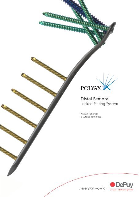
POLYAX Distal Femoral Locked Plating System Product ... - Biomet
POLYAX Distal Femoral Locked Plating System Product ... - Biomet
POLYAX Distal Femoral Locked Plating System Product ... - Biomet

Create successful ePaper yourself
Turn your PDF publications into a flip-book with our unique Google optimized e-Paper software.
<strong>Distal</strong> <strong>Femoral</strong><br />
<strong>Locked</strong> <strong>Plating</strong> <strong>System</strong><br />
<strong>Product</strong> Rationale<br />
& Surgical Technique<br />
3
Contents<br />
Surgeon Design Team 2<br />
Introduction 3<br />
<strong>Distal</strong> <strong>Femoral</strong> <strong>Locked</strong> <strong>Plating</strong> <strong>System</strong> - Features and Benefits 4<br />
Locking Options 6<br />
Surgical Technique 7<br />
Incision 8<br />
Percutaneous Approach and Plate Placement 9<br />
Preliminary Fixation 10<br />
3.2 mm Guide Pin Placement 11<br />
Varus-Valgus Correction 12<br />
8.0 mm Cannulated Locking Screw 14<br />
5.5 mm Cancellous Locking and Non-Locking Screws 16<br />
4.5 mm Non-Locking Shaft Screws 20<br />
4.5 mm Locking Shaft Screws 22<br />
Ordering Information 25<br />
1
Surgeon Design Team<br />
Lawrence Bone, MD<br />
Professor and Chairman<br />
Department of Orthopaedic Surgery<br />
State University of New York at Buffalo<br />
George Haidukewych, MD<br />
Orthopaedic Traumatologist<br />
Adult Reconstruction Surgeon<br />
Florida Orthopaedic Institute<br />
Roy Sanders, MD<br />
Chief, Department of Orthopaedics<br />
Tampa General Hospital<br />
Director, Orthopaedic Trauma Service<br />
Florida Orthopaedic Institute<br />
2
Introduction<br />
The <strong>POLYAX</strong> <strong>Locked</strong> <strong>Plating</strong> <strong>System</strong> is indicated for the treatment of distal<br />
femoral and proximal tibial fractures. Designed to give the surgeon maximum<br />
flexibility with the use of fixed-angle locking, variable-angle locking and nonlocking<br />
screw options. The result is fracture fixation based on each individual<br />
patient’s fracture type, bone quality and anatomy.<br />
Each plate is manufactured from TIMAX anodised titanium alloy Ti-6Al-4V,<br />
which gives the plates superior fatigue strength, excellent biocompatibility and<br />
optimal stress transfer. The screws are manufactured from colour-anodised<br />
titanium alloy Ti-6Al-4V for easy identification and selection in the OR.<br />
Indications<br />
The <strong>POLYAX</strong> <strong>Locked</strong> <strong>Plating</strong> <strong>System</strong> is intended for use in cases requiring<br />
stabilisation of malunions, non-unions, and osteotomies of the distal femur<br />
and proximal tibia. It is also intended for Open Reduction Internal Fixation<br />
(ORIF) repair of closed and open fractures of the distal femur and proximal<br />
tibia including, but not limited to the following periarticular fractures,<br />
such as:<br />
• simple comminuted<br />
• lateral wedge<br />
• depression<br />
• medial wedge<br />
• bicondylar<br />
• combinations of lateral wedge and depression fractures with associated<br />
shaft fractures, and periprosthetic fractures<br />
3
<strong>Distal</strong> <strong>Femoral</strong> <strong>Locked</strong> <strong>Plating</strong> <strong>System</strong><br />
Polyaxial Screw Technology<br />
The screw and plate technology allows for freedom of screw position<br />
at any desired angle within a 30˚ cone of angulation. This patented<br />
technology also allows for locking and lag screw options.<br />
Multiple Options for Fixation<br />
The plates have maximum stability and fixation with multiple<br />
screw options; self-tapping, variable-angle locking, fixed-angle<br />
locking, non-locking, cortical, cancellous, unicortical and bicortical.<br />
Tapered Triple<br />
Lead Locking Thread<br />
Single Lead Thread<br />
Buttress Thread Form<br />
Self-tapping Tip<br />
Colour-Coded Screws and Instrumentation<br />
A minimal amount of instrumentation is required,<br />
allowing for ease of use and familiarity in the OR.<br />
The instrumentation and screws are colour-coded<br />
for easy identification and selection in the surgery.<br />
4
Stable Locking Fixation<br />
Screw locking is accomplished either by threading a screw<br />
directly into the plate (fixed-angle construct) or into a patented<br />
polyaxial bushing (variable-angle construct) contained within<br />
the plate. The screws locking portion consists of a triple-lead,<br />
tapered-thread on the screw head, which is designed to engage<br />
the plate or bushings. The bushings allow the surgeon to lock<br />
screws in place at a desired angle within a maximum 30˚ cone<br />
of angulation. Non-Locking screws are provided for placement<br />
in either a fixed locking hole or polyaxial bushing.<br />
Minimal<br />
radial force<br />
on bushings<br />
(pre-load only)<br />
Partial<br />
radial force<br />
on bushings<br />
Polyaxial bushing operation<br />
Full<br />
radial force<br />
on bushings<br />
Anatomically Contoured Plate<br />
Anatomically shaped locking plates are designed to fit the lateral<br />
aspect of the distal femur and proximal tibia. Multiple plate lengths<br />
are available to accommodate various clinical indications and eliminate<br />
intra-operative contouring.<br />
TIMAX Strength<br />
Made from TIMAX anodised titanium alloy, they are contoured to closely<br />
match the bone profile. The TIMAX alloy offers superior fatigue<br />
strength, excellent biocompatibility, optimal stress transfer.<br />
5
Locking Options<br />
A or B C D or E<br />
<strong>Distal</strong> locking of the <strong>Femoral</strong> <strong>POLYAX</strong> <strong>Locked</strong><br />
<strong>Plating</strong> <strong>System</strong> construct is accomplished by one<br />
centrally located 8.0 mm fixed-angle locking screw<br />
surrounded by four 5.5 mm polyaxial locking<br />
bushings. The proximal plate stem has threaded<br />
holes for 4.5 mm fixed-angle locking or 4.5 mm<br />
non-locking screws and is anatomically contoured<br />
to match the femoral bow. Plates are available in<br />
lengths of 6, 9, 12, 15 and 18 holes. The plate<br />
has three K-wire holes for optional intra-operative<br />
temporary fixation.<br />
A 5.5 mm Locking Cancellous Screw<br />
• 25-100 mm in 5 mm increments<br />
• Self-tapping<br />
• 3.8 mm Drill Bit<br />
• Common Screw Case<br />
B 5.5 mm Non-Locking Cancellous Screw<br />
• 40-100 mm in 5 mm increments<br />
• Self-tapping<br />
• 3.8 mm Drill Bit<br />
• Common Screw Case<br />
C 8.0 mm Locking Cannulated Cancellous Screw<br />
• 25, 35, 50-90 mm in 5 mm increments<br />
• Self-drilling<br />
• Self-tapping<br />
• 5.5 mm Drill Bit<br />
• <strong>Femoral</strong> Case<br />
D 4.5 mm Locking Cortical Screw<br />
• 8-16 mm, 20 mm, 26-42 mm in 2 mm increments, 45-60 mm in 5 mm increments<br />
• Self-tapping<br />
• 3.8 mm Drill Bit<br />
• Common Screw Case<br />
E 4.5 mm Non-Locking Cortical Screw<br />
• 14-60 mm in 2 mm increments, 65 mm, 70 mm<br />
• Self-tapping<br />
• 3.2 mm Drill Bit<br />
• Common Screw Case<br />
6
Surgical Technique<br />
Patient Positioning<br />
Position the patient supine on a fluoroscopic<br />
table with the C-arm on the opposite side of the<br />
fractured extremity. Prep both legs into the surgical<br />
field for ease of obtaining a lateral radiograph of the<br />
operative limb (accomplished by lifting the nonfractured<br />
limb out of the way) and for comparison<br />
of limb alignment, leg length and rotation.<br />
Assess the fracture and then determine the ideal<br />
amount of traction necessary to align the fracture<br />
on the A/P view. Bumps or surgical triangles can be<br />
utilised to aid in positioning. The flexion-extension<br />
of the distal fragment can be adjusted by moving<br />
the bumps proximally or distally under the thigh<br />
(Figure 1).<br />
Figure 1<br />
Templating<br />
Verify plate length using the Intra-operative <strong>Femoral</strong><br />
Template. Place the template on the skin and take<br />
a fluoroscopic image of the fracture, reading the<br />
appropriate plate length on the numbered template<br />
(Figure 2).<br />
Figure 2<br />
7
Incision<br />
Make an anterolateral incision over the flare of<br />
the lateral femoral condyle (Figure 3). For extraarticular<br />
and simple non-displaced intra-articular<br />
fractures, this is often adequate exposure.<br />
Figure 3<br />
For more complex intra-articular extension, use<br />
a formal parapatellar arthrotomy (Figure 4).<br />
Obtain articular visualisation by subluxing the<br />
patella medially.<br />
Figure 4<br />
Make parapatellar arthrotomy for complex intra-articular fractures.<br />
8
Percutaneous Approach and Plate Placement<br />
Perform standard open reduction internal fixation<br />
of the articular surfaces by obtaining anatomic<br />
reduction and fixation with individual Lag Screws.<br />
Place Lag Screws peripherally so as not to interfere<br />
with locked screw placement.<br />
Non-Locking Screws can also be used in the head<br />
of the plate to help achieve fracture reduction.<br />
5.5 mm Partially Threaded Non-Locking Screws<br />
can be placed in any of the four polyaxial bushings<br />
in the head of the plate to reduce an intercondylar<br />
split. Follow the technique found on pages 16-19<br />
for 5.5 mm Non-Locking Screw placement.<br />
Percutaneous or standard open plating<br />
techniques can be utilised. The percutaneous<br />
technique is typically chosen for longer plates<br />
and high energy fractures.<br />
Figure 5<br />
Assemble the selected plate, <strong>Femoral</strong> Target Guide, <strong>Femoral</strong> Handle and <strong>Femoral</strong><br />
Connecting Screw on the back table (Figure 5). Orient the <strong>Femoral</strong> Target Guide<br />
for the appropriate left or right plate. The appropriate side will face up and be<br />
readable once assembled.<br />
Using the Target Guide as a handle, insert the<br />
plate in a submuscular, extraperiosteal fashion<br />
under the vastus lateralis (Figure 6). The end of<br />
the plate is bullet-shaped to assist in submuscular,<br />
percutaneous insertion.<br />
A Cobb Elevator can be used submuscularly to<br />
aid in plate insertion as needed. Do not elevate<br />
the periosteum with the Cobb elevator, as locking<br />
plates should be extraperiosteal.<br />
Position the distal end of the plate along the lateral<br />
femur, verifying the position with A/P and lateral<br />
fluoroscopic views of the knee. Assure appropriate<br />
alignment of the distal condyles with the distal end<br />
of the plate. Place the plate 2 mm proximal to the<br />
distal end of the lateral condyle (Figure 7). Apply<br />
gentle traction to the limb and grossly realign the<br />
femur at this time.<br />
Figure 6<br />
Tip: The <strong>POLYAX</strong> femoral plates are<br />
precontoured to the lateral femur and sit<br />
more anteriorly on the lateral aspect of the<br />
lateral femoral condyle and approximately<br />
2 mm from the joint line.<br />
Figure 7<br />
9
Preliminary Fixation<br />
Obtain preliminary plate fixation to the distal<br />
femoral condylar fragment using one of the<br />
following two methods: X-large PE.R.I. Tongs<br />
(suggested) or K-wires.<br />
X-Large PE.R.I. Tongs<br />
Place one of the Tongs pointed tips through one<br />
of the two small holes on the head of the plate.<br />
Make a small medial incision for the other tip and<br />
clamp down to bring the distal end of the plate<br />
flush to the bone (Figure 8).<br />
Figure 8<br />
K-wires<br />
Insert 1.6 mm K-wires into the two small holes in<br />
the head of the plate and check placement under<br />
fluoroscopy (Figure 9). It is important to ascertain<br />
that the plate is on the right axis of the bone in<br />
relation to the fracture.<br />
Figure 9<br />
The proximal part of the plate can be secured to<br />
the bone by inserting a 1.6 mm K-wire into the<br />
small hole at the most proximal tip of the plate<br />
(Figure 10).<br />
Figure 10<br />
10
3.2 mm Guide Pin Placement<br />
Thread the 3.2 mm Pin Guide into the distal central<br />
hole in the femoral plate (Figure 11). Visually<br />
ensure that the 3.2 mm Pin Guide is approximately<br />
2 cm proximal to the distal end of the lateral<br />
condyle and is parallel to the knee joint. If the<br />
Guide Pin is not parallel, malalignment will result,<br />
typically in the form of valgus of the distal fragment.<br />
Figure 11<br />
Using power, insert the 3.2 mm Calibrated Guide<br />
Pin into the 3.2 mm Pin Guide (Figure 12). Verify<br />
that the Guide Pin is parallel to the joint line with<br />
an A/P fluoroscopic image. Take great care to<br />
avoid valgus and hyper-extension malalignment<br />
of the distal fragment.<br />
If hyperextension is noted, leave the 3.2 mm<br />
Guide Pin in place, release the PE.R.I. Tongs<br />
and gently rotate the distal fragment into flexion.<br />
Reapply the PE.R.I. Tongs.<br />
Figure 12<br />
With an assistant placing gentle traction on<br />
the limb and while maintaining correct limb<br />
alignment, length, and rotation, centre the plate<br />
on the shaft of the femur. Ensure alignment using<br />
A/P and lateral fluoroscopic views (Figure 13).<br />
Figure 13<br />
11
Varus-Valgus Correction<br />
If additional varus-valgus correction is needed,<br />
utilise one of the following methods: <strong>Femoral</strong><br />
Bone Clamp, Anchor Bolt or 4.5 mm Non-Locking<br />
Screws (suggested).<br />
<strong>Femoral</strong> Bone Clamp<br />
Under fluoroscopy, identify the mid-portion of the<br />
plate. Make a small incision on the lateral thigh,<br />
just anterior to the Target Guide. Spread the soft<br />
tissue down to the bone. Insert the femoral bone<br />
clamp through the incision and secure the plate<br />
to the bone. The foot of the clamp will fit into the<br />
plate hole and give tactile feedback that the clamp<br />
is seated properly in the plate. Confirm the clamp<br />
is ratcheted down snugly (Figure 14).<br />
Figure 14<br />
Anchor Bolt<br />
Place the Trocar through the Percutaneous Sheath<br />
and insert it into the desired hole in the Target<br />
Arm. Make a stab incision and insert the sheath<br />
and trocar through the incision, advancing it down<br />
to the bone. The sheath’s “feet” will give tactile<br />
feedback that the sheath is seated in the plate<br />
hole when the sheath’s handle is perpendicular<br />
to the target guide.<br />
Figure 15<br />
Tip: The holes of the radiolucent Target Guide<br />
are numbered. Find the desired plate hole by<br />
reading the corresponding numbered hole on<br />
the Target Guide.<br />
<br />
Remove the Trocar and insert the Anchor Bolt<br />
through the Percutaneous Sheath (Figure 15).<br />
Under power, advance the anchor bolt slowly<br />
until the shoulder of the bolt contacts the plate.<br />
Advancing it beyond this point could result in the<br />
threads stripping the bone.<br />
12
Leaving the sheath in place, thread the Anchor<br />
Bolt Nut onto the Anchor Bolt. Orient the knurled<br />
end of the nut towards the sheath or away from<br />
the quick coupling end of the bolt (Figure 16).<br />
Figure 16<br />
To achieve varus-valgus correction, advance the nut<br />
toward the sheath and monitoring progress under<br />
fluoroscopy, continue tightening the Anchor Bolt Nut<br />
until the desired reduction is achieved (Figure 17).<br />
Tip: Use caution when using the Anchor Bolt<br />
for additional varus-valgus correction in<br />
osteoporotic or poor-quality bone.<br />
Repeat the previous steps until the desired<br />
reduction has been achieved.<br />
4.5 mm Non-Locking Shaft Screws can be used<br />
to pull the plate to the bone and help achieve<br />
fracture reduction. The technique for placement<br />
of 4.5 mm Non-Locking Shaft Screws is found on<br />
pages 20 and 21.<br />
Figure 17<br />
13
8.0 mm Cannulated Locking Screw<br />
At this point, it is critical to ensure appropriate<br />
limb length, alignment and rotation. Reduction,<br />
length and alignment must be achieved prior to<br />
placement of any locking screws. Carefully assess<br />
for hyperextension or valgus deformity of the<br />
distal fragment or any fracture site distraction.<br />
The first locking screw placed should be the 8.0 mm<br />
Fixed-Angle Locking Screw in the head of the plate.<br />
Re-check correct 3.2 mm Guide Pin position<br />
and depth using fluoroscopy. Note the correct<br />
screw length by taking a direct reading from the<br />
Calibrated Guide Pin at the top of the Pin Guide<br />
(Figure 18). Remove the 3.2 mm Pin Guide over<br />
the Guide Pin.<br />
Figure 18<br />
Read screw length from Calibrated Pin Guide.<br />
If verification of screw length is desired, place the<br />
3.2 mm Guide Pin Depth Gauge over the Guide Pin<br />
and read the correct length using the top – not the<br />
blue colour band – of the Guide Pin for reference<br />
(Figure 19). Ensure that the Depth Gauge is down<br />
to the bone before taking a reading.<br />
Figure 19<br />
Re-check length with Depth Gauge.<br />
14
The 8.0 mm Locking Screw is self-drilling and<br />
self-tapping, but it may be necessary to pre-drill<br />
in certain cases. Drill the lateral cortex with the<br />
5.5 mm Cannulated Drill Bit if necessary (Figure 20).<br />
Figure 20<br />
Insert the appropriate length 8.0 mm Cannulated<br />
Cancellous Locking Screw over the Guide Pin using<br />
the 5 mm Hex Cannulated Screwdriver coupled to<br />
the Cannulated Hudson T-Handle (Figure 21).<br />
The use of a power screwdriver is not<br />
recommended for insertion of locking screws.<br />
Figure 21<br />
15
5.5 mm Cancellous Locking and Non-Locking Screws<br />
Use 5.5 mm Cancellous Locking Screws to obtain<br />
additional distal fixation as the fracture pattern<br />
dictates. The order (and quantity) of screw<br />
placement is left to the surgeon’s discretion.<br />
In general, use all distal screws and at least four<br />
proximal shaft screws.<br />
The following is a guideline for screw placement.<br />
Thread the 3.8 mm Threaded Drill Guide into one<br />
of the four polyaxial bushings in the head of the<br />
plate (Figure 22). Avoid over-tightening the Drill<br />
Guide. Rotate the Drill Guide to the desired angle<br />
of screw insertion. Retighten the Drill Guide<br />
during orientation if necessary.<br />
Figure 22<br />
Tip: The two <strong>Distal</strong> Screws can be placed with<br />
the Target Guide in place. To achieve full<br />
30-degree angulation in the two proximal<br />
5.5 mm bushings, the Target Guide must be<br />
removed. Therefore, placing the two 5.5 mm<br />
Locking Screws after the Target Guide has<br />
been removed may be necessary.<br />
Using the 3.8 mm Calibrated Drill Bit, drill through<br />
the Threaded Drill Guide, across the condyles<br />
(Figure 23).<br />
Figure 23<br />
16
Verify the correct screw position and depth using<br />
fluoroscopy. Note the correct screw length by<br />
taking a direct reading from the Calibrated Drill Bit<br />
at the top of the Drill Guide (Figure 24).<br />
Tip: To maintain bushing alignment during<br />
removal of the Threaded Drill Guide, leave<br />
the Drill Bit in the bone, unscrew the Drill<br />
Guide and either tap the Drill Bit out of the<br />
bone with the Drill Guide or remove the Drill<br />
Bit using power. Place a K-wire into the drill<br />
hole to visualise screw trajectory prior to<br />
screw insertion.<br />
Figure 24<br />
If a second method of assessment is desired, use<br />
the Universal Depth Gauge through the Threaded<br />
Drill Guide, reading the depth from the top of the<br />
guide (Figure 25).<br />
Figure 25<br />
17
5.5 mm Cancellous Locking and Non-Locking Screws<br />
With the 3.8 mm Threaded Drill Guide removed,<br />
insert the appropriate length 5.5 mm Cancellous<br />
Locking or Non-Locking Screw with the 4.5 / 6.5 mm<br />
Large Fragment Screwdriver Shank on the Ratchet<br />
Screwdriver Handle. If using a Locking Screw, stop<br />
when the locking threads in the screw head engage<br />
the plate and switch to the 4.5 Nm Torque-Limiting<br />
Screwdriver. If using a Non-Locking Screw, tighten<br />
the screw in the plate hole until desired reduction<br />
is achieved (Figure 26).<br />
The use of a power screwdriver is not<br />
recommended for insertion of locking screws.<br />
Figure 26<br />
Tip: The 4.5 / 6.5 mm Large Fragment<br />
Screwdriver Shank is the shorter of the two<br />
Screwdriver Shanks and is not colour-banded.<br />
Do not use the longer, yellow colour-banded<br />
4.5 mm Percutaneous Screwdriver to insert<br />
the 5.5 mm Cancellous Screw as the torque<br />
generated on the screw will be greater than<br />
the 4.5 Nm torque limit.<br />
Perform final tightening of the 5.5 mm Locking<br />
Screw with the 4.5 Nm Torque-Limiting Screwdriver.<br />
A palpable, audible click will be felt and heard<br />
when the screw is locked into the plate (Figure 27).<br />
Figure 27<br />
18
Repeat the steps on pages 16-19 as necessary for<br />
additional 5.5 mm Cancellous Screw placement<br />
(Figures 28 and 29).<br />
Figure 28<br />
Figure 29<br />
19
4.5 mm Non-Locking Shaft Screws<br />
Non-Locking Screws can be used with caution to<br />
“pull the plate to the bone” and aid in fracture<br />
reduction. If the fracture is not yet reduced and<br />
the plate sits off the bone, pulling the bone to<br />
the plate may aid in reduction. If, however, the<br />
fracture is reduced and the plate sits off the bone<br />
a couple of millimetres, pulling the plate to the<br />
bone will actually cause a loss of reduction. If the<br />
fracture is reduced, it is acceptable for a locking<br />
plate to sit off the bone a few millimetres. Non-<br />
Locking Screws can be replaced with Locking<br />
Screws as needed.<br />
Figure 30<br />
The screw holes in the shaft of the plate can be<br />
located using fluoroscopy for a percutaneous<br />
approach. Or screws can be placed using an open<br />
surgical approach (Figure 30).<br />
Place the Trocar through the Percutaneous Sheath<br />
and insert the assembly into the selected hole in<br />
the Target Guide. Make a stab incision through<br />
the skin and soft tissue to the plate. Advance the<br />
sheath and trocar into the plate hole and remove<br />
the trocar. The sheath’s “feet” will give tactile<br />
feedback that the sheath is seated in the plate<br />
hole when the sheath’s handle is perpendicular<br />
to the Target Guide (Figure 31).<br />
Figure 31<br />
Insert the 3.8 mm Threaded Drill Guide through<br />
the sheath and thread the guide into the plate<br />
hole (Figure 32).<br />
Figure 32<br />
20
Drill through the 3.8 mm Threaded Drill Guide<br />
using the 3.2 mm Calibrated Drill Bit. Use the<br />
4.5 mm Tap as needed in dense bone. Determine<br />
the correct screw length by reading the depth<br />
from the Calibrated Drill Bit at the top of the<br />
guide. Add 4 mm to the depth assessment if it is<br />
desirable to have the tapping flutes extend past<br />
the far cortex (Figure 33).<br />
Figure 33<br />
Remove the 3.8 mm Threaded Drill Guide. Place<br />
the appropriate length 4.5 mm Non-Locking<br />
Cortical Screw through the Percutaneous Sheath<br />
with the 4.5 mm Percutaneous Screwdriver<br />
either under power or by hand with the Ratchet<br />
Screwdriver (Figure 34).<br />
Repeat the previous steps until the plate has been<br />
pulled sufficiently to the bone or the desired shaft<br />
reduction has been achieved.<br />
Figure 34<br />
21
4.5 mm Locking Shaft Screws<br />
Use 4.5 mm Locking Shaft Screws to obtain<br />
additional proximal fixation as the fracture pattern<br />
dictates. The order (and quantity) of screw placement<br />
is left to the surgeons discretion. In general, use all<br />
distal screws and at least four proximal shaft screws.<br />
The following is a guideline for screw placement.<br />
Figure 35<br />
The screw holes in the shaft of the plate can be<br />
located using fluoroscopy for a percutaneous<br />
approach. Or screws can be placed using an open<br />
surgical approach (Figure 35).<br />
Figure 36<br />
Place the Trocar through the Percutaneous Sheath<br />
and insert the assembly into the selected hole in<br />
the Target Guide. Make a stab incision through<br />
the skin and soft tissue to the plate. Advance the<br />
Sheath and Trocar into the plate hole and remove<br />
the Trocar. The sheath’s “feet” will give tactile<br />
feedback that the sheath is seated in the plate hole<br />
when the sheath’s handle is perpendicular to the<br />
Target Guide (Figure 36).<br />
Insert the 3.8 mm Threaded Drill Guide through<br />
the sheath and thread the guide into the plate<br />
hole (Figure 37).<br />
Figure 37<br />
22
Drill through the 3.8 mm Threaded Drill Guide<br />
using the 3.8 mm Calibrated Drill Bit. Use the<br />
4.5 mm Tap as needed in dense bone. Determine<br />
the correct screw length by reading the depth<br />
from the Calibrated Drill Bit at the top of the<br />
guide. Add 4 mm to the depth reading if it is<br />
desirable to have the tapping flutes extend past<br />
the far cortex (Figure 38).<br />
Figure 38<br />
The 8 mm, 10 mm and 12 mm 4.5 mm Cortical<br />
Locking Screws have a blunt tip. Use the 4.5 mm<br />
tap as needed prior to insertion of these screws.<br />
If a second method of assessment is desired,<br />
remove the Drill Bit, insert the Universal Depth<br />
Gauge and take a depth reading on the gauge<br />
at the top of the Drill Guide (Figure 39).<br />
Figure 39<br />
With the 3.8 mm Threaded Drill Guide removed,<br />
place the appropriate length 4.5 mm Cortical<br />
Locking Screw through the Percutaneous Sheath<br />
with the gold-banded 4.5 mm Percutaneous<br />
Screwdriver on the Ratchet Screwdriver Handle.<br />
Stop when the gold band on the screwdriver<br />
reaches the top of the sheath, as this indicates<br />
that the locking threads of the screw head will<br />
now engage the threaded plate hole, and switch<br />
to the 4.5 Nm Torque-Limiting Screwdriver for<br />
final tightening (Figure 40).<br />
The use of a power screwdriver is not<br />
recommended for insertion of locking screws.<br />
Figure 40<br />
23
4.5 mm Locking Shaft Screws<br />
Perform final tightening of the 4.5 mm Locking<br />
Screws with the 4.5 Nm Torque-Limiting<br />
Screwdriver (Figure 41). A palpable, audible click<br />
will be felt and heard when the screw is locked<br />
into the plate.<br />
Repeat the previous steps for the remaining<br />
threaded shaft holes as desired.<br />
If using the Anchor Bolt, remove the Anchor Bolt<br />
Nut and Anchor Bolt, and replace with a 4.5 mm<br />
Locking Screw following the above technique.<br />
Figure 41<br />
Remove the target assembly, gaining access to<br />
the remaining two proximal polyaxial holes and<br />
the most distal threaded shaft hole. Follow the<br />
previously detailed steps for placement of the<br />
5.5 mm Locking Screws in the head of the plate<br />
and 4.5 mm Locking Screws in the shaft of the<br />
plate as necessary (Figures 42 and 43).<br />
Figure 42<br />
Figure 43<br />
Fill proximal shaft hole.<br />
Close the wound in layers over a suction drain. For<br />
distal fractures, a hinged knee brace adds coronal<br />
plane stability while allowing knee flexion. Begin<br />
physical therapy when the wound is dry and the<br />
swelling has subsided. Higher energy injuries may<br />
require a period of soft tissue healing after surgery<br />
and before range of motion can be addressed<br />
aggressively. Weight bearing is typically deferred<br />
for 10-12 weeks for fractures with intra-articular<br />
involvement. Patients with extra-articular fractures<br />
are allowed a gradual progression of weight bearing<br />
beginning at 6-8 weeks, if a callus is present.<br />
24
Implants and Screws<br />
<strong>Femoral</strong> Plates<br />
Sterile<br />
Description<br />
8141-30-106 6 Hole Right 179.4 mm<br />
8141-30-109 9 Hole Right 233.5 mm<br />
8141-30-112 12 Hole Right 287.6 mm<br />
8141-30-115 15 Hole Right 341.7 mm<br />
8141-30-118 18 Hole Right 395.8 mm<br />
8141-31-106 6 Hole Left 179.4 mm<br />
8141-31-109 9 Hole Left 233.5 mm<br />
8141-31-112 12 Hole Left 287.6 mm<br />
8141-31-115 15 Hole Left 341.7 mm<br />
8141-31-118 18 Hole Left 395.8 mm<br />
Screws<br />
Non Sterile<br />
Description<br />
8154-55-040 5.5 x 40.0 mm Cancellous Non-Locking Screw<br />
8154-55-045 5.5 x 45.0 mm Cancellous Non-Locking Screw<br />
8154-55-050 5.5 x 50.0 mm Cancellous Non-Locking Screw<br />
8154-55-055 5.5 x 55.0 mm Cancellous Non-Locking Screw<br />
8154-55-060 5.5 x 60.0 mm Cancellous Non-Locking Screw<br />
8154-55-065 5.5 x 65.0 mm Cancellous Non-Locking Screw<br />
8154-55-070 5.5 x 70.0 mm Cancellous Non-Locking Screw<br />
8154-55-075 5.5 x 75.0 mm Cancellous Non-Locking Screw<br />
8154-55-080 5.5 x 80.0 mm Cancellous Non-Locking Screw<br />
8154-55-085 5.5 x 85.0 mm Cancellous Non-Locking Screw<br />
8154-55-090 5.5 x 90.0 mm Cancellous Non-Locking Screw<br />
8154-55-095 5.5 x 95.0 mm Cancellous Non-Locking Screw<br />
8154-55-100 5.5 x 100.0 mm Cancellous Non-Locking Screw<br />
8153-55-025 5.5 x 25.0 mm Cancellous Locking Screw<br />
8153-55-030 5.5 x 30.0 mm Cancellous Locking Screw<br />
8153-55-035 5.5 x 35.0 mm Cancellous Locking Screw<br />
8153-55-040 5.5 x 40.0 mm Cancellous Locking Screw<br />
8153-55-045 5.5 x 45.0 mm Cancellous Locking Screw<br />
8153-55-050 5.5 x 50.0 mm Cancellous Locking Screw<br />
8153-55-055 5.5 x 55.0 mm Cancellous Locking Screw<br />
8153-55-060 5.5 x 60.0 mm Cancellous Locking Screw<br />
8153-55-065 5.5 x 65.0 mm Cancellous Locking Screw<br />
8153-55-070 5.5 x 70.0 mm Cancellous Locking Screw<br />
8153-55-075 5.5 x 75.0 mm Cancellous Locking Screw<br />
8153-55-080 5.5 x 80.0 mm Cancellous Locking Screw<br />
8153-55-085 5.5 x 85.0 mm Cancellous Locking Screw<br />
8153-55-090 5.5 x 90.0 mm Cancellous Locking Screw<br />
8153-55-095 5.5 x 95.0 mm Cancellous Locking Screw<br />
8153-55-100 5.5 x 100.0 mm Cancellous Locking Screw<br />
25
Screws<br />
Screws<br />
Non Sterile<br />
Description<br />
8153-08-025 8.0 x 25.0 mm Cannulated Cancellous Screw<br />
8153-08-035 8.0 x 35.0 mm Cannulated Cancellous Screw<br />
8153-08-050 8.0 x 50.0 mm Cannulated Cancellous Screw<br />
8153-08-055 8.0 x 55.0 mm Cannulated Cancellous Screw<br />
8153-08-060 8.0 x 60.0 mm Cannulated Cancellous Screw<br />
8153-08-065 8.0 x 65.0 mm Cannulated Cancellous Screw<br />
8153-08-070 8.0 x 70.0 mm Cannulated Cancellous Screw<br />
8153-08-075 8.0 x 75.0 mm Cannulated Cancellous Screw<br />
8153-08-080 8.0 x 80.0 mm Cannulated Cancellous Screw<br />
8153-08-085 8.0 x 85.0 mm Cannulated Cancellous Screw<br />
8153-08-090 8.0 x 90.0 mm Cannulated Cancellous Screw<br />
8150-45-508 4.5 x 08.0 mm Cortical Locking Screw<br />
8150-45-510 4.5 x 10.0 mm Cortical Locking Screw<br />
8150-45-512 4.5 x 12.0 mm Cortical Locking Screw<br />
8150-45-514 4.5 x 14.0 mm Cortical Locking Screw<br />
8150-45-516 4.5 x 16.0 mm Cortical Locking Screw<br />
8150-45-520 4.5 x 20.0 mm Cortical Locking Screw<br />
8150-45-526 4.5 x 26.0 mm Cortical Locking Screw<br />
8150-45-528 4.5 x 28.0 mm Cortical Locking Screw<br />
8150-45-530 4.5 x 30.0 mm Cortical Locking Screw<br />
8150-45-532 4.5 x 32.0 mm Cortical Locking Screw<br />
8150-45-534 4.5 x 34.0 mm Cortical Locking Screw<br />
8150-45-536 4.5 x 36.0 mm Cortical Locking Screw<br />
8150-45-538 4.5 x 38.0 mm Cortical Locking Screw<br />
8150-45-540 4.5 x 40.0 mm Cortical Locking Screw<br />
8150-45-542 4.5 x 42.0 mm Cortical Locking Screw<br />
8150-45-545 4.5 x 45.0 mm Cortical Locking Screw<br />
8150-45-550 4.5 x 50.0 mm Cortical Locking Screw<br />
8150-45-555 4.5 x 55.0 mm Cortical Locking Screw<br />
8150-45-560 4.5 x 60.0 mm Cortical Locking Screw<br />
26
Screws and Single Use Instruments<br />
Screws<br />
Non Sterile<br />
Description<br />
8157-45-014 4.5 x 14.0 mm Cortical Non-Locking Screw<br />
8157-45-016 4.5 x 16.0 mm Cortical Non-Locking Screw<br />
8157-45-018 4.5 x 18.0 mm Cortical Non-Locking Screw<br />
8157-45-020 4.5 x 20.0 mm Cortical Non-Locking Screw<br />
8157-45-022 4.5 x 22.0 mm Cortical Non-Locking Screw<br />
8157-45-024 4.5 x 24.0 mm Cortical Non-Locking Screw<br />
8157-45-026 4.5 x 26.0 mm Cortical Non-Locking Screw<br />
8157-45-028 4.5 x 28.0 mm Cortical Non-Locking Screw<br />
8157-45-030 4.5 x 30.0 mm Cortical Non-Locking Screw<br />
8157-45-032 4.5 x 32.0 mm Cortical Non-Locking Screw<br />
8157-45-034 4.5 x 34.0 mm Cortical Non-Locking Screw<br />
8157-45-036 4.5 x 36.0 mm Cortical Non-Locking Screw<br />
8157-45-038 4.5 x 38.0 mm Cortical Non-Locking Screw<br />
8157-45-040 4.5 x 40.0 mm Cortical Non-Locking Screw<br />
8157-45-042 4.5 x 42.0 mm Cortical Non-Locking Screw<br />
8157-45-044 4.5 x 44.0 mm Cortical Non-Locking Screw<br />
8157-45-046 4.5 x 46.0 mm Cortical Non-Locking Screw<br />
8157-45-048 4.5 x 48.0 mm Cortical Non-Locking Screw<br />
8157-45-050 4.5 x 50.0 mm Cortical Non-Locking Screw<br />
8157-45-052 4.5 x 52.0 mm Cortical Non-Locking Screw<br />
8157-45-054 4.5 x 54.0 mm Cortical Non-Locking Screw<br />
8157-45-056 4.5 x 56.0 mm Cortical Non-Locking Screw<br />
8157-45-058 4.5 x 58.0 mm Cortical Non-Locking Screw<br />
8157-45-060 4.5 x 60.0 mm Cortical Non-Locking Screw<br />
8157-45-065 4.5 x 65.0 mm Cortical Non-Locking Screw<br />
Disposables<br />
Order Code<br />
Description<br />
8291-32-009 3.2 mm Guide Pin<br />
2141-23-100 5.5 mm Cannulated Drill Bit<br />
2141-13-132 3.2 mm Calibrated Drill Bit<br />
2141-14-138 3.8 mm Calibrated Drill Bit<br />
2141-15-100 4.5 mm Drill Bit<br />
8295-16-150 K-Wire, 6 mm, 6in<br />
2141-16-200 4.5 mm Non-Locking Cortical Tap<br />
2141-16-245 4.5 mm Locking Cortical Tap<br />
27
Instruments and Cases<br />
Instruments<br />
Order Code<br />
Description<br />
2141-01-000 Intra-Operative <strong>Femoral</strong> Template<br />
14115 3.2 mm Guide Pin Depth Gauge<br />
2141-19-000 <strong>Femoral</strong> Bone Clamp<br />
2141-21-000 5.0 mm Cannulated Screwdriver<br />
2141-03-000 3.2 mm Pin Guide<br />
2141-22-000 Cannulated T-Handle<br />
214106-001 Percutaneous Trocar<br />
2141-06-003 Percutaneous Sheath<br />
2141-07-138 3.8 mm Threaded Drill Guide<br />
2141-08-001 Anchor Bolt<br />
2141-09-001 Anchor Bolt Nut<br />
2141-10-100 Universal Depth Gauge<br />
2141-11-001 4.5 mm Percutaneous Screwdriver<br />
2141-17-001 4.5 Nm Torque Driver<br />
2141-24-000 Ratchet Screwdriver Handle<br />
8242-19-000 Large Fragment Screwdriver Shank<br />
2274-32-000 Hudson T-Handle<br />
1919 X-Large PE.R.I. Tong<br />
2141-26-135 3.5 mm Hex Extractor, Long<br />
2141-26-035 3.5 mm Hex Extractor<br />
2141-26-025 2.5 mm Hex Extractor<br />
2141-02-012 <strong>Femoral</strong> Target Guide<br />
2141-02-018 <strong>Femoral</strong> Target Guide (18 hole)<br />
2141-02-000 <strong>Femoral</strong> Handle<br />
2141-02-001 Connecting Screw<br />
Instrument Cases<br />
Order Code<br />
Description<br />
8299-13-100 Instrument Case<br />
8299-13-200 Screw Case<br />
28
Notes<br />
29
This publication is not intended for distribution in the USA.<br />
DePuy Orthopaedics EMEA is a trading division of DePuy International Limited.<br />
Registered Office: St Anthony’s Road, Leeds LS11 8DT, England<br />
Registered in England No. 3319712<br />
DePuy Orthopaedics, Inc.<br />
700 Orthopaedic Drive<br />
Warsaw, IN 46581-0988<br />
USA<br />
Tel: +1 (800) 366 8143<br />
Fax: +1 (574) 267 7196<br />
www.depuy.com<br />
DePuy International, Ltd.<br />
St Anthony’s Road<br />
Leeds LS11 8DT<br />
England<br />
Tel: +44 (0)113 387 7800<br />
Fax: +44 (0)113 387 7890<br />
0086<br />
©DePuy International Ltd. and DePuy Orthopaedics, Inc. 2012.<br />
All rights reserved.<br />
0612-55-511 version 2 Revised: 01/12