FDI - Fire Damper for Circular Ducts - Halton
FDI - Fire Damper for Circular Ducts - Halton
FDI - Fire Damper for Circular Ducts - Halton

You also want an ePaper? Increase the reach of your titles
YUMPU automatically turns print PDFs into web optimized ePapers that Google loves.
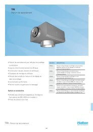
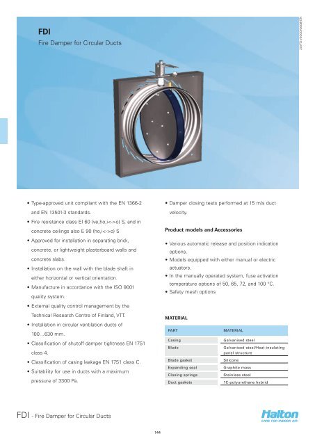
<strong>FDI</strong><br />
<strong>Fire</strong> <strong>Damper</strong> <strong>for</strong> <strong>Circular</strong> <strong>Ducts</strong><br />
20/<strong>FDI</strong>/0000/0608/EN<br />
• Type-approved unit compliant with the EN 1366-2<br />
and EN 13501-3 standards.<br />
• <strong>Fire</strong> resistance class EI 60 (ve,ho,io) S, and in<br />
concrete ceilings also E 90 (ho,io) S<br />
• Approved <strong>for</strong> installation in separating brick,<br />
concrete, or lightweight plasterboard walls and<br />
concrete slabs.<br />
• Installation on the wall with the blade shaft in<br />
either horizontal or vertical orientation.<br />
• Manufacture in accordance with the ISO 9001<br />
quality system.<br />
• External quality control management by the<br />
Technical Research Centre of Finland, VTT.<br />
• Installation in circular ventilation ducts of<br />
100…630 mm.<br />
• Classification of shutoff damper tightness EN 1751<br />
class 4.<br />
• Classification of casing leakage EN 1751 class C.<br />
• Suitability <strong>for</strong> use in ducts with a maximum<br />
pressure of 3300 Pa.<br />
• <strong>Damper</strong> closing tests per<strong>for</strong>med at 15 m/s duct<br />
velocity.<br />
Product models and Accessories<br />
• Various automatic release and position indication<br />
options.<br />
• Models equipped with either manual or electric<br />
actuators.<br />
• In the manually operated system, fuse activation<br />
temperature options of 50, 65, 72, and 100 °C.<br />
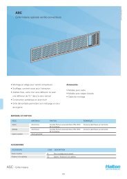
• Safety mesh options<br />
MATERIAL<br />
PART<br />
Casing<br />
Blade<br />
Blade gasket<br />
Expanding seal<br />
Closing springs<br />
Duct gaskets<br />
MATERIAL<br />
Galvanised steel<br />
Galvanised steel/Heat-insulating<br />
panel structure<br />
Silicone<br />
Graphite mass<br />
Stainless steel<br />
1C-polyurethane hybrid<br />
<strong>FDI</strong> - <strong>Fire</strong> <strong>Damper</strong> <strong>for</strong> <strong>Circular</strong> <strong>Ducts</strong><br />
144
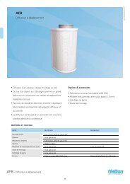
DIMENSIONS<br />
NS ØD L L1 L2 L3<br />
100 99 145 105 40 183<br />
125 124 145 105 40 208<br />
160 159 145 105 40 242<br />
200 199 145 105 40 283<br />
250 249 145 105 40 333<br />
315 314 145 105 40 398<br />
400 399 245 135 110 480<br />
500 499 245 135 110 580<br />
630 629 245 135 110 710<br />
Ø D<br />
D/2+30<br />
L1<br />
L<br />
D/2-30<br />
L2<br />
L3<br />
L3<br />
L3 + 65<br />
20/<strong>FDI</strong>/0000/0608/EN<br />
The size of the installation hole is ØD + 20 mm.<br />
Detailed installation instructions, as well as an<br />
installer’s installation certificate <strong>for</strong>m, are supplied<br />
with each product. See also the section ‘Documents’.<br />
ACCESSORIES AND PRODUCT MODELS<br />
ACCESSORY CODE DESCRIPTION<br />
Mesh on one side N1 galvanised steel<br />
Mesh on both sides N2 galvanised steel<br />
Fuse (manual) FU Thermal release at 50, 65,<br />
72, or 100 ºC<br />
Microswitch MS Closed position indication,<br />
enclosure class IP 65<br />
The manual fire damper can be equipped with a<br />
bipolar microswitch, MS, which indicates the closing<br />
of the shutoff blade. The microswitch has potentialfree<br />
points (no = normally open and nc = normally<br />
closed), which can be used to control other fire<br />
dampers equipped with an electric release, e.g.,<br />
triggering an alarm in the fire suppression system. The<br />
maximum operating voltage and current is 400 V, 10 A.<br />
Actuators<br />
Manual actuator, MA (spring return)<br />
BLF24-T HL, operating voltage AC/DC 24 V (72 ºC,<br />
contains a microswitch), B1<br />
BLF230-T HL, operating voltage AC 230 V (72 ºC,<br />
contains a microswitch), B2<br />
RELEASE TYPES (manual actuator)<br />
The manual fire damper has always a thermal release<br />
operation via a thermal a fuse. Additional release<br />
systems available:<br />
• Solenoid operation, providing a possibility <strong>for</strong><br />
electric signal release<br />
• Electromagnetic release<br />
• Pneumatic release with pressurised gas (e.g., CO2)<br />
Solenoid operation<br />
The manual fire damper can be released using<br />
solenoid, by switching on the solenoid operating<br />
voltage. The release can be initiated by e.g. a smoke<br />
detector, microswitch, pressure switch or similar,<br />
which connects the power supply via e.g. an auxiliary<br />
relay.<br />
Option S1 S2<br />
Operating voltage 24 VDC 230 VAC<br />
Power consumption (design 15 W 40 VA<br />
value)<br />
Enclosure class (minimum) IP20 IP20<br />
Operating Time Ratio ED 100% 100%<br />
<strong>FDI</strong> - <strong>Fire</strong> <strong>Damper</strong> <strong>for</strong> <strong>Circular</strong> <strong>Ducts</strong><br />
145
Electromagnetic operation<br />
The fire damper stays open when the electrical circuit<br />
is closed. The fire damper is shut by opening the<br />
circuit.<br />
Note: Interruption of the power supply closes the<br />
damper. Uninterrupted power supply (e.g., a battery<br />
backup system) is recommended.<br />
Option<br />
EM<br />
Pneumatic release<br />
The manual fire damper can be released by<br />
a pneumatic release, connected to e.g. a fire<br />
suppression system. When the system is activated,<br />
pressure acting on the pneumatic cylinder releases<br />
the spring, closing the fire damper. The actuator is<br />
suitable <strong>for</strong> common pressure levels used in fire<br />
suppression systems. The lowest operating pressure<br />
of the actuator is 200 kPa.<br />
20/<strong>FDI</strong>/0000/0608/EN<br />
Operating voltage<br />
24 VDC<br />
Power consumption (design value)<br />
15 W<br />
Enclosure class (minimum)<br />
IP20<br />
Operating Time Ratio ED 100%<br />
Function<br />
The <strong>FDI</strong> is a circular fire damper, which prevents<br />
fire and smoke from spreading in the ductwork of<br />
ventilation and air conditioning systems.<br />
The <strong>FDI</strong> is approved <strong>for</strong> horizontal and vertical<br />
installation in heavy and light-weight structures<br />
fulfilling the fire resistance class EI 60 (ve,ho,io)<br />
S requirements. It is also approved <strong>for</strong> horizontal<br />
installation in concrete floors/ceilings to fulfill fire<br />
resistance class E 90 (ho,io) S requirements.<br />
The fire damper is equipped with either manual or<br />
electric actuators. All models are equipped with a<br />
thermal fuse and a visual position indicator. The fuse<br />
responds to a rise in temperature, closing the springreturn<br />
blade.<br />
Alternatively, the damper may be released by a<br />
system using an electric actuator or release systems<br />
that are available as accessories to the manual<br />
actuator (solenoid, electromagnetic, or pneumatic).<br />
If the power in the motorised actuator system is<br />
switched off, the blade is automatically closed by a<br />
springreturn actuator.<br />
A double-sealing solution closes the duct, effectively<br />
preventing the spreading of fire gases in the<br />
ventilation ductwork when the fire damper closes. The<br />
flexible seal of the double-sealing system operates<br />
at lower temperatures, while the graphite mass seal<br />
expands to insulate the system at temperatures above<br />
150 ºC.<br />
The nominal release temperature of the fuse with an<br />
electric actuator is 72 °C. Fuses with optional release<br />
temperatures 50, 65, 72 and 100 °C are available <strong>for</strong><br />
the manual actuator.<br />
The fire dampers equipped with electric actuators are<br />
released by switching off the power supply.<br />
The <strong>FDI</strong> fire damper is recommended to be connected<br />
to the MSH <strong>Fire</strong> <strong>Damper</strong> Management System. The<br />
MSH system enables the use of smoke detectors in<br />
ductwork or room spaces. The <strong>FDI</strong> fire damper can<br />
also be connected to other commonly used building<br />
automation systems.<br />
<strong>FDI</strong> - <strong>Fire</strong> <strong>Damper</strong> <strong>for</strong> <strong>Circular</strong> <strong>Ducts</strong><br />
146
Installation<br />
The fire damper is installed on concrete or masonry<br />
walls and ceilings and on lightweight walls.<br />
An opening is always left in the separating element<br />
<strong>for</strong> the casing of the product to be led through the<br />
structure. The maximum diameter of the installation<br />
hole is the fire damper diameter D + 20 mm.<br />
Electric actuator wiring diagram<br />
-<br />
~<br />
+<br />
20/<strong>FDI</strong>/0000/0608/EN<br />
To make installation easier, all products come with an<br />
installation/casting frame, which is used to fasten the<br />
fire damper to the wall surface or the steel frame of<br />
the plasterboard wall.<br />
1 2<br />
S1 S2 S3 S4 S5 S6<br />
< 5 < 80<br />
Tf1 Tf2 Tf3 LED BAE72B-S<br />
The installation is finished by filling the casting frame<br />
from the front of the device with a gypsum-based<br />
firestop mastic that is tested <strong>for</strong> use <strong>for</strong> this purpose<br />
(such as GBG, from Palokatkomiehet Oy; CB 637, from<br />
Hilti; and FIREBREAK COMPOUND, from Würth).<br />
BLF24-T HL<br />
BLF230-T HL<br />
Power supply 24 VAC/VDC, with fuse<br />
72ºC.<br />
Power supply 230 VAC, with fuse<br />
72ºC<br />
During installation, the fire damper and actuator must<br />
Manual actuator wiring diagram (microswitch, MS)<br />
be protected with, e.g., a plastic cover.<br />
The correct operation of the fire damper must be<br />
ensured both be<strong>for</strong>e and after grouting. Setting of the<br />
damper is per<strong>for</strong>med from outside the device.<br />
Detailed installation instructions, as well as an<br />
installer’s installation certificate <strong>for</strong>m, are supplied<br />
with each product. See also the section ‘Documents /<br />
Installation Instructions’.<br />
K1<br />
K1<br />
INSTALLATION OF MODULES<br />
Two fire dampers can be installed using the same<br />
screws on one side such that the lip of the installation<br />
frame of the lower damper is either flattened or<br />
removed, and the casting is spread uninterrupted<br />
from one outside end to the other. See the installation<br />
instructions.<br />
<strong>Fire</strong> damper open<br />
<strong>Fire</strong> damper closed<br />
K1: 13/14 closed K1: 13/14 open<br />
21/22 open 21/22 closed<br />
<strong>FDI</strong> - <strong>Fire</strong> <strong>Damper</strong> <strong>for</strong> <strong>Circular</strong> <strong>Ducts</strong><br />
147
Servicing<br />
A manual fire damper can be reset after the fuse<br />
temperature has fallen below the release temperature.<br />
If the shutoff blade does not lock, the fuse is worn out<br />
and must be replaced. The fuse can be changed from<br />
outside the fire damper.<br />
The fuse of a fire damper equipped with an electric<br />
actuator must be replaced if the fuse has been<br />
released because of a rise in temperature.<br />
To ensure proper operation of fire dampers, they<br />
should be inspected regularly. The minimum<br />
recommended inspection period is one year or<br />
according to the building code It is recommended<br />
that the fire damper is connected to automatic fire<br />
damper management system MSH (operating voltage<br />
24-VAC).<br />
Upon failure during testing of the fire damper,<br />
maintenance service shall be ordered from an<br />
authorised <strong>Halton</strong> representative to ensure appropriate<br />
operation of the product.<br />
Suggested specifications<br />
The technical properties of the type-approved fire<br />
damper shall con<strong>for</strong>m to the EN 1366-2 and EN<br />
135013 standards.<br />
A fire damper of class EI 60 (ve,ho,io) S and in<br />
concrete ceilings also E 90 (ho,io) S, shall have a<br />
double-sealing solution that ensures fire-gas tightness<br />
and fire resistance both at room temperature and in<br />
high temperatures when the fire damper is closed.<br />
In motorised models, the fuse shall be activated at 72<br />
°C.<br />
In the manually operated model, the fuse activation<br />
temperature corresponds to the specifications (50, 65,<br />
72, or 100 °C).<br />
The fuse shall be located inside the damper, and it<br />
shall be possible to replace it from the outside.<br />
The fire damper shall have means <strong>for</strong> external opening<br />
/ triggering of the release and closing.<br />
The fire damper shall include a position indicator.<br />
Where indicated, the manually operated fire damper<br />
shall be supplied with the following release options:<br />
• Electric signal release by closing circuit (initiated<br />
by, e.g., a smoke detector or a microswitch or<br />
pressure switch); the enclosure class of the<br />
electric release arrangement shall be IP54 or better.<br />
• Electromagnetic release by opening circuit.<br />
• Pneumatic release.<br />
20/<strong>FDI</strong>/0000/0608/EN<br />
The fire damper casing complies with the tightness<br />
requirements <strong>for</strong> EN 1751 class C.<br />
The fire damper shall be suitable <strong>for</strong> vertical and<br />
horizontal installation in concrete and masonry walls<br />
and on ceilings and lightweight plasterboard walls<br />
between fire compartments.<br />
The blade shaft can be installed in either horizontal or<br />
vertical orientation, and the actuator can be installed in<br />
any direction.<br />
The fire damper can be installed from the installation<br />
frame side without separate sealing of the installation<br />
opening on the wall.<br />
The internal quality control of the fire damper<br />
manufacturer shall be based on the ISO 9001 quality<br />
system, and the operations of the manufacturer shall<br />
be subject to external third-party quality control.<br />
<strong>FDI</strong> - <strong>Fire</strong> <strong>Damper</strong> <strong>for</strong> <strong>Circular</strong> <strong>Ducts</strong><br />
148
Product code<br />
<strong>FDI</strong>-D<br />
20/<strong>FDI</strong>/0000/0608/EN<br />
D = connection size<br />
100, 125, 160, 200, 250, 315, 400, 500, 630<br />
Specifics and accessories<br />
RE = release type<br />
MA Manual<br />
B1 BLF24-T-2 HL, fuse 72 °C<br />
B2 BLF230-T HL, fuse 72 °C<br />
S1 Solenoid, 24 VDC<br />
S2 Solenoid, 230 VAC<br />
EM Electromagnetic, 24 VDC<br />
PN Pneumatic<br />
FU = fuse release temperature (°C)<br />
72 72 °C<br />
50 50 °C<br />
65 65 °C<br />
100 100 °C<br />
AC = accessories<br />
N1 Safety mesh, 1 side, installed in<br />
actuator side<br />
N2 Safety mesh, 2 sides<br />
MS Microswitch<br />
Code example<br />
<strong>FDI</strong>-160, RE=MA, FU=72<br />
<strong>FDI</strong> - <strong>Fire</strong> <strong>Damper</strong> <strong>for</strong> <strong>Circular</strong> <strong>Ducts</strong><br />
149