IP Subnettin IP Subnetting - International Journal of Electronics ...
IP Subnettin IP Subnetting - International Journal of Electronics ...
IP Subnettin IP Subnetting - International Journal of Electronics ...
You also want an ePaper? Increase the reach of your titles
YUMPU automatically turns print PDFs into web optimized ePapers that Google loves.
<strong>International</strong> <strong>Journal</strong> <strong>of</strong> <strong>Electronics</strong>, Communication & S<strong>of</strong>t Computing Science and Engineering<br />
ISSN: 2277-9477, Volume 2, Issue 5<br />
<strong>IP</strong> <strong>Subnettin</strong>g<br />
Shailesh N. Sisat<br />
Prajkta S. Bhopale<br />
Vishwajit K. Barbudhe<br />
Abstract - Network management becomes more and more<br />
important as computer-networks grow steadily. A critical skill<br />
for any network administrator or security admin that supports<br />
a network environment is <strong>IP</strong> <strong>Subnettin</strong>g. This knowledge can<br />
be gained by different methods and it is needed in different<br />
point <strong>of</strong> views. These individual views arise from distinct needs<br />
<strong>of</strong> persons, who are involved in network management. The<br />
following use cases represent selected groups <strong>of</strong> managers or<br />
engineers. They are not complete, but should increase<br />
comprehension <strong>of</strong> the complexity <strong>of</strong> network discovery. This<br />
paper discusses why subnetting is important, <strong>IP</strong> addressing<br />
basics, decimal to binary conversion and early subnetting.<br />
Keywords: TCP/<strong>IP</strong>, <strong>IP</strong> <strong>Subnettin</strong>g, Class <strong>of</strong> network<br />
I. INTRODUCTION<br />
This article is focusing on the basics <strong>of</strong> <strong>Subnettin</strong>g. While<br />
using <strong>IP</strong> address it is very easy to break it in to subnets so<br />
that the one network address can be used for more than one<br />
networks, The theory called as <strong>Subnettin</strong>g.<br />
<strong>Subnettin</strong>g<br />
allows us to break a large network into a bunch <strong>of</strong> smaller<br />
networks. If an organization is large or if its computers are<br />
geographically dispersed, it makes good sense to divide<br />
network into smaller ones connected together by routers.<br />
<strong>Subnettin</strong>g is important for several reasons.<br />
• Reduced Network Traffic: By subnetting<br />
the network we can partition it to as many smaller networks<br />
as we need and this also helps reduce traffic and hides the<br />
complexity <strong>of</strong> the network.<br />
• Optimized network performance:<br />
Reduced network traffic results in optimized network<br />
performance.<br />
• Simplified management: quickly identify<br />
and resolve network problem in a bunch <strong>of</strong> smaller networks<br />
than within a single big network.<br />
• Security: <strong>Subnettin</strong>g can help ensure<br />
network security by facilitating communication between<br />
computers on the same subnet while preventing access from<br />
computers on other subnets.<br />
• Facilitates spanning <strong>of</strong> large<br />
Geographical distance: Because WAN links are<br />
comparatively slower and more expensive than LAN links, a<br />
single large network that spans long distances can create<br />
problems in every area. Connecting multiple smaller<br />
networks makes the system more efficient.<br />
Introduction to <strong>IP</strong>: Before we start dive into subnetting, we<br />
need to study some basics. The first item for discussion is<br />
the <strong>IP</strong> address. An <strong>IP</strong> address is a numeric identifier<br />
assigned to each machine on an <strong>IP</strong> network. It designates the<br />
5<br />
specific location <strong>of</strong> a device on the network. An <strong>IP</strong> address<br />
is a 32-bit number typically represented in four sections<br />
called octets. These sections are segregated by a dot called<br />
as dotted decimal representation. A sample <strong>IP</strong> address is<br />
172.16.10.15. This <strong>IP</strong> address is what identifies a system or<br />
resource on a particular <strong>IP</strong> network. The <strong>IP</strong> address itself is<br />
actually made up <strong>of</strong> two parts. One part identifies the<br />
network that the host belongs to, and the other part identifies<br />
the host. To figure out where<br />
the network portion stops and the host part begins you need<br />
a subnet mask. A subnet mask is also represented in dotted<br />
decimal notation. When you see an <strong>IP</strong> address, you will<br />
always see another number associated with the <strong>IP</strong> address<br />
that looks something like one <strong>of</strong> the following:<br />
• 255.0.0.0<br />
• 255.255.0.0<br />
• 255.255.255.0<br />
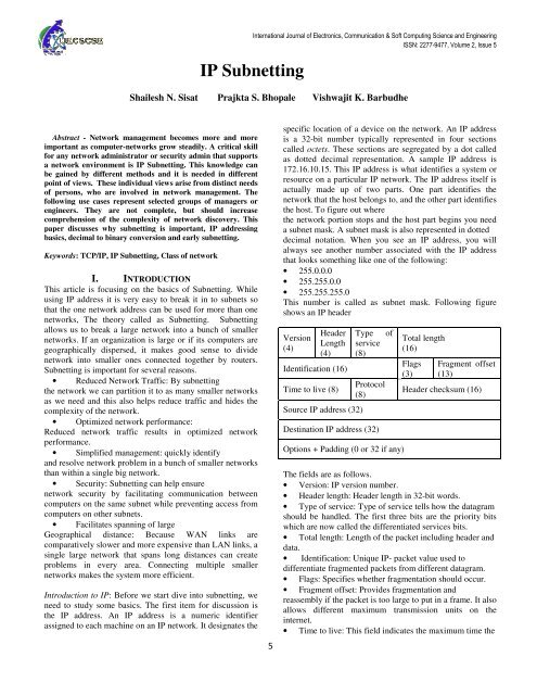
This number is called as subnet mask. Following figure<br />
shows an <strong>IP</strong> header<br />
Version<br />
(4)<br />
Header<br />
Length<br />
(4)<br />
Identification (16)<br />
Time to live (8)<br />
Source <strong>IP</strong> address (32)<br />
Type <strong>of</strong><br />
service<br />
(8)<br />
Protocol<br />
(8)<br />
Destination <strong>IP</strong> address (32)<br />
Options + Padding (0 or 32 if any)<br />
Total length<br />
(16)<br />
Flags<br />
(3)<br />
Fragment <strong>of</strong>fset<br />
(13)<br />
Header checksum (16)<br />
The fields are as follows.<br />
• Version: <strong>IP</strong> version number.<br />
• Header length: Header length in 32-bit words.<br />
• Type <strong>of</strong> service: Type <strong>of</strong> service tells how the datagram<br />
should be handled. The first three bits are the priority bits<br />
which are now called the differentiated services bits.<br />
• Total length: Length <strong>of</strong> the packet including header and<br />
data.<br />
• Identification: Unique <strong>IP</strong>- packet value used to<br />
differentiate fragmented packets from different datagram.<br />
• Flags: Specifies whether fragmentation should occur.<br />
• Fragment <strong>of</strong>fset: Provides fragmentation and<br />
reassembly if the packet is too large to put in a frame. It also<br />
allows different maximum transmission units on the<br />
internet.<br />
• Time to live: This field indicates the maximum time the
<strong>International</strong> <strong>Journal</strong> <strong>of</strong> <strong>Electronics</strong>, Communication & S<strong>of</strong>t Computing Science and Engineering<br />
ISSN: 2277-9477, Volume 2, Issue 5<br />
datagram is allowed to remain in the internet system. If this<br />
field contains the value zero, then the datagram must be<br />
destroyed. This field is modified in internet header<br />
processing. The time is measured in units <strong>of</strong> seconds, but<br />
since every module that processes a datagram must decrease<br />
the TTL by at least one even if it process the datagram in<br />
less than a second, the TTL must be thought <strong>of</strong> only as an<br />
upper bound on the time a datagram may exist.<br />
The<br />
intention is to cause undeliverable datagrams to be<br />
discarded, and to bound the maximum datagram lifetime.<br />
• Protocol: In the Internet Protocol version 4 (<strong>IP</strong>v4)<br />
[RFC791] there is a field called "Protocol" to identify the<br />
next level protocol. This is an 8 bit field. In Internet<br />
Protocol version 6 (<strong>IP</strong>v6) [RFC2460], this field is called the<br />
"Next Header" field.<br />
• Header checksum: Cyclic redundancy check (CRC) on<br />
header only.<br />
• Source <strong>IP</strong> address: 32-bit <strong>IP</strong> address <strong>of</strong> sending station.<br />
• Destination <strong>IP</strong> address: 32-bit <strong>IP</strong> address <strong>of</strong> the station<br />
this packet is destined for.<br />
• Options: Used for network testing, debugging, security.<br />
Encodes the options requested by the sending user.<br />
II.<br />
DECIMAL AND BINARY<br />
In <strong>IP</strong> subnetting, it is important that we know how to<br />
convert <strong>IP</strong> addresses and subnet masks from their decimal<br />
form to the binary form because the locations <strong>of</strong> the 1s and<br />
0s is extremely important.<br />
If we use the sample <strong>IP</strong> address from before, 172.16.10.15,<br />
and represent it in binary format, it would look like this:<br />
10101100.00010000.000001010.00001111. So, how do we<br />
get from the decimal form to the binary form, and vice<br />
versa?<br />
First, let’s convert from binary to decimal. If we take the<br />
first octet <strong>of</strong> our sample <strong>IP</strong> address and map it to the binary<br />
numbering system, it looks like this:<br />
Binary 2 7<br />
<strong>IP</strong><br />
address<br />
=128<br />
2 6<br />
=64<br />
2 5<br />
=32<br />
2 4<br />
=16<br />
1 0 1 0 1<br />
2 3<br />
=8<br />
2 2<br />
=4<br />
2 1<br />
=2<br />
1 0 0<br />
2 0<br />
=1<br />
Now all we have to do is add the decimal numbers together<br />
where a 1 appears and we will get the decimal equivalent <strong>of</strong><br />
the binary number. In this case it looks like this:<br />
128 + 32 + 8 + 4 = 172.<br />
Now let’s convert from binary to decimal. let’s take our 172<br />
example from previously. The formula for conversion is as<br />
follows.<br />
1. First divide the number by 2. The remainder will be either<br />
0 or 1.<br />
2. Write down the remainder.<br />
3. Divide the remaining number without the remainder by 2.<br />
Again, the remainder will be either 1 or 0.<br />
4. Write down the remainder to the left <strong>of</strong> the previous<br />
remainder.<br />
5. Repeat this until you end up with 0.<br />
For 172, the formula would look like this:<br />
172 ÷ 2 = 86 remainder 0<br />
86 ÷ 2 = 43 remainder 0<br />
43 ÷ 2 = 21 remainder 1<br />
21 ÷ 2 = 10 remainder 1<br />
10 ÷ 2 = 5 remainder 0<br />
5 ÷ 2 = 2 remainder 1<br />
2 ÷ 2 = 1 remainder 0<br />
1 ÷ 2 = 0 remainder 1<br />
So binary number for 172 = 10101100.<br />
Each section <strong>of</strong> an <strong>IP</strong> address is 8 bits long. In the previous<br />
example, the conversion worked out to 8 bits exactly, so that<br />
was easy. If we used a smaller number such as 12, we would<br />
have reached 0 before we had 8 bits. If this occurs, fill in the<br />
remaining bits with 0s. For example:<br />
12 ÷ 2 = 6 remainder 0<br />
6 ÷ 2 = 3 remainder 0<br />
3 ÷ 2 = 1 remainder 1<br />
1 ÷ 2 = 0 remainder 1<br />
Because we got to 0 in only four steps, the remaining bits<br />
are 0---so the binary <strong>of</strong> 12 is 00001100.<br />
III. <strong>IP</strong> TERMINOLOGY<br />
• Network address: This is the designation used in<br />
routing to send packets to a remote network. for example,<br />
10.0.0.0,172.16.0.0 and 192.168.0.0<br />
• Broadcast address: The address used by applications<br />
and hosts to send information to all nodes on a network is<br />
called the broadcast address. Example include<br />
255.255.255.255, which is any network, all nodes;<br />
172.16.255.255, which is all subnets and hosts on network<br />
172.16.0.0; and 10.255.255.255, which broadcasts to all<br />
subnets and hosts on network10.0.0.0<br />
• Class <strong>of</strong> network: The designer <strong>of</strong> the Internet decided<br />
to create classes <strong>of</strong> network based on network size, for the<br />
small number <strong>of</strong> networks possessing a very large number<br />
<strong>of</strong> nodes, they created the rank Class A network. At the<br />
other extreme is the Class C network, which is reserved for<br />
the numerous networks with a small number <strong>of</strong> nodes. The<br />
class distinction for networks between very large and very<br />
small is predictably called the Class B network.<br />
Subdividing an <strong>IP</strong> address into a network and<br />
node address is determined by the class designation <strong>of</strong> one’s<br />
network. Following fig summarizes the three classes <strong>of</strong><br />
networks.<br />
8bits 8bits 8bits 8bits<br />
Class A: Network Host Host Host<br />
Class B: Network Network Host Host<br />
Class C: Network Network Network Host<br />
6
<strong>International</strong> <strong>Journal</strong> <strong>of</strong> <strong>Electronics</strong>, Communication & S<strong>of</strong>t Computing Science and Engineering<br />
ISSN: 2277-9477, Volume 2, Issue 5<br />
Class D:<br />
Class E:<br />
Multicast<br />
Research<br />
The determination <strong>of</strong> which class a particular network fell in<br />
was determined by the first octet <strong>of</strong> the <strong>IP</strong> address,<br />
specifically by the first few bits <strong>of</strong> the first octet. This is<br />
represented in the following table.<br />
First Bits<br />
1 st Octet Number <strong>of</strong> Hosts per<br />
networks network<br />
Class A 0 1-126 126 16,777,214<br />
Class B 10 128-191 16,384 65,534<br />
Class C 110 192-223 2,097,152 254<br />
Class D 1110 224-239 n/a n/a<br />
Class E 11110 240-254 n/a n/a<br />
The network ID cannot be 127. The 127.0.0.0 network is<br />
reserved for loop-back and was originally designed for<br />
testing purposes. Class D and E are special classes; in this<br />
article discussion is focus on Classes A, B, and C. Each <strong>of</strong><br />
these classes has a default subnet mask and a private address<br />
range.<br />
Private Addresses: The address can be public (i.e., unique)<br />
or private. In today’s enterprise networks, private addressing<br />
is commonly used because <strong>of</strong> the address shortage in <strong>IP</strong>v4.<br />
In enterprise networks private addressing is preferred<br />
because it provides secure access rather than open and<br />
public access to the enterprise network. The private address<br />
ranges are utilized on internal networks, and addresses in<br />
these ranges cannot be routed in the public network <strong>of</strong> the<br />
Internet. These defaults and private ranges are shown here:<br />
Class<br />
Default Subnet<br />
Mask<br />
Private Address Range<br />
Class A 255.0.0.0 10.0.0.0 - 10.255.255.255<br />
Class B 255.255.0.0 172.16.0.0 - 172.31.255.255<br />
Class C 255.255.255.0 192.168.0.0 - 192.168.255.255<br />
<strong>Subnettin</strong>g the network: A large network is divided into a<br />
smaller network the process is known as <strong>Subnettin</strong>g and the<br />
smaller network is known as subnetwork or subnet.<br />
To create subnetworks, take bits from the host portion <strong>of</strong> the<br />
<strong>IP</strong> address and reserve them to define the subnet address.<br />
This means fewer bits for hosts, so the more subnets, the<br />
fewer bits available for defining hosts.<br />
Class<br />
A<br />
B<br />
C<br />
Format<br />
Default Subnet<br />
Mask<br />
network.node.node.node 255.0.0.0<br />
network.networ.node.node.node 255.255.0.0<br />
network.networ.network.node<br />
255.255.255.0<br />
Classless Inter Domain Routing (CIDR):<br />
CIDR is the method that ISP (Internet service providers) use<br />
to allocate a number <strong>of</strong> addresses to a company or a<br />
customer. ISP provide addresses in a certain block size. for<br />
example 192.168.10.32/28. We may identify the subnet<br />
mask from this block size. The slash notation (/) means how<br />
many bits out <strong>of</strong> 32 bits are turned on (1s).<br />
for example , a Class C default mask would be<br />
255.255.255.0, which is /24 because 24 bits are ones (1s),<br />
11111111.11111111.11111111.0<br />
Following table shows every available subnet mask and its<br />
equivalent CIDR slash notation.<br />
Subnet Mask CIDR Subnet Mask<br />
CIDR<br />
Value<br />
Value<br />
255.0.0.0 /8 255.255.240.0 /20<br />
255.128.0.0 /9 255.255.248.0 /21<br />
255.192.0.0 /10 255.255.252.0 /22<br />
255.224.0.0 /11 255.255.254.0 /23<br />
255.240.0.0 /12 255.255.255.0 /24<br />
255.248.0.0 /13 255.255.255.128 /25<br />
255.252.0.0 /14 255.255.255.192 /26<br />
255.254.0.0 /15 255.255.255.224 /27<br />
255.255.0.0 /16 255.255.255.240 /28<br />
255.255.128.0 /17 255.255.255.248 /29<br />
255.255.192.0 /18 255.255.255.252 /30<br />
255.255.224.0 /19<br />
The largest mask available (regardless <strong>of</strong> the class <strong>of</strong><br />
address) can only be a /30 because at least 2 bits for host<br />
bits are required.<br />
The /8 through /15 can only be used with Class A network<br />
addresses. /16 through /23 can be used by Class A and B<br />
network addresses. /24 through /30 can be used by Class A,<br />
B, and C network addresses.<br />
Hosts and routers use Boolean math to determine the netid<br />
and the hostid and the hosted by the use <strong>of</strong> ANDing.<br />
Subnet Mask: In order to reduce the conjunction, network is<br />
logically break into pieces. Netmask is mechanisum, we<br />
have to use it to identify the range <strong>of</strong> <strong>IP</strong> to create a<br />
network.A subnet mask is a 32 bit value that allows the<br />
recipient <strong>of</strong> <strong>IP</strong> packets to distinguish the network ID portion<br />
<strong>of</strong> the <strong>IP</strong> address from the host ID portion <strong>of</strong> the <strong>IP</strong> address.<br />
Following table shows the default subnet masks for class A,<br />
B and C.<br />
7<br />
Bit1 Bit2<br />
0 0<br />
0 1<br />
1 0<br />
1 1<br />
Result<br />
0<br />
0<br />
0<br />
1
<strong>International</strong> <strong>Journal</strong> <strong>of</strong> <strong>Electronics</strong>, Communication & S<strong>of</strong>t Computing Science and Engineering<br />
ISSN: 2277-9477, Volume 2, Issue 5<br />
Simple steps in <strong>Subnettin</strong>g:<br />
Identify Class <strong>of</strong> network<br />
Default Net mask<br />
(number <strong>of</strong> stolen bits)<br />
• Number <strong>of</strong> networks = 2 (available bit – stolen<br />
• Number <strong>of</strong> hosts per network= 2 bit) – 2<br />
<strong>Subnettin</strong>g a Class C address:<br />
Example: Network address = 192.168.10.0<br />
Subnet mask = 255.255.255.192<br />
<br />
<br />
1 st step: identify class <strong>of</strong> network<br />
It’s a Class C network<br />
2 nd step: Default subnet mask<br />
255.255.255.0<br />
Subnet mask = 255.255.255.240<br />
what is the subnet and broadcast address <strong>of</strong> the network <strong>of</strong><br />
which the above address is a member?<br />
<br />
<br />
1 st step: identify class <strong>of</strong> network<br />
It’s a Class C network<br />
2 nd step: Default subnet mask<br />
255.255.255.0<br />
128 64 32 16<br />
49 0 0 1 1<br />
240 1 1 1 1<br />
49=32+16+1<br />
240=128+64+32+16<br />
8 4 2 1<br />
0 0 0 1<br />
0 0 0 0<br />
192=128+64<br />
0 0 1 1<br />
0 0 0 0<br />
128 64 32 16 8 4 2 1<br />
0 0 0 0 0 0 0 0 0<br />
192 1 1 0 0 0 0 0 0<br />
0 0 0 0 0 0 0 0<br />
Result <strong>of</strong> above AND operation is zero (0) hence the first <strong>IP</strong><br />
address is 192.168.10.0<br />
<br />
<br />
3 rd step: Number <strong>of</strong> subnetworks = 2<br />
2 2 = 4 subnets<br />
4 th step:<br />
Number <strong>of</strong> hosts per subnetwork= 2<br />
2<br />
= 2 (8-2) -2<br />
= 62 hosts<br />
(number <strong>of</strong> stolen bits)<br />
(available bit – stolen bit) –<br />
a) 192.168.10.0 1 st subnet <strong>IP</strong><br />
b) 192.168.10.1 1 st valid host <strong>IP</strong><br />
c) 192.168.10.62 last valid host<br />
d) 192.168.10.63 broadcast <strong>IP</strong><br />
Similarly the following table shows the all possible subnets,<br />
the valid host ranges <strong>of</strong> each, and the broadcast address <strong>of</strong><br />
each subnet.<br />
subnet <strong>IP</strong> x.x.x.0 x.x.x.64 x.x.x.128 x.x.x.192<br />
1 st valid host x.x.x.1 x.x.x.65 x.x.x.129 x.x.x.193<br />
<strong>IP</strong><br />
last valid x.x.x.62 x.x.x.126 x.x.x.190 x.x.x.254<br />
host<br />
Broadcast <strong>IP</strong> x.x.x.63 x.x.x.127 x.x.x.191 x.x.x.255<br />
Example: Network address = 192.168.10.49<br />
8<br />
32+16=48<br />
Result <strong>of</strong> above AND operation is zero 48 hence the first <strong>IP</strong><br />
address is 192.168.10.48<br />
3 rd step: Number <strong>of</strong> subnetworks = 2 <br />
2 4 = 16 subnets<br />
4 th step:<br />
Number <strong>of</strong> hosts per network= 2 (available bit – stolen bit) – 2<br />
= 2 (8-4) -2<br />
= 14 hosts<br />
Now we know the possible subnets are 16. Now keep<br />
adding 16 until we pass the host address 49, starting from<br />
zero.0, 16,32,48,64, and so on. The host address <strong>of</strong> 49 is<br />
between 48 and 64 so the subnet is 48.<br />
a) 192.168.10.48 1 st subnet <strong>IP</strong><br />
b) 192.168.10.49 1 st valid host <strong>IP</strong><br />
c) 192.168.10.62 last valid host<br />
d) 192.168.10.63 broadcast <strong>IP</strong><br />
<strong>Subnettin</strong>g a Class B address:<br />
Example: Network address = 172.16.0.0<br />
Subnet mask = 255.255.128.0<br />
1 st step: identify class <strong>of</strong> network<br />
It’s a Class B network<br />
2 nd step: Default subnet mask<br />
255.255.0.0<br />
128<br />
(number <strong>of</strong> stolen bits)
<strong>International</strong> <strong>Journal</strong> <strong>of</strong> <strong>Electronics</strong>, Communication & S<strong>of</strong>t Computing Science and Engineering<br />
ISSN: 2277-9477, Volume 2, Issue 5<br />
128 64 32 16 8 4 2 1<br />
0 0 0 0 0 0 0 0 0<br />
128 1 0 0 0 0 0 0 0<br />
0 0 0 0 0 0 0 0<br />
Result <strong>of</strong> above AND operation is zero (0) hence the first <strong>IP</strong><br />
address is 172.16.0.0<br />
<br />
<br />
3 rd step: Number <strong>of</strong> subnetworks = 2<br />
(number <strong>of</strong> stolen bits)<br />
2 1 = 2 subnets<br />
4 th step:<br />
(available bit – stolen<br />
Number <strong>of</strong> hosts per network= 2 bit) – 2<br />
AUTHOR’S PROFILE<br />
Shailesh N. Sisat is a master degree candidate in <strong>Electronics</strong> &<br />
Telecommunication Engineering <strong>of</strong> SGB Amravati University,<br />
Maharashtra, India. . He received his B.E. degree in <strong>Electronics</strong> &<br />
Telecommunication Engineering from SGB Amravati University. He is<br />
Red Hat Certified Engineer having industrial experience in networking<br />
industry<br />
Prajkta S. Bhopale is a master degree candidate in <strong>Electronics</strong> &<br />
Telecommunication Engineering <strong>of</strong> SGB Amravati University Maharashtra,<br />
India. She received her B.E. degree in <strong>Electronics</strong> & Telecommunication<br />
Engineering from SGB Amravati University.<br />
Vishwajit K. Barbudhe is a pr<strong>of</strong>essor in the Department <strong>of</strong><br />
<strong>Electronics</strong> & Telecommunication Engineering, Agnihotri C.O.E. Wardha,<br />
Nagpur University, Maharashtra, India. . He received his M.Tech degree in<br />
<strong>Electronics</strong> & communication Engineering from PIT C.O.E. RGPV<br />
University, MP, India. He received his B.E. degree in <strong>Electronics</strong> &<br />
Telecommunication Engineering from SGB Amravati University.<br />
In this case, available bits are addition <strong>of</strong> third and<br />
fourth octet.<br />
= 2 (16-1) -2<br />
= 32,766 hosts<br />
subnet <strong>IP</strong> 172.16.0.0 172.16.128.0<br />
1 st valid host <strong>IP</strong> 172.16.0.1 172.16.128.1<br />
last valid host 172.16.127.254 172.16.255.254<br />
Broadcast <strong>IP</strong> 172.16.127.255 172.16.255.255<br />
CONCLUSION<br />
This article has discussed <strong>IP</strong> <strong>Subnettin</strong>g as it is an important<br />
skill to acquire because it <strong>of</strong>fers many benefits in any<br />
networked environment. Using the information in this paper,<br />
you should be able to subnet any network to take full<br />
advantage <strong>of</strong> the <strong>IP</strong> address space you utilize.<br />
REFERENCES<br />
[1]Y. Rekhter et al., “Address Allocation for Private Intranets,” IETF RFC<br />
1918, Feb. 1996.<br />
[2] BEHCET SARIKAYA, “Home agent placement and <strong>IP</strong> address<br />
management for integrating WLANS with cellular networks” 1536-<br />
1284/06/$20.00 © 2006 IEEE<br />
[3] G. Montenegro, “Reverse Tunneling for Mobile <strong>IP</strong>,” IETF RFC 3024,<br />
Jan. 2001.<br />
[4] S. Vaarala et al., , “Mobile <strong>IP</strong>v4 Traversal Across <strong>IP</strong>Sec based VPN<br />
Gateways,” Internet draft, Nov. 2005; http://ietfreport.isoc.org/all-ids/draftietf-mip4-vpn-prob<br />
lem-solution-02.txt<br />
[5] Bolt Beranek and Newman, "Specification for the Interconnection <strong>of</strong> a<br />
Host and an IMP," BBN Technical Report 1822, Revised May 1978.<br />
[6] Shoch, J., "Inter-Network Naming, Addressing, and Routing,"<br />
COMPCON, IEEE Computer Society, Fall 1978.<br />
[7] Postel, J., "Address Mappings," RFC 796, , USC/Information Sciences<br />
Institute, September 1981.<br />
[8] Shoch, J., "Packet Fragmentation in Inter-Network Protocols,"<br />
Computer Networks, v. 3, n. 1, February 1979.<br />
9


