

analiza naprezanja u ucvršcenju polova rotora generatora s ...
analiza naprezanja u ucvršcenju polova rotora generatora s ...
analiza naprezanja u ucvršcenju polova rotora generatora s ...

You also want an ePaper? Increase the reach of your titles
YUMPU automatically turns print PDFs into web optimized ePapers that Google loves.
Ma{instvo 2(7), 63 – 74, (2003)<br />
N.[virig;....: ANALIZA NAPREZANJA U U^VR[^ENJU...<br />
4. ISPITIVANJE MODELA<br />
4.1 Optere}ivanje modela<br />
Kona~no obra|en model spreman je da se optereti<br />
i da se izvr{e sva potrebna mjerenja. Polo`aj<br />
to~aka na modelu odre|en je pravokutnim<br />
koordinatama ~ija se jedna os poklapa sa osi<br />
simetrije modela. Urezivanje koordinatnih osi u<br />
povr{inu modela nije mogu}e zbog pojave<br />
unutra{njih <strong>naprezanja</strong> na modelu, koja bi imala<br />
negativnu posljedicu na ispitivanje.<br />
Optere}ivanje svih modela izvr{eno je u zatvorenom<br />
okvirnom nosa~u pomo}u vijka sa trapeznim<br />
navojem.<br />
Prijenos sile na modelima izveden je pomo}u<br />
posebnih ~eljusti koje se sa vijcima pri~vrste na<br />
model, a na drugoj strani ~eljusti nalazi se<br />
simetri~no izbu{ena rupa koja se spaja s<br />
prstenastim dinamometrom pomo}u zatika.<br />
Same ~eljusti su postavljene tako da budu<br />
simetri~ne sa modelom i da se sila prenosi<br />
podjednako na sve rupe modela<br />
Svi modeli optere}ivani su u dva me|usobno<br />
okomita smjera kako bi se {to vjernije simuliralo<br />
stvarno stanje <strong>naprezanja</strong> na mjestu u~vr{}enja<br />
pola.<br />
Omjer vertikalne i horizontalne sile kojom se<br />
optere}uje model odabran je tako kod svih<br />
modela, da se dobije odnos <strong>naprezanja</strong> koji<br />
odgovara stvarnom stanju <strong>naprezanja</strong> u realnim<br />
pogonskim uvjetima.<br />
Iznosi sila F V i F H kojima su optere}ivani modeli<br />
dani su u tablici 4.1. Odabran je uvijek onaj omjer<br />
sila F V / F H koji je za razmatranje pojava u modelu<br />
najpogodniji tj. za taj omjer u modelima se<br />
pojavljuje maksimalni red izokroma. Taj se red<br />
izokroma najlak{e snima u kriti~nom presjeku,<br />
budu}i bi se kod ve}ih iznosa optere}enja<br />
maksimalni red izokroma znatno pove}ao, te bi one<br />
postale toliko guste i nejasne da se ne bi mogle<br />
vi{e razlu~ivati (brojati).<br />
4. TESTING OF THE MODEL<br />
4.1. Loading of the model<br />
When the model is finished it is ready to be loaded<br />
and submitted to all the necessary measurements.<br />
The position of points on the model is defined by<br />
rectangular coordinates. One of their axes agrees<br />
with the model symmetry axes. Cutting in axis<br />
coordinates into the model surface is not possible<br />
because inner stresses occur in the model, which<br />
would have a negative effect on testing.<br />
The loading of all models was carried out in a<br />
closed frame carrier by means of trapeze thread<br />
screw.<br />
The transmission of force on models was carried<br />
out by means of special jaws fixed by screws to<br />
the model. On the other side of the jaw there is a<br />
symmetrically drilled hole which is connected to<br />
the ring dynamometer by means of a pin.<br />
The jaws are symmetrical with the model and the<br />
force is transmitted equally to all holes of the model.<br />
All the models are loaded in two vertical<br />
directions. In that way the simulation of the real<br />
stress on the spot where the pole is fixed is very<br />
reliable.<br />
The ratio between the vertical and horizontal force<br />
by which the model is loaded is chosen for all<br />
models, i.e. the stress ratio (σ v / σ h ) = 1, which<br />
corresponds to the real arrangement of the<br />
generator pole fixing.<br />
Values of the forces F V and F H by which the model<br />
was loaded can be seen in Table 4.1. The force<br />
ratio, F V and F H was chosen so that it would give<br />
the most convenient way of considering the<br />
phenomena in the model, i.e. for that ratio the<br />
maximum order of isochrome appears in the<br />
models. This isochrome order is recorded easily in<br />
the critical cross-section, since at higher loading the<br />
number of maximum isochrome order is increased<br />
considerably. They become so dense and unclear<br />
that they cannot be distinguished (counted).<br />
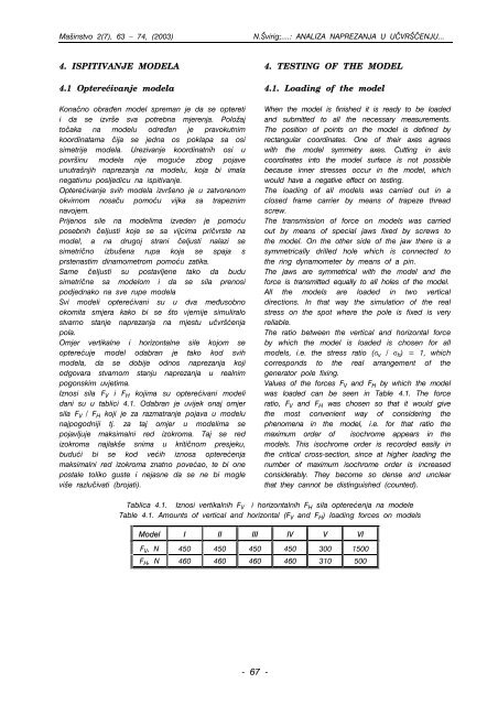
Tablica 4.1. Iznosi vertikalnih F V i horizontalnih F H sila optere}enja na modele<br />
Table 4.1. Amounts of vertical and horizontal (F V and F H ) loading forces on models<br />
Model I II III IV V VI<br />
F V , N 450 450 450 450 300 1500<br />
F H , N 460 460 460 460 310 500<br />
- 67 -


![zavarivanje kao metod produ@enja @ivotnog vijeka ku]i[ta toplotnih ...](https://img.yumpu.com/36506092/1/184x260/zavarivanje-kao-metod-produenja-ivotnog-vijeka-kuita-toplotnih-.jpg?quality=85)