Autodesk Simulation Product Brochure - Ad-Tech Inc
Autodesk Simulation Product Brochure - Ad-Tech Inc
Autodesk Simulation Product Brochure - Ad-Tech Inc

Create successful ePaper yourself
Turn your PDF publications into a flip-book with our unique Google optimized e-Paper software.
<strong>Autodesk</strong>®<br />
<strong>Simulation</strong><br />
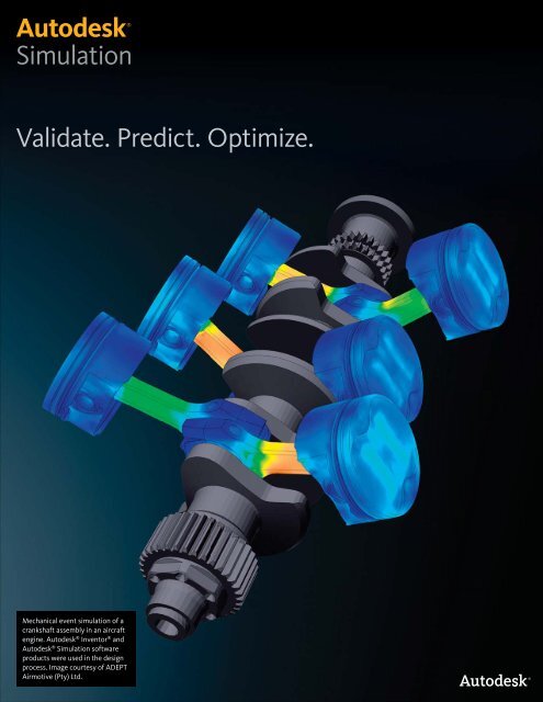
Validate. Predict. Optimize.<br />
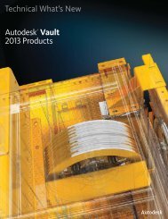
Mechanical event simulation of a<br />
crankshaft assembly in an aircraft<br />
engine. <strong>Autodesk</strong> ® Inventor ® and<br />
<strong>Autodesk</strong> ® <strong>Simulation</strong> software<br />
products were used in the design<br />
process. Image courtesy of ADEPT<br />
Airmotive (Pty) Ltd.
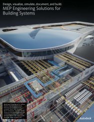
Design Validation and Optimization<br />
Physical prototypes are costly. Optimizing designs and<br />
eliminating errors before manufacturing helps increase<br />
efficiency, productivity, and innovation.<br />
Facing these issues?<br />
<br />
accurate design decisions without building<br />
multiple physical prototypes.<br />
<br />
before investing resources in design<br />
changes or new products.<br />
<br />
materials—not just common metals.<br />
<br />
multiple physical effects are critical design<br />
considerations.<br />
<br />
simulation toolkit without retraining the<br />
design team.<br />
<br />
simulation on geometry from multiple CAD<br />
software tools.<br />
The <strong>Autodesk</strong> ® <strong>Simulation</strong> (formerly <strong>Autodesk</strong> ®<br />
Algor ® <strong>Simulation</strong>) product line, part of the<br />
<strong>Autodesk</strong> ® solution for Digital Prototyping,<br />
provides a broad range of simulation tools that<br />
enable designers and engineers to bring product<br />
performance knowledge into early stages of the<br />
design cycle—helping to improve collaboration,<br />
design better and safer products, save time, and<br />
reduce manufacturing costs.<br />
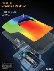
Perform Accurate <strong>Simulation</strong>s Efficiently<br />
<strong>Simulation</strong> enables critical engineering decisions<br />
to be made earlier in the design process. With<br />
<strong>Autodesk</strong> <strong>Simulation</strong> software, designers and<br />
engineers have the tools to more easily study initial<br />
design intent and help predict the performance of a<br />
complete digital prototype.<br />
When working with CAD geometry, automatic<br />
meshing tools produce high-quality elements on the<br />
first pass—resulting in higher simulation accuracy<br />
within the areas of greatest engineering concern<br />
and helping to predict product performance in<br />
less time. Built-in modeling capabilities enable<br />
designers and engineers to directly edit the mesh<br />
to help with accurate placement of loads and<br />
constraints, or create simplified geometry for<br />
proof-of-concept studies. In addition to increasing<br />
productivity through modeling flexibility, <strong>Autodesk</strong><br />
<strong>Simulation</strong> software makes it possible to quickly<br />
validate design concepts before resources are<br />
invested in significant design changes or new<br />
products.<br />
Help predict product<br />
performance with<br />
<strong>Autodesk</strong> <strong>Simulation</strong><br />
software.
Choose the Right Materials<br />
Support for a wide range of linear and nonlinear<br />
materials allows for better understanding of the<br />
real-world behavior of products. No matter which<br />
materials are included in a design, from metal to<br />
rubber, material data is vital to the accuracy of an<br />
engineering simulation—it allows designers and<br />
engineers to learn more about how a product will<br />
perform or even how it might fail.<br />
Expand the Engineering <strong>Simulation</strong> Toolkit Easily<br />
Decisions to further integrate engineering<br />
simulation into the design process often lead<br />
to unexpected costs and delays associated with<br />
retraining the product design team. By providing<br />
an entire range of validation and optimization<br />
tools within one easy-to-use interface, <strong>Autodesk</strong><br />
<strong>Simulation</strong> software lets designers and engineers<br />
start with mainstream tools and then expand<br />
their toolkit to include more advanced simulation<br />
such as mechanical event simulation (MES) and<br />
computational fluid dynamics (CFD)—without the<br />
need to learn new workflows.<br />
Combine Multiple Physical Effects in<br />
<strong>Ad</strong>vanced <strong>Simulation</strong>s<br />
Real-world product behavior is often the result of<br />
multiple physical effects interacting simultaneously.<br />
<strong>Ad</strong>vanced simulation setup is made easier through<br />
the use of standard engineering terminology, visual<br />
process guidance, and user-friendly tools and<br />
wizards that automate the transfer of simulation<br />
results among multiple analyses—helping designers<br />
and engineers focus on product performance, not<br />
advanced numerical or simulation methods.<br />
Collaborate in a Multi-CAD Environment<br />
Manufacturers often create and share designs in<br />
multiple CAD software tools, making it difficult<br />
to integrate engineering simulation tools into an<br />
existing design process without significant and<br />
costly changes. <strong>Autodesk</strong> <strong>Simulation</strong> software<br />
supports efficient workflows in today’s multi-<br />
CAD environment by providing direct geometry<br />
exchange and full associativity with <strong>Autodesk</strong> ®<br />
Inventor ® , Pro/ENGINEER ® , Solid Edge ® ,<br />
SolidWorks ® , and other software.<br />
Simulate More and Build Fewer<br />
Physical Prototypes<br />
Necessary design changes become more apparent<br />
when a product’s real-world environment is fully<br />
simulated, but computationally intensive analyses<br />
can also be time and resource intensive. Fast<br />
solvers in <strong>Autodesk</strong> <strong>Simulation</strong> software utilize<br />
the power of all available computing resources<br />
to perform parallel and distributed processing,<br />
allowing designers and engineers to study more<br />
realistic digital prototypes in less time.<br />
Learn More About Your <strong>Product</strong>’s Performance<br />
Through easy-to-use tools, extensive CAD<br />
support, and proven technology, <strong>Autodesk</strong><br />
<strong>Simulation</strong> software helps you predict the realworld<br />
performance of products while reducing<br />
reliance on physical prototypes. Design validation<br />
and optimization through extensive engineering<br />
simulation helps you bring better products to<br />
market faster and at less cost.
Modeling and Meshing<br />
Create finite element models and meshes using tools and<br />
wizards designed to improve productivity and simulation<br />
accuracy.<br />
<strong>Autodesk</strong> <strong>Simulation</strong><br />
software includes tools<br />
for creating finite element<br />
models and meshes,<br />
including solid models,<br />
thin-walled models,<br />
surface models, and line<br />
element models. Wizards<br />
automate finite element<br />
modeling and meshing<br />
tasks, boosting your<br />
productivity.<br />
CAD Data Exchange<br />
Make iterative design changes without redefining<br />
materials, loads, constraints, or other simulation<br />
data by working with the native CAD format,<br />
exchanging geometry and related data directly<br />
with <strong>Autodesk</strong> Inventor software and most CAD<br />
solid modelers.<br />
Import 2D and 3D geometry through CAD<br />
universal file formats such as ACIS ® , IGES, STEP,<br />
and STL for solid models and CDL, DXF, and IGES<br />
for wireframe models.<br />
Model Simplification<br />
Simplify your CAD model by suppressing features<br />
in preparation for simulation.<br />
Reduce part geometry to minimize processing<br />
time.<br />
CAD Solid Models<br />
Mesh CAD solid models to represent the physical<br />
volume of parts.<br />
Work with the same CAD models used throughout<br />
the design process, opening geometry and related<br />
data directly in <strong>Autodesk</strong> <strong>Simulation</strong> software.<br />
CAD Surface Models<br />
Build surface models in CAD software and<br />
automatically mesh using unstructured 3D<br />
quadrilateral or triangular elements and<br />
refinement.<br />
Reduce thin-walled geometry in a solid model to<br />
plate or shell elements with automatic handling<br />
of parts, assemblies, multi-thickness regions, and<br />
mixed element types.<br />
User-Created Meshes<br />
Create planar sketches, and surface and volume<br />
meshes, using a variety of modeling and<br />
structured meshing tools.<br />
Develop an idealized model to reduce simulation<br />
complexity and processing time.<br />
Directly edit the finite element mesh to further<br />
refine geometry.<br />
Mesh Engines<br />
Produce high-quality elements for more accurate<br />
simulation results on the first pass.<br />
Generate hex-dominant meshes using brick<br />
elements on the model surface and tetrahedral<br />
elements on the inside.<br />
Match meshes between parts automatically;<br />
produce a finer mesh in areas where results tend<br />
to be higher.<br />
Maintain extensive control over mesh type and<br />
size, helping accuracy and optimizing processing<br />
times.<br />
4
Modeling and Meshing<br />
Line Elements<br />
Create idealized representations of slender<br />
structures such as buildings and frames using<br />
modeling tools and AISC section data.<br />
Create line elements for beams, pipes, and trusses<br />
for simple construction of complex structures.<br />
Quickly and easily change cross-section properties.<br />
2D Modeling<br />
Create 2D profiles for first-pass or proof-ofconcept<br />
studies.<br />
Use built-in 2D sketching, modeling, and meshing<br />
tools to validate your model and confirm<br />
simulation parameters.<br />
Mesh Study Wizard<br />
Automate mesh sensitivity studies by meshing the<br />
CAD model at different densities, running static<br />
stress analyses, and displaying the results in a<br />
graph.<br />
Determine the optimal mesh density required<br />
for more accurate simulation results and verify<br />
accuracy with precision contours.<br />
Combined Element Models<br />
Combine element types in a single finite element<br />
model to reduce processing time.<br />
Build an entire assembly within CAD software, or<br />
idealize some parts with efficient element types<br />
such as springs, beams, trusses, plates, shells,<br />
membranes, and composites.<br />
Mesh Seed Points<br />
Specify node location, allowing for more precise<br />
placement of loads and constraints.<br />
<strong>Ad</strong>d a line element, inquire on results, and perform<br />
other nodal-based operations.<br />
Modeling Wizards<br />
<strong>Autodesk</strong> <strong>Simulation</strong> software includes a range of<br />
wizards to help you:<br />
Create pin and ball joints.<br />
Create fasteners such as bolts, screws, nuts, and<br />
rivets.<br />
Create tapered beams.<br />
Reduce solid and surface geometry to line<br />
elements.<br />
Automatically model a fluid medium.<br />
Create pressure vessels and piping components.<br />
5
Properties Definition<br />
Define, group, and apply properties such as loads, constraints,<br />
and materials—making it easier to more accurately predict<br />
product performance.<br />
<strong>Autodesk</strong> <strong>Simulation</strong><br />
software helps you better<br />
understand the real-world<br />
performance of products<br />
by applying material data,<br />
loads, and constraints to<br />
your digital prototype.<br />
Numerous material<br />
models and a library of<br />
common engineering<br />
materials help you<br />
characterize and predict<br />
how parts will respond to<br />
loads.<br />
Environment Definition<br />
Maintain full control over the definition of your<br />
simulation environment.<br />
Apply, modify, and delete loads, constraints,<br />
materials, and simulation properties using rightclick<br />
functionality.<br />
Use context-sensitive menus tailored to particular<br />
steps in the modeling process.<br />
Use drag-and-drop capabilities for simulation data.<br />
Easy <strong>Simulation</strong> Setup<br />
Use standard engineering terminology and visual<br />
process guidance for simulation setup.<br />
Manage time-dependent input parameters<br />
through simple, easy-to-navigate dialog boxes.<br />
Use mathematical expressions during data entry.<br />
Load and Constraint Sets<br />
Group loads and constraints into sets, making it<br />
easier to simulate multiple loading and constraint<br />
scenarios.<br />
Design Scenarios and Studies<br />
Group properties together to study the full<br />
environment of a product in order to help predict<br />
real-world performance.<br />
Batch-run multiple simulations using different<br />
analysis types, load sets, and constraint sets for<br />
the same model.<br />
Loads<br />
Easily apply loads—including centrifugal loads,<br />
gravity loads, heat generation, current density,<br />
pressure, convection, radiation, flow rate, force,<br />
temperature, and voltage—to an entire model, its<br />
surface or edges, or individual parts or nodes.<br />
Variable Loads<br />
Apply variable loads—such as time- and resultsbased<br />
loads—to your model.<br />
View and edit multiplier data associated with timedependent<br />
loading; easily import load curves from<br />
other sources.<br />
<strong>Ad</strong>just the magnitude of an applied load based<br />
on the results calculated in a mechanical event<br />
simulation (MES) analysis.<br />
6
Properties Definition<br />
Loading Wizards<br />
<strong>Autodesk</strong> <strong>Simulation</strong> software includes a range of<br />
wizards to help you:<br />
Calculate and apply remote loads, such as torque,<br />
to a structural model.<br />
Estimate heat transfer coefficients for convection<br />
loads between a solid and its ambient<br />
environment.<br />
Calculate view factors for<br />
determining the amount<br />
of radiation passed<br />
between bodies.<br />
Automate application<br />
of results from one<br />
analysis type to another for<br />
multiphysics simulations.<br />
Material Library Manager<br />
Import, create, and manage customized material<br />
libraries to better simulate material behavior.<br />
Apply properties from a built-in library of common<br />
engineering materials, import properties from<br />
industry-standard material resources such as<br />
MatWeb, or create custom materials and save<br />
them for reuse.<br />
Apply the same material properties to multiple<br />
parts simultaneously, or apply different properties<br />
to each part.<br />
Material Wizard<br />
Automatically calculate material values by curve<br />
fitting stress-strain test data.<br />
Calculate constant values for hyperelastic material<br />
models and input the constants directly into the<br />
material property fields.<br />
Material Model Capabilities<br />
Better understand the real-world behavior of parts<br />
by closely considering actual material behavior for<br />
foam, gasket, rubber, plastic, and other nonlinear<br />
materials.<br />
Choose from a wide range of nonlinear material<br />
models to get more accurate results when a part’s<br />
operation involves twisting, stretching, squashing,<br />
or buckling.<br />
Learn how a part will likely fail, especially when<br />
large deformation occurs.<br />
7
Static Stress and Linear Dynamic Analysis<br />
Study the structural response of designs with tools for static<br />
stress and linear dynamic analysis.<br />
<strong>Autodesk</strong> <strong>Simulation</strong><br />
software includes features<br />
for static stress and<br />
linear dynamic analysis.<br />
Study stress, strain,<br />
displacement, shear, and<br />
axial forces resulting from<br />
structural loading.<br />
Static Stress Analysis<br />
Test designs for structural integrity, avoiding overor<br />
under-designing.<br />
Study stress, strain, displacement, shear, and axial<br />
forces by applying known, static loads for linear or<br />
nonlinear stress analyses.<br />
Help predict large deformation, permanent<br />
deformation, and residual stresses.<br />
Use the Riks method to simulate nonlinear<br />
buckling.<br />
Natural Frequency (Modal) Analysis<br />
Determine a part’s natural frequencies and mode<br />
shapes to avoid frequencies that are disruptive or<br />
harmful in your design.<br />
Use studies of oscillating modes to determine if<br />
a part resonates at the frequency of an attached<br />
power-driven device such as a motor.<br />
Make design changes to reduce the amplitude of<br />
oscillations and account for stiffening effects from<br />
applied loads.<br />
Response Spectrum Analysis<br />
Design structures to withstand sudden loads by<br />
determining the structural response to sudden<br />
forces or shocks such as earthquakes.<br />
Use formulas recommended by the U.S. Nuclear<br />
Regulatory Commission, often used to design<br />
nuclear power plant components such as reactor<br />
parts, pumps, valves, piping, and condensers.<br />
8
Static Stress and Linear Dynamic Analysis<br />
Random Vibration Analysis<br />
Design structures to withstand constant, random<br />
vibrations by calculating the structural response to<br />
vibrations generated by motors, road conditions,<br />
jet engines, and more.<br />
Study a vehicle’s structural integrity and effects of<br />
vibration on transported payloads.<br />
Frequency Response Analysis<br />
Determine the steady-state operation of a<br />
machine, vehicle, or press equipment design<br />
subjected to continuous harmonic loading.<br />
Specify a constant frequency and amplitude to<br />
help predict the vibration effects.<br />
Critical Buckling Load Analysis<br />
Help avoid structural failure by determining the<br />
amount of load that would cause a structure to<br />
buckle.<br />
Examine the geometric stability of models under<br />
primarily axial load and edge compression.<br />
Review the predicted buckling shape, then add<br />
supports and stiffeners to your design.<br />
Transient Stress Analysis<br />
Calculate structural response to time-varying loads<br />
and ground acceleration.<br />
Conduct structural vibration and load testing for<br />
applications such as wind loading on towers or the<br />
cycling effects of air purification equipment.<br />
Dynamic Design Analysis Method Analysis<br />
Estimate the response of a component to shock<br />
loading caused by sudden movement of a vessel<br />
resulting from depth charges, mines, missiles, or<br />
torpedoes.<br />
Simulate interaction between the shock-loaded<br />
component and its fixed structure by accounting<br />
for equipment weight, mounting location, and<br />
orientation on the vessel.<br />
Help validate designs for naval applications,<br />
including when input values need to remain<br />
confidential.
Mechanical Event <strong>Simulation</strong><br />
Enhance design decisions by using multi-body dynamics with<br />
support for large-scale motion, large deformation, and large<br />
strain with body-to-body contact.<br />
With <strong>Autodesk</strong> <strong>Simulation</strong><br />
software, you can use<br />
multi-body dynamics with<br />
support for large-scale<br />
motion, large deformation,<br />
and large strain with<br />
body-to-body contact to<br />
enhance design decisions.<br />
Simulate models subject<br />
to dynamic loads and<br />
inertial effects involved<br />
in motion, drop tests,<br />
and impact. Study stress,<br />
strain, displacement,<br />
shear, and axial forces due<br />
to motion. Mechanical<br />
event simulation (MES)<br />
with linear and nonlinear<br />
materials automatically<br />
calculates loads and<br />
time-stepping based on<br />
physical data, helping you<br />
avoid costly, inaccurate<br />
assumptions.<br />
Rigid-Body Motion<br />
Simulate kinematic motion of inflexible models.<br />
A model can include coupled mechanisms or be<br />
completely unconstrained, allowing movement in<br />
any direction.<br />
Use 2D and 3D kinematic elements when focused<br />
on rigid-body motion results and when stresses<br />
are unimportant.<br />
Determine stresses for kinematic element parts<br />
of a model at any time by using an inertial load<br />
transfer capability.<br />
Flexible-Body Motion<br />
Account for bending, twisting, stretching,<br />
squashing, and inertial effects by conducting<br />
simultaneous motion and stress analysis to see<br />
motion and its results—such as impact, buckling,<br />
and permanent deformation.<br />
Account for flexible joints and links in a mechanism<br />
to produce more accurate results.<br />
Simulate geometric and material nonlinearities<br />
such as large deformation beyond the material<br />
yield point.<br />
Display a part’s range of motion and resulting<br />
stresses in real time, helping to quickly identify<br />
yielding or failure.<br />
Contact Analysis<br />
More accurately simulate interaction and the<br />
transfer of loads between multiple parts of an<br />
assembly, for both linear and nonlinear contact<br />
scenarios.<br />
Study bonded, welded, free/no, surface, and<br />
edge contact for applications such as bolted<br />
connections and interference fits. Capabilities<br />
for nonlinear contact include additional contact<br />
methods such as coupling elements, dashpot<br />
elements, and surface-to-surface contact.<br />
Specify the surfaces and parts that may come<br />
into contact throughout an event, and choose<br />
whether to include friction effects. There’s no<br />
need to estimate dynamic or contact forces for<br />
MES—<strong>Autodesk</strong> <strong>Simulation</strong> software automatically<br />
calculates contact points, orientations, and related<br />
loads.<br />
10
Computational Fluid Dynamics (CFD)<br />
Study the thermal characteristics of designs and simulate<br />
more accurate, detailed fluid flow behavior.<br />
Use computational fluid<br />
dynamics (CFD) tools<br />
in <strong>Autodesk</strong> <strong>Simulation</strong><br />
software to perform heat<br />
transfer and fluid flow<br />
analyses.<br />
Heat transfer analysis—Study changes in a<br />
product’s temperature profile to help reveal<br />
potential failure. Analyze linear and nonlinear<br />
thermal designs by considering conduction,<br />
convection, heat flux, heat generation, radiation,<br />
and thermal contact. <strong>Autodesk</strong> <strong>Simulation</strong><br />
software automatically handles variable material<br />
properties, making it easier to analyze the impact of<br />
temperature profiles on a design.<br />
Fluid flow analysis—Analyze patterns in multiple,<br />
independent fluids by calculating velocity and<br />
pressure that occurs within incompressible, viscous<br />
2D and 3D flows. Help predict laminar and turbulent<br />
flow simultaneously in a single model. Simulate<br />
more accurate, detailed fluid flow behavior by<br />
leveraging boundary layer meshing.<br />
Steady-State Heat Transfer Analysis<br />
Determine temperature distribution, heat flow,<br />
and heat flux in steady-state conditions.<br />
Consider thermal expansion and contraction to<br />
assess design performance.<br />
Transient Heat Transfer Analysis<br />
Calculate temperature distribution, heat flow, and<br />
heat flux when temperatures or loads vary over<br />
time.<br />
Study varying heat transfer conditions prior to<br />
reaching a steady state.<br />
Steady Fluid Flow Analysis<br />
Determine the motion of a fluid due to steady<br />
loads.<br />
Perform fast simulations for flows in which<br />
velocities do not vary with time, such as lift and<br />
drag on a wing or flow through a pipe.<br />
11
Computational Fluid Dynamics (CFD)<br />
Unsteady Fluid Flow Analysis<br />
Study dynamic motion of a fluid due to timevarying<br />
loads or steady loads.<br />
Consider inertial effects and acceleration of fluids<br />
to calculate a flow field when direction and velocity<br />
change over time.<br />
Open Channel Flow Analysis<br />
Determine dynamic motion of a fluid in a volume<br />
that is less than completely filled, simulating a free<br />
surface between a flowing fluid and a gas above<br />
it. Typical applications include marine systems,<br />
drainage systems, and liquid column gauges.<br />
Mass Transfer Analysis<br />
Simulate mass in transit due to gradients in the<br />
concentration of species within a mixture, where<br />
transfer is due to random molecular motion. A<br />
typical application is chemical species through a<br />
membrane.<br />
Determine species concentration distribution and<br />
corresponding species flux over time.<br />
Flow Through Porous Media Analysis<br />
Simulate flow through ground rock, catalyst and<br />
packed beds, filters, screens, perforated plates,<br />
porous metal foam, flow distributors, tube banks,<br />
and more.<br />
Use both isotropic and orthotropic materials to<br />
calculate velocity and pressure fields.<br />
Study multiple parts with varying permeability<br />
and inertial effects for high Reynolds number<br />
applications.<br />
12
Multiphysics<br />
Study the result of multiple physical factors acting<br />
simultaneously, by combining results from multiple analysis<br />
types to help predict a product’s real-world performance.<br />
<strong>Ad</strong>vanced simulation<br />
setup is made easier<br />
through the use of<br />
standard engineering<br />
terminology, visual<br />
process guidance, and<br />
user-friendly tools and<br />
wizards that automate<br />
the transfer of simulation<br />
results among multiple<br />
analyses.<br />
Fluid and Thermal Analysis<br />
Calculate effects of fluid motion on the heat<br />
transfer of an assembly and the effects of<br />
temperature distribution on flow pattern.<br />
Applications include fan-cooled electronics, heat<br />
exchangers, and systems that operate at extremely<br />
high temperatures.<br />
Use natural convection (buoyancy) capability to<br />
account for flow changes caused by temperature<br />
differences in fluids.<br />
Use forced convection capability to consider<br />
effects of fluid flow when solving for temperature<br />
distribution.<br />
Determine the fluid velocity necessary to produce<br />
the desired temperature distribution and help<br />
prevent part failure.<br />
View fluid flow and heat transfer results<br />
simultaneously for applications with both natural<br />
and forced convection (mixed convection).<br />
Electrostatic Analysis<br />
Determine voltage and current distribution when<br />
an electric potential is applied to a conductive<br />
material.<br />
Study electric fields around objects and analyze<br />
dielectrics—insulating materials polarized by<br />
electric fields.<br />
Study an assembly’s electric conduction properties<br />
and test whether designs exceed the dielectric<br />
strength of capacitors and surrounding media.<br />
Joule Heating Analysis<br />
Simulate joule heating effects by linking the<br />
results of an electrostatic analysis to a heat<br />
transfer analysis. This capability is useful<br />
when analyzing spot welding, circuit breakers,<br />
microelectromechanical systems (MEMS), and<br />
electronic devices.<br />
Electromechanical Analysis<br />
Determine how voltage relates to structural<br />
response.<br />
Calculate the strain in a piezoelectric material due<br />
to voltage distribution.<br />
Link the voltage distribution and electrostatic<br />
forces calculated by an electrostatic analysis to<br />
structural analysis tools.<br />
Thermal Stress Analysis<br />
Apply temperature results from a heat transfer<br />
analysis as thermal loads in a structural analysis, to<br />
determine if resulting deflections and stresses may<br />
cause otherwise suitable parts to fail.<br />
Fluid and Structural Analysis<br />
Input results from a computational fluid dynamics<br />
(CFD) analysis as loads in a structural analysis. This<br />
loosely coupled fluid-structure interaction lets you<br />
analyze effects of fluid flow on a structure.<br />
13
Results Evaluation<br />
Visualize and evaluate simulation results—easily<br />
communicating the results via images, animations, and<br />
reports.<br />
<strong>Autodesk</strong> <strong>Simulation</strong><br />
software provides a range<br />
of tools and wizards<br />
for model visualization,<br />
results evaluation, and<br />
presentation. Features<br />
include multiple-window<br />
displays, fast dynamic<br />
viewing controls, and<br />
customization options.<br />
Visualization<br />
View animated visualizations of your digital<br />
prototype, based on underlying physics.<br />
Hide parts of a model, slice it to view interior<br />
results, and use transparency to examine specific<br />
parts while maintaining proper context.<br />
Realistically visualize spring, beam, truss, 2D, plate,<br />
and shell elements in 3D.<br />
Create presentations that are realistic, vivid,<br />
and intuitive in order to understand product<br />
performance more fully.<br />
Graphs and Plots<br />
Depict results as graphs that help you investigate<br />
how dynamic characteristics of a design vary<br />
through its operating cycle.<br />
Plot physical parameters—such as position, force,<br />
and acceleration—versus time.<br />
Use stream lines, path plots, and particle tracking<br />
to clearly illustrate fluid flow patterns.<br />
Real-Time Monitoring<br />
Monitor dynamic visualization of a product’s<br />
behavior during or after time-based simulations,<br />
providing insight into the early stages of complex<br />
simulations.<br />
Stop an analysis, adjust parameters, and restart the<br />
analysis as needed.<br />
Result Types<br />
Understand how a product performs by viewing<br />
simulation results using a range of tools.<br />
Easily access pertinent results for any analysis type<br />
through context-sensitive menus.<br />
Define your own result types, and display results<br />
for multiple load calculations.<br />
<strong>Ad</strong>d annotations to highlight the location of<br />
minimum and maximum results.<br />
Define probes at locations of specific interest.<br />
14
Results Evaluation<br />
Volume and Weight Analysis<br />
Calculate center of gravity, mass moment of<br />
inertia, products of inertia, volume, and weight of<br />
any model.<br />
Quickly generate new values to view the impact of<br />
each design modification on volume and weight.<br />
Determine the amount of material required for<br />
a proposed design, and make informed design<br />
decisions that consider the cost of materials.<br />
Result Wizards<br />
<strong>Autodesk</strong> <strong>Simulation</strong> software includes a range of<br />
wizards to help you:<br />
Verify compliance with AISC specifications for<br />
structural steel buildings, allowable stress design,<br />
and plastic design.<br />
Calculate linearized stress distribution in thinwalled<br />
pressure vessels to verify compliance with<br />
the ASME Boiler and Pressure Vessel Code.<br />
Study fracture mechanics by calculating J-integral<br />
results and stress intensifications at cracks.<br />
Explore the impact of design changes and find the<br />
best solution by automatically seeking parameter<br />
values that meet design criteria.<br />
Images and Animations<br />
Communicate results to customers and team<br />
members through 3D web-based models,<br />
animations, and images.<br />
Save to popular formats, including AVI, BMP, JPG,<br />
TIF, PNG, PCX, TGA, VRML, and HOOPS Stream<br />
File (HSF).<br />
Reports<br />
Easily document and share simulation results,<br />
presenting them through automatically generated<br />
reports in HTML, PDF, DOC, and RTF formats.<br />
<strong>Ad</strong>d images, animations, and text-based results.<br />
Fully customize appearance and formatting.<br />
Microsoft Office Data Exchange<br />
Export contour and graph data to Microsoft ®<br />
Excel ® worksheets, then incorporate results into<br />
presentations and reports.<br />
Easily copy and paste results into other Microsoft ®<br />
Office ® applications.<br />
Customization Options<br />
Control default settings, displays, annotations,<br />
reports, and more.<br />
Save settings for a results presentation and then<br />
use them with any model.<br />
15
Digital Prototyping for the Manufacturing Market<br />
<strong>Autodesk</strong> is a world-leading supplier of engineering software,<br />
providing companies with tools to design, visualize, and simulate<br />
their ideas. By putting powerful Digital Prototyping technology<br />
within the reach of mainstream manufacturers, <strong>Autodesk</strong> is<br />
changing the way manufacturers think about their design<br />
processes and is helping them create more productive workflows.<br />
The <strong>Autodesk</strong> approach to Digital Prototyping is unique in<br />
that it is scalable, attainable, and cost-effective, which allows<br />
a broader group of manufacturers to realize the benefits with<br />
minimal disruption to existing workflows, and provides the most<br />
straightforward path to creating and maintaining a single digital<br />
model in a multidisciplinary engineering environment.<br />
Learn More or Purchase<br />
Access specialists worldwide who can provide product expertise, a deep<br />
understanding of your industry, and value that extends beyond your software.<br />
To license <strong>Autodesk</strong> <strong>Simulation</strong> software, contact an <strong>Autodesk</strong> Authorized<br />
Reseller. Locate a reseller near you at www.autodesk.com/reseller.<br />
To learn more about <strong>Autodesk</strong> <strong>Simulation</strong> software, visit<br />
www.autodesk.com/autodesk-simulation.<br />
<strong>Autodesk</strong> Education<br />
From instructor-led or self-paced classes to online training or education<br />
resources, <strong>Autodesk</strong> offers learning solutions to fit your needs. Gain access<br />
to free* software if you are a student or educator. Get expert guidance at<br />
an <strong>Autodesk</strong> Authorized Training Center (ATC ® ) site, access learning tools<br />
online or at your local bookstore, and validate your experience with <strong>Autodesk</strong><br />
Certification. Learn more at www.autodesk.com/learning.<br />
<strong>Autodesk</strong> Subscription<br />
<strong>Autodesk</strong> ® Subscription allows customers to extend the value of their software<br />
investment with access to the latest releases, powerful web services, and<br />
expedited technical support. Learn more at www.autodesk.com/subscription.<br />
*Free products are subject to the terms and conditions of the end-user license agreement that accompanies<br />
download of this software.<br />
<strong>Autodesk</strong>, ATC, <strong>Autodesk</strong> Inventor, and Inventor are registered trademarks or trademarks of <strong>Autodesk</strong>, <strong>Inc</strong>., and/<br />
or its subsidiaries and/or affiliates in the USA and/or other countries. All other brand names, product names,<br />
or trademarks belong to their respective holders. <strong>Autodesk</strong> reserves the right to alter product and services<br />
offerings, and specifications and pricing at any time without notice, and is not responsible for typographical or<br />
graphical errors that may appear in this document. © 2011 <strong>Autodesk</strong>, <strong>Inc</strong>. All rights reserved.