Large shaft - Soletanche Bachy
Large shaft - Soletanche Bachy
Large shaft - Soletanche Bachy

You also want an ePaper? Increase the reach of your titles
YUMPU automatically turns print PDFs into web optimized ePapers that Google loves.
<strong>Large</strong> <strong>shaft</strong><br />
Circular diaphragm wall<br />
ZEEBRUGGE GAS TERMINAL<br />
ZEEBRUGGE - BELGIUM<br />
Construction of a circular <strong>shaft</strong> to take a gas reservoir<br />
As part of the extension<br />
project at the Zeebrugge<br />
gas terminal, Fontec,<br />
the Belgian subsidiary of<br />
Solétanche <strong>Bachy</strong>, was awarded<br />
the contract for the diaphragm<br />
wall works for a Liquid Natural<br />
Gas reservoir. Solétanche <strong>Bachy</strong><br />
carried out the work as the lead<br />
contractor in partnership with<br />
Technigaz and MBG working<br />
under a design and build<br />
contract.<br />
CLIENT:<br />
FLUXYS LNG N.V<br />
SUPERVISING ENGINEER:<br />
FLUXYS LNG-TRACTEBEL<br />
CONTRACTORS:<br />
TECHNIGAZ - FONTEC - MBG<br />
DURATION OF THE DIAPHRAGM WALL WORKS: OCTOBER 2004 TO FEBRUARY 2005<br />
MAIN QUANTITIES:<br />
• Diaphragm wall: 11,300m 2<br />
• Diaphragm wall depth: 39,5m<br />
• Earthmoving: 166,000m 3<br />
• Reservoir storage capacity: 140,000m 3<br />
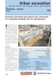
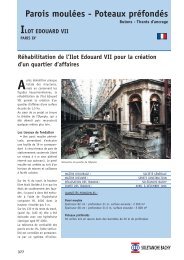
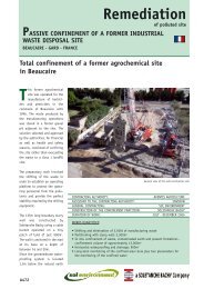
Overview of the terminal<br />
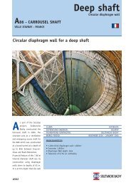
The reservoir is a <strong>shaft</strong> with an<br />
internal diameter of 90.50m<br />
and a storage capacity of<br />
140,000m 3 . The other three<br />
A507
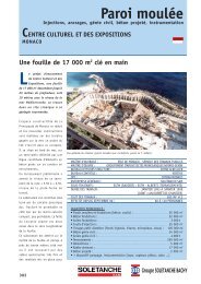
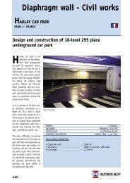
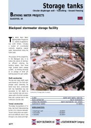
Construction of the diaphragm wall<br />
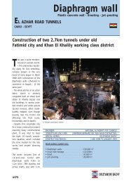
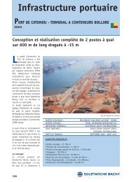
Earthmoving<br />
reservoirs were constructed by<br />
Solétanche <strong>Bachy</strong> in 1982 using a<br />
1,5m thick diaphragm wall and a<br />
800mm thick inner wall. Advances in<br />
design methodology made possible a<br />
lighter structural solution for this<br />
new reservoir : it uses a 1.20m thick<br />
diaphragm wall down to a depth of<br />
39.50m, with an excavated depth of<br />
25m (in part of 28m) .<br />
As the project is located on a gas<br />
storage site, particular attention was<br />
paid to safety and procedures were<br />
tightened as a consequence.<br />
There were further challenging<br />
requirements: a minimum concrete<br />
strength of 40MPa was needed to<br />
meet the calculated stress levels in<br />
the arch form wall. This, in turn was<br />
dependent on a 0.5% verticality<br />
tolerance and perfect wall continuity<br />
between panels. These requirements<br />
gave rise to a need for increased<br />
quality control to monitor the works<br />
on a continuous and daily basis.<br />
The walls were constructed using a<br />
KS3/2 steerable hydraulic grab and a<br />
mechanical grab, both equipped with<br />
vertical alignment recording systems.<br />
The circular diaphragm wall construction<br />
comprised 43 panels measuring<br />
6.68m in length and 39.5m in depth<br />
(the wall’s developed length along the<br />
circular wall axis = 287m). The excavation<br />
of the diaphragm walls passed<br />
through fill, clayey sand and compact<br />
sand with a 3m minimum embedment<br />
into clay.<br />
CWS joints (stop end with waterstop)<br />
were used for the connection between<br />
panels. Vertical alignment, including<br />
any twisting, was very closely monitored<br />
in order to ensure good circular<br />
wall continuity.<br />
Once the diaphragm wall had been<br />
completed, the construction of the<br />
concrete capping beam was commenced,<br />
followed by bulk excavation inside<br />
the wall.<br />
Nine inclinometer tubes and 24 strain<br />
gauges were integrated into the wall<br />
for the purpose of monitoring its<br />
behaviour during the bulk excavation<br />
inside the <strong>shaft</strong> and during construction<br />
of the LNG tank.<br />
Overview of the terminal<br />
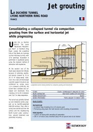
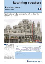
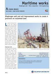
3D study of movement as the diaphragm wall buckles<br />
A507