
Create successful ePaper yourself
Turn your PDF publications into a flip-book with our unique Google optimized e-Paper software.
WBG-2,-3 & -5<br />
6. MOUNTING AND DISMOUNTING<br />
Always fit the supplied pins and retaining clips and check whether<br />
they are locked securely!<br />
The standard version is based on a three-point linkage: Category II three-point linkage. ( = lift pins ∅<br />
28 mm, top link pin ∅ 25 mm and retaining clips ∅ 11 mm and ∅8 mm).<br />
This machine can also be fitted with a Category III three-point linkage (= lift pins ∅ 36,5 mm, top link<br />
pin ∅ 31,5 mm and retaining clips ∅ 11 mm).<br />
Do not use pins with a smaller diameter!<br />
Make sure that the three point linkage has enough stabilisation to the side! The machine should not<br />
be able to move more than 5 cm sideways.<br />
During mounting, dismounting and transport of the machine, the power lift of the tractor must be in<br />
position control, and must be protected against accidental lowering!<br />
6.1 Mounting<br />
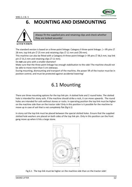
There are three mounting options for the top link pin. A slotted hole and 2 round holes. The slotted<br />
hole is intended for stony soils. If the machine should strike a rock, it can move upwards. The round<br />
holes are intended for soils without stones or rocks. In operating position the top link must be higher<br />
on the machine side than on the tractor side! Only in this position is it possible for the machine to<br />
move up in case of soil that is not completely flat (fig 6.1)<br />
In stony soil the top link must be placed between the special slotted holes. Ensure that the supplied<br />
slotted hole washers are placed on both sides of the top link pin. Only in this position can the front<br />
gang move up when it hits a large stone.<br />
Fig 6.1 The top link must be higher on the machine side than on the tractor side!<br />
SWARD LIFTER<br />
12