
Create successful ePaper yourself
Turn your PDF publications into a flip-book with our unique Google optimized e-Paper software.
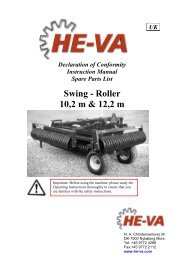
OPERATION MANUAL & SAFETY INSTRUCTIONS<br />
SWARD LIFTER<br />
WBG-2, WBG-3 & WBG-5<br />
OPICO LIMITED<br />
Cherry Holt Road<br />
Bourne<br />
Lincolnshire PE10 9LA<br />
Telephone: 01778 421111<br />
Fax: 01778 425080<br />
Email: ask@opico.co.uk<br />
Website: www.opico.co.uk<br />
Version: 12 04 Sward Lifter PV<br />
Version: 10 07 WBG3-5 PV
WBG-2,-3 & -5<br />
INDEX<br />
GLOSSARY ........................................................................................................................ 3<br />
INTRODUCTION ................................................................................................................ 4<br />
1. PURPOSE OF THE SWARD LIFTER ............................................................................... 5<br />
2. LIABILITY AND WARRANTY ........................................................................................ 5<br />
3. DANGER AND SAFETY DECALS.................................................................................... 5<br />
4. THE LOCATION OF THE DECALS .................................................................................. 7<br />
5. SAFETY INSTRUCTIONS .............................................................................................. 9<br />
5.1 GENERAL ........................................................................................................................... 9<br />
5.2 ROAD TRANSPORT AND USE ................................................................................................... 9<br />
5.3 MOUNTING AND DISMOUNTING ........................................................................................... 10<br />
5.4 MAINTENANCE .................................................................................................................. 10<br />
5.5 TYRES .............................................................................................................................. 11<br />
6. MOUNTING AND DISMOUNTING ............................................................................. 12<br />
6.1 MOUNTING ...................................................................................................................... 12<br />
6.2 DISMOUNTING AND STORING ............................................................................................... 13<br />
7. ADJUSTING SWARD LIFTER. ..................................................................................... 14<br />
7.1 ADJUSTING THE WORKING DEPTH .......................................................................................... 14<br />
8. INSTRUCTIONS FOR USE .......................................................................................... 14<br />
9. MAINTENANCE ........................................................................................................ 15<br />
9.1 GENERAL ......................................................................................................................... 15<br />
9.2 LUBRICATION .................................................................................................................... 16<br />
10. TECHNICAL SPECIFICATIONS .................................................................................... 17<br />
11. ORDERING PARTS .................................................................................................... 18<br />
12. EC CERTIFICATE OF CONFORMITY ............................................................................ 19<br />
APPENDIX I: PARTS LIST ................................................................................................ 20<br />
I.1 TINES AND SHARES: ........................................................................................................... 20<br />
I.2 DISC GRASSLAND SWARD LIFTER: .......................................................................................... 21<br />
I.3 SPINDELBRACKET ............................................................................................................... 22<br />
I.3 PRISMA ROLLER GRASSLAND SWARD LIFTER ............................................................................. 23<br />
I.4 GENERAL-PURPOSE ............................................................................................................ 24<br />
I.5 IDENTIFICATION PLATE, PATENT PLATE AND SAFETY DECALS ......................................................... 25<br />
SWARD LIFTER 2
WBG-2,-3 & -5<br />
GLOSSARY<br />
If you come across this symbol and heading, there is a direct<br />
hazard to life and health of man and animal!<br />
This heading refers to possible risks of damage to machine(s),<br />
crops, buildings, etc. But also to possible financial and/or legal<br />
problems (warranty, liability, and the like)!<br />
NOTE<br />
This indicates a tip to make work easier, better and safer.<br />
All figures, dimensions and weights are free of engagement.<br />
References to direction in the text, such as "left", "right", "front" and "rear", are always meant to be<br />
seen from the forward travel direction of the tractor.<br />
The same applies to the directions clockwise and counter clockwise.<br />
SWARD LIFTER<br />
3
WBG-2,-3 & -5<br />
INTRODUCTION<br />
Dear user,<br />
This is the operation manual for the WGB-2, WGB-3 and WBG-5 Sward Lifter Grassland Subsoiler.<br />
Read the operation manual carefully before starting to work with<br />
the machine and observe all instructions!<br />
Pass on all safety instructions to other (fellow) users!<br />
In order to use the Sward Lifter as safely as possible, you should be well aware of all<br />
recommendations and instructions in this manual. Damage and accidents caused by non-observance<br />
of these recommendations and instructions are your responsibility.<br />
Please ensure that this operation manual is kept in a safe place for future reference.<br />
If you have any more questions after reading this manual, please contact your dealer.<br />
EVERS AGRO B.V.<br />
Almelo, 16 April 2012<br />
SWARD LIFTER<br />
4
WBG-2,-3 & -5<br />
1. PURPOSE OF THE SWARD LIFTER<br />
Field of application<br />
The Sward Lifter is solely for use in regular arable farming. The Sward Lifter is designed to break up<br />
pans and surface compaction while lifting and opening up the subsoil for improved aeration and<br />
drainage.<br />
Important features of the grassland subsoiler are:<br />
<br />
the spring loaded cutting discs that cut through the <strong>sward</strong> to prevent soil bursting on<br />
to the surface.<br />
Shear-bolt protected leg that breaks back to prevent damage.<br />
Spring-loaded press rollers that close the slots and level the surface.<br />
Any deviating use is considered not matching the intended<br />
purpose. The user bears the risk of any damage and/or accidents.<br />
The above does not apply if in advance written approval has been<br />
obtained from the manufacturer!<br />
2. LIABILITY AND WARRANTY<br />
Anyone operating the machine, or carrying out adjustments or maintenance should read this manual<br />
carefully and observe the instructions to prevent danger.<br />
That also means:<br />
1. That work may only be carried out within the functional limits (e.g. max. speed), as laid down<br />
in the instructions for operation, maintenance and repair.<br />
2. That locally applying regulations for accident prevention, safety, traffic and transport are to<br />
be observed.<br />
3. That exclusively original or equivalent parts and lubricants must be used and mounted<br />
according to the instructions. A part and/or lubricant is considered equivalent when it has<br />
been approved by the manufacturer or when it can be demonstrated that it has the<br />
properties required for the function(s) in question.<br />
4. That any changes / modifications on the machine that have not been approved in writing by<br />
the manufacturer, exclude all liability of the manufacturer for any damage.<br />
Non-observance observance of the above rules shall be considered negligence.<br />
It will rule out any liability of the manufacturer for all possible<br />
damage and/or consequences.<br />
The user is fully en solely responsible for any risk!<br />
SWARD LIFTER<br />
3. DANGER AND SAFETY DECALS<br />
5
WBG-2,-3 & -5<br />
Working safely also means that you take proper notice of the<br />
various decals on the machine. You must know what they warn<br />
you for!<br />
There are a number of safety decals on the machine. The ones used and there place on this machine<br />
are shown on the next page.<br />
They have the following meaning:<br />
Danger:<br />
Stop the engine and remove the key from the ignition when<br />
working on the machine!<br />
Attention:<br />
Carefully read the operating manual before taking the machine<br />
into operation!<br />
Danger:<br />
There is a risk of flying objects and / or clods!<br />
Keep clear!<br />
Danger:<br />
Keep away from the fold-down down parts when the locking pins with<br />
inserted retaining clip are not mounted!<br />
Keep clear!<br />
SWARD LIFTER<br />
6
WBG-2,-3 & -5<br />
Danger:<br />
There is a risk of parts folding down!<br />
Fix the locking pins with inserted retaining clip!<br />
Danger:<br />
Never stand between the tractor and the machine when the<br />
power lift is being operated!<br />
Danger:<br />
Risk of injection at a leaking hydraulic system!<br />
Liquid under pressure easily penetrates through skin and clothing<br />
this can cause heavy injuries!<br />
Danger:<br />
In operating position the top link must<br />
be higher on the machine side than on<br />
the tractor side!<br />
4. THE LOCATION OF THE DECALS<br />
SWARD LIFTER 7
WBG-2,-3 & -5<br />
Fig 4.1 The location of the decals.<br />
If decals are loose, have become illegible or are no longer on the<br />
machine, these must be replaced as well!<br />
SWARD LIFTER<br />
8
WBG-2,-3 & -5<br />
5. SAFETY INSTRUCTIONS<br />
Read and understand these instructions before working with the<br />
machine!<br />
If these safety instructions aren’t observed, all liability of the<br />
manufacturer for any damage is excluded!<br />
5.1 General<br />
• The machine must only be used, operated and maintained by people who are familiar with<br />
the machine and who are aware of the risks!<br />
• The operator should familiarise him-/herself with all controls and their functions before<br />
starting work. During work could be too late!<br />
• In addition to the specific instructions of this manual, you should also study the general<br />
regulations for safety and accidents prevention in your country!<br />
5.2 Road transport and use<br />
• Always observe the road traffic regulations when using public roads!<br />
• Check the safety of the machine and tractor before use as regards work and traffic!<br />
• Observe the maximum permissible axle load, total weight and transport dimensions!<br />
• Prior to road transport, check and mount transport accessories such as lighting, warning<br />
signs and any protective parts!<br />
• Put the machine in the position intended for road transport and lock it according to the<br />
instructions!<br />
• Always make sure that the machine has sufficient lateral stability in transport position!<br />
• In case of road transport with the machine in lifted position, the control lever of the power<br />
lift must be locked to prevent lowering!<br />
• Look around the machine and the tractor before driving off or starting to work. Make sure<br />
you have sufficient view. Look out for children!<br />
• It is strictly prohibited to be on the machine during work or transport!<br />
• The driver's seat must at all time be occupied during driving!<br />
• Handling, manoeuvrability and brake performance are influenced by mounted machines and<br />
front weights. Therefore, make sure you work with an adequate steering and breaking<br />
installation.<br />
• Always adapt the forward speed to the condition of the terrain!<br />
• When making turns, take into account the length/width (turning circle) and/or swinging out,<br />
due to the large mass of the machine!<br />
• Only work with machines with the protective provisions complete, intact and in the<br />
functional position!<br />
• There must be nobody within the operating and danger range (including turning and<br />
swinging circle) of the machine. At the rear of the machine clods or other objects may be<br />
flung away!<br />
• There must be nobody between the tractor and the machine, until the vehicle is prevented<br />
SWARD LIFTER 9
WBG-2,-3 & -5<br />
from moving by means of the parking brake and/or wheels chocks!<br />
• When leaving the tractor, put the machine on the ground, switch off the tractor engine and<br />
remove the ignition key!<br />
• The warning decals on the machine give important instructions for safe use; observing them<br />
is for your own safety!<br />
• The user must wear closely fitting clothes. Avoid loose clothing!<br />
• Always mount weights on the tractor according to the instructions on the fixation points<br />
intended for that purpose!<br />
5.3 Mounting and dismounting<br />
• Mount machines and accessories according to the instructions and mount the machine<br />
and/or parts/accessories only to the provisions intended for that purpose. Make sure they<br />
are locked effectively!<br />
• Special care must be taken when mounting or dismounting the machine on or off the tractor<br />
• When mounting or dismounting the machine on or off the three-point linkage, put the power<br />
lift control in a position in which inadvertently lifting or lowering is not possible!<br />
• For a three-point linkage the linkage category of the machine must always match that of the<br />
tractor!<br />
• The three-point linkage system constitutes a risk of accidents by getting caught and jackknifing.<br />
The same risk exists with the cylinders (if mounted) and the linkage arms and lifts<br />
rods!<br />
• The control for the three-point power lift outside the tractor cab must be operated without<br />
getting between the tractor and the machine!<br />
• The release ropes for quick coupler should hang freely and in the lowered position must not<br />
release the quick coupler by themselves!<br />
5.4 Maintenance<br />
• Repair, maintenance and cleaning activities, as well as repairing malfunctions, must only be<br />
carried out with the tractor engine switched off. Remove the ignition key!<br />
• When the machine is in the lifted position for repair, cleaning or maintenance, support legs<br />
must be used. Only work on a firm surface!<br />
• Regularly check to ensure all bolts and nuts are tight. Tighten if necessary!<br />
• Parts must at least satisfy the technical specifications prescribed by the manufacturer!<br />
• Always check whether replaced and/or dismounted parts are mounted correctly before using<br />
the machine again!<br />
• Ensure that any damage is repaired at once before using the machine again!<br />
• When conducting electrical welding operations on the tractor or on the mounted implement<br />
remove cable from the generator and the battery!<br />
• Before working on the electric gear disconnect battery cables!<br />
• When replacing cutting edges, always use the suitable tools and gloves!<br />
• Dispose of old oils and grease as prescribed by law.<br />
• After using the machine and/or cleaning, grease the rams of the cylinders to prevent<br />
corrosion.<br />
SWARD LIFTER 10
WBG-2,-3 & -5<br />
After using the machine and/or after cleaning the machine with<br />
water, grease the rams of the cylinders to prevent corrosion!<br />
5.5 Tyres<br />
• Fitting tyres requires knowledge and special tools!<br />
• When working on the tyres, make sure that the machine has been placed on the ground<br />
safely and that it is secured by chocks against unintentional rolling!<br />
• Repair work on tyres may only be conducted by trained staff and with suitable tools!<br />
• Check the tyres regularly and replace them in case of deterioration and damage. New tyres<br />
must satisfy the technical specifications prescribed by the manufacturer!<br />
• Check the pressure of the tyres regularly and adhere to the advised air pressure. (See table).<br />
• In case of doubt, contact your dealer or see a tyre tension table.<br />
Tyre<br />
Max.<br />
speed<br />
Min. pressure in<br />
Bar<br />
Best pressure in<br />
Bar<br />
Max. Pressure in<br />
Bar<br />
195 65/15 30 km/h<br />
2 2,5 3<br />
10.0/75 - 15,3<br />
14pr<br />
40km/h<br />
3.5 5.5 7<br />
SWARD LIFTER<br />
11
WBG-2,-3 & -5<br />
6. MOUNTING AND DISMOUNTING<br />
Always fit the supplied pins and retaining clips and check whether<br />
they are locked securely!<br />
The standard version is based on a three-point linkage: Category II three-point linkage. ( = lift pins ∅<br />
28 mm, top link pin ∅ 25 mm and retaining clips ∅ 11 mm and ∅8 mm).<br />
This machine can also be fitted with a Category III three-point linkage (= lift pins ∅ 36,5 mm, top link<br />
pin ∅ 31,5 mm and retaining clips ∅ 11 mm).<br />
Do not use pins with a smaller diameter!<br />
Make sure that the three point linkage has enough stabilisation to the side! The machine should not<br />
be able to move more than 5 cm sideways.<br />
During mounting, dismounting and transport of the machine, the power lift of the tractor must be in<br />
position control, and must be protected against accidental lowering!<br />
6.1 Mounting<br />
There are three mounting options for the top link pin. A slotted hole and 2 round holes. The slotted<br />
hole is intended for stony soils. If the machine should strike a rock, it can move upwards. The round<br />
holes are intended for soils without stones or rocks. In operating position the top link must be higher<br />
on the machine side than on the tractor side! Only in this position is it possible for the machine to<br />
move up in case of soil that is not completely flat (fig 6.1)<br />
In stony soil the top link must be placed between the special slotted holes. Ensure that the supplied<br />
slotted hole washers are placed on both sides of the top link pin. Only in this position can the front<br />
gang move up when it hits a large stone.<br />
Fig 6.1 The top link must be higher on the machine side than on the tractor side!<br />
SWARD LIFTER<br />
12
WBG-2,-3 & -5<br />
When setting the working depth, the top link pin must be at the back of the slotted hole.<br />
• When the machine is in working position, the tractors power lift must be in floating position<br />
(see the manual of the tractor).<br />
• Adjust the check rods or chains of the tractor correctly to prevent lateral sway.<br />
6.2 Dismounting and storing<br />
• Make sure that the tractor hydraulic is set to position control.<br />
• It is important to thoroughly clean the machine with water.<br />
• The bearings and joints should also be greased as prescribed in chapter 9 Maintenance.<br />
• Dispose of old oils and grease as prescribed by law.<br />
• Let the machine rest on a flat soil.<br />
• Let the roll rest on the ground or on solid wooden blocks with enough stability.<br />
• A roll made of synthetic material must be supported on the metal parts by wooden blocks,<br />
the synthetic material should not touch the ground, else it will deform.<br />
• Make sure the machine has enough stability.<br />
• Dismount the machine from the tractor.<br />
• Grease the rams of the cylinders to prevent corrosion.<br />
SWARD LIFTER 13
WBG-2,-3 & -5<br />
7. ADJUSTING SWARD LIFTER.<br />
NOTE<br />
The mounting height depends on the tyre size of the tractor. It is<br />
recommended to have the lower links as level as possible, while the top link<br />
is mounted higher to the machine than to the tractor.<br />
7.1 Adjusting the working depth<br />
The working depth of the grassland Sward <strong>lifter</strong> with the prisma roller is controlled by the hydraulics<br />
of the tractor (please consult your tractor manual for this) and the adjustment of the prisma rollers<br />
at the rear side of the Sward <strong>lifter</strong>.<br />
Calibration of the prisma rollers is carried out by adjusting the springs at the rear of the machine.<br />
The tighter the spring is stretched, the shallower the machine will work. It is important that the<br />
springs are not too tightly stretched as this will lift the Sward Lifter out of the ground,<br />
To adjust the maximum depth, use the pin holes above the rollers. When adjusting the rollers, the<br />
depth of the cutting disc must be adjusted at the same time, +/- 5-8 cm into the ground and this is<br />
done by using the adjusting rings. This calibration is very important as the cutting discs prevent soil<br />
bursting on to the surface.<br />
While working the <strong>sward</strong> <strong>lifter</strong> without the depth-pins the maximum traction on the tractor wheels is<br />
achieved. With the depth-pins the maximum pressure on the prisma rollers is assured,<br />
Important:<br />
Make sure that the machine is completely horizontal, if this is not the case it can be adjusted with the<br />
top link.<br />
8. INSTRUCTIONS FOR USE<br />
• It is forbidden to make tight turns with the machine in working position.<br />
• It is not advisable to use the grassland Sward Lifter on ground where there is a lot of<br />
heavy stones (stones >15cm)<br />
• The machine can only work properly when travelling forward.<br />
• Set the rate of drop of the power lift in such a manner that when lowering into the soil or<br />
putting down, the machine does not bump on the ground, so as to prevent damage to tines<br />
and shares.<br />
• When lifting the machine out of the soil, this is best achieved whilst moving the tractor<br />
slightly backwards.<br />
SWARD LIFTER 14
WBG-2,-3 & -5<br />
9. MAINTENANCE<br />
See chapter 5 “SAFETY INSTRUCTIONS” sub 5.5 “Maintenance”<br />
When the machine is in lifted position for repair, cleaning and<br />
maintenance activities, support legs must be placed under the machine<br />
and it must rest on them.<br />
Switch off the engine and remove the ignition key!<br />
9.1 General<br />
• Regularly check whether all bolts and nuts are tight.<br />
• Also check the bearings of the roller regularly.<br />
• After maintenance always check that the bearings are remounted correctly.<br />
• Check the hydraulic hoses, pipes and all connections regularly and replace them if there is<br />
any deterioration or damage.<br />
• Clean the machine with water after every use.<br />
• When the machine has been in contact with manure, the bearings of the roller must be filled<br />
with grease, to counteract the aggressive influence of ammonia.<br />
• It is important to thoroughly clean the machine with water. It is recommended to grease the<br />
rams of the cylinders to prevent corrosion!<br />
After using the machine and/or after cleaning the machine with<br />
water, grease the rams of the cylinders to prevent corrosion!<br />
The disc blades are sharp. Avoid wrenches slipping when working<br />
near the disc blades. Avoid climbing on machine above the disc<br />
gangs where there is possibility of slipping or falling. Serious injury<br />
could occur!<br />
SWARD LIFTER<br />
15
WBG-2,-3 & -5<br />
9.2 Lubrication<br />
Grease nipples are installed in the following places.<br />
A) The bearings of the cutting discs.<br />
B) The bearings of the prisma rollers.<br />
Every 20 working hours<br />
The bearings must be topped up with grease every 20 working hours, after cleaning the grease<br />
nipples, with a properly working manual grease gun, until pressure is clearly felt. Usually two strokes<br />
of the gun will suffice. Directly after greasing, the disc must be turned at least one revolution. Never<br />
use a compressor gun. Too high pressure can damage the grease sealing ring, causing fine soil<br />
particles to enter the bearing housing. When the machine is not to be used for any length of time, it<br />
is recommended that coat of grease or oil is applied, particularly when the machine has been in<br />
contact with manure. Dispose of old oils and grease as prescribed by law.<br />
SWARD LIFTER 16
WBG-2,-3 & -5<br />
10. TECHNICAL SPECIFICATIONS<br />
Technical specifications grassland Sward <strong>lifter</strong>:<br />
Type WBG-2 WBG-3 WBG-5<br />
Tinetype MT MT MT<br />
Number of tines 2 3 5<br />
Tine spacing (cm) 180 75 OR 90 75<br />
Share width (cm) 6 6 6<br />
Tine position | | V W<br />
Working depth max. (cm) 50 50 50<br />
Working width (cm) 180 225 - 270 375<br />
Transport width (cm) 270 270 270<br />
Tractor power (minimum HP) 70 90 130<br />
Tractor power (minimum kW) 52 66 95<br />
Linkage category II II II<br />
Gewicht (kg) 530 790 1215<br />
The noise level of the grassland Sward <strong>lifter</strong> does not exceed 70dB(A) during work.<br />
SWARD LIFTER 17
WBG-2,-3 & -5<br />
11. ORDERING PARTS<br />
Contact your local dealer to order spare parts.<br />
Please state the following data when ordering parts.<br />
1. Machine Type (MT) and the production identification number (PIN), this information can be<br />
found on the EC certificate of conformity.<br />
2. Name, article number and quantity of the article.<br />
If you are not sure of the correct part number of a part, you can take it to your local dealer or send in<br />
the original to prevent incorrect delivery.<br />
If decals are loose, have become illegible or are no longer on the<br />
machine, these must be replaced as well!<br />
SWARD LIFTER<br />
18
WBG-2,-3 & -5<br />
12. EC CERTIFICATE OF CONFORMITY<br />
EG-VERKLARING VAN OVEREENSTEMMING<br />
EC-DECLARATION OF CONFORMITY FOR MACHINERY<br />
EG-MASCHINENÜBEREINSTIMMUNGSERKLÄRUNG<br />
DÉCLARTION DE CONFORMITÉ “CE” POUR MACHINES<br />
Fabrikant/Manufacturer/Fabrikant/Fabricant:<br />
EVERS AGRO B.V.<br />
Adres/Address/Adresse/Adresse:<br />
Bedrijvenpark Twente 326<br />
7602 KL Almelo<br />
The Netherlands<br />
Verklaart hier mee dat/Herwith declares that/Erklärt hiermit das/Déclaré ci-après que<br />
Machine type/Machine type/Maschine Type/Type de machine:<br />
Ordernummer/Order number/Bestellnummer/Numèro de commande:<br />
Naam/Name/Name/Nom:<br />
Machine/Machine/Maschine/Machine:<br />
Product identificatie nummer/Product identification number/<br />
Produkt Indintifikation Nummer/ Numèro l’identification de produit:<br />
Gewicht/Weight/Gewicht/Masse:<br />
Paste sticker here<br />
<br />
<br />
<br />
<br />
Voldoet aan de bepalingen van de Machinerichtlijn (Richtlijn 2006/42/EG, zoals laatstelijk gewijzigd)<br />
en de nationale wetgeving ter uitvoering van deze richtlijn;<br />
Is in conformity with the provisions of the Machine Directive (Directive 2006/43/EC, as amended) and<br />
with national implementing legislation;<br />
Konform ist mit den einschlägigen Bestimmungen der EG-Maschinerichtlinie (EG-Richtlinie<br />
2006/42/EG), inclusive deren Änderunge, sowie mit dem entsprechenden Rechtserlaβ zur Umsetzung<br />
der Richtlinie in nationales Recht;<br />
Est conforme aux dispositions de la Directive “Machines” (Directive 2006/42/EC telle que dernièrement<br />
modifiée) et la législation nationale adoptée en application de ladite directive.<br />
Almelo, 16 April 2012<br />
G.J. Kamp,<br />
Director<br />
SWARD LIFTER<br />
19
WBG-2,-3 & -5<br />
APPENDIX I: PARTS LIST<br />
I.1 Tines and Shares:<br />
C<br />
D<br />
A<br />
B<br />
E<br />
F<br />
F<br />
G<br />
Pos. Part no. Description<br />
A 990313 Tine without wear knife and without point<br />
B 990387 Wear knife<br />
C 990190 Tension bush for tine (25,5 x 25 mm)<br />
C* 990191 Tension bush for machine (25,5 x 15 mm)<br />
D 990130 Pivoting bolt<br />
E* 990120 Shear bolt Quality 10.9<br />
F 990266 Chisel point 6 cm wide<br />
G 990267 Chisel point 20 cm wide (winged)<br />
H 101206 Bolt for mounting chisel point M12X60 8.8<br />
SWARD LIFTER 20
WBG-2,-3 & -5<br />
I.2 Disc grassland Sward <strong>lifter</strong>:<br />
12<br />
11<br />
13<br />
14<br />
15<br />
Pos. Part no. Description<br />
1 102012 Bolt M20x120 Qual. 8.8<br />
2 990488 Bolt M20x130 Qual. 8.8 threadlength 22 mm<br />
3 992241 Turning handle spindle adjuster<br />
4 100020 Nut M20 Qual. 8<br />
5 992243 Spindel inner tube Sward <strong>lifter</strong><br />
6 992244 Spindle outer tube Sward <strong>lifter</strong><br />
7 992242 Ring + depth marker spindle adjuster Sward <strong>lifter</strong><br />
8 992229 Locking pin for Spindle adjuster<br />
9 992236 Fork Spindle adjuster Sward <strong>lifter</strong> lower part<br />
10 100120 Self-locking locking nut M20 Qual. 8<br />
11 992202 Adjusting spindle Disc leg (Incl. disc 12 and hub 15)<br />
12 990082 Disc Ø 35 cm<br />
13 993041 Spring L=234 mm (WBG)<br />
13* 903055 Spring L=200<br />
Spring L=200 mm (WBGH centre disc only)<br />
14 992217 Eye bolt<br />
15 990093 Hub<br />
16 100802 Bolt for mounting disc to the hub<br />
17 990485 Bolt for mounting hub to the spindle<br />
18 992972 Bushes for hub bolt 990485<br />
SWARD LIFTER<br />
21
WBG-2,-3 & -5<br />
I.3 Spindelbracket<br />
8 + 9<br />
10<br />
6<br />
7<br />
11<br />
8 + 9<br />
1 + 2<br />
8<br />
3 + 4<br />
12<br />
Pos. Part no. Description<br />
1 992237 Bracket spindle mounting WBG (left / right)<br />
2 992238 Bracket spindle mounting WBGH (left / right)<br />
3 992239 Bracket spindle mounting WBG (center)<br />
4 992240 Bracket spindle mounting WBGH (center)<br />
5 992973 Bush Ø 40x20 L=16,5<br />
6 191611 Eye bolt M16x110<br />
7 191613 Eye bolt M16x130<br />
8 100216 Ring M16<br />
9 100116 Self-locking nut M16<br />
10 101616 Bolt M16 X 160 8.8<br />
11 101620 Bolt M16 X 200 8.8<br />
12 990488 Bolt voor mounting spindle M20x130 8.8<br />
13 100120 Self-locking nut M20 for 990488<br />
SWARD LIFTER 22
WBG-2,-3 & -5<br />
I.3 Prisma roller grassland Sward <strong>lifter</strong><br />
J<br />
K<br />
Pos. Part no. Description<br />
A G 75420 Prisma ring (Casted steel)<br />
B G 75421 Prisma ring short (Casted steel)<br />
C 990200 Bearing SBF 207, shaft Ø35 mm<br />
D G 71195 Clips on shaft<br />
E G 70180 Distance washer synthetic (16 mm)<br />
F G 13550 Spacer metal<br />
G G 90501 Square shaft 45<br />
H+I G 10707 Scraper<br />
H G 10701 Scraper tine<br />
I G 10706 Scraper clip<br />
J 992206 Depth control pin ∅ 20mm<br />
K 993041 Spring roller<br />
SWARD LIFTER 23
WBG-2,-3 & -5<br />
I.4 General-purpose<br />
D<br />
Pos. Part no. Description<br />
A 992213 Top link pin Ø25 mm<br />
A* 992207 Top link pin Cat 3<br />
B 992204 Lower hitch pin Ø28 mm, Cat. 2<br />
B* 992208 Lower hitch pin Cat 3<br />
C 992206 Depth control pin ∅ 20mm<br />
D 990220 Support leg WBG<br />
D* 990208 Support leg WBGH<br />
SWARD LIFTER 24
WBG-2,-3 & -5<br />
I.5 Identification plate, patent plate and<br />
safety decals<br />
A<br />
B<br />
C D E F G I<br />
H<br />
Pos. Part no. Description<br />
A 992061 Indentification plate<br />
B 992062 Patent plate, Evers disc harrow Vario-Disc<br />
C 992054 Safety decal “Read operation and safety instructions<br />
D 992055 Safety decal “Do not stay between tractor and machine”<br />
E 992056 Safety decal “Keep clear”<br />
F 992057 Safety decal “Keep away from folding parts”<br />
G 992058 Safety decal “Fix locking pins with inserted retaining clip”<br />
H 992066 Attention decal “Correct mounting toplink between tractor and machine”<br />
I 992063 Safety decal “Watch out for hydraulic leakings”<br />
SWARD LIFTER 25