Hitchhiker's Guide to the Dilution Refrigerator - Harvard University ...
Hitchhiker's Guide to the Dilution Refrigerator - Harvard University ...
Hitchhiker's Guide to the Dilution Refrigerator - Harvard University ...
Create successful ePaper yourself
Turn your PDF publications into a flip-book with our unique Google optimized e-Paper software.
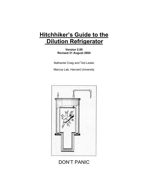
Hitchhiker’s <strong>Guide</strong> <strong>to</strong> <strong>the</strong><br />
<strong>Dilution</strong> Refrigera<strong>to</strong>r<br />
Version 2.00<br />
Revised 21 August 2004<br />
Nathaniel Craig and Ted Lester<br />
Marcus Lab, <strong>Harvard</strong> <strong>University</strong><br />
DON’T PANIC
Hitchhiker’s <strong>Guide</strong> <strong>to</strong> <strong>the</strong> <strong>Dilution</strong> Refrigera<strong>to</strong>r<br />
Nathaniel Craig and Ted Lester, revised 21 August 2004<br />
INTRODUCTION<br />
DON'T PANIC. A dilution refrigera<strong>to</strong>r, at first blush, appears <strong>to</strong> be a horribly, intricately, awfully<br />
twisted labyrinth of tubes and valves and KF flanges designed with <strong>the</strong> sole purpose of hastening<br />
a physics student's descent in<strong>to</strong> madness. This is, <strong>to</strong> a large extent, quite true. None<strong>the</strong>less,<br />
much of <strong>the</strong> mystery of dil fridge operation may be dispelled by a bit of hands-on experience and<br />
a few helpful pointers. No compilation of notes can supplant <strong>the</strong> wisdom of physical experience,<br />
but hopefully it can help <strong>to</strong> alleviate <strong>the</strong> fear and loathing that often accompany a first encounter<br />
with a dilution refrigera<strong>to</strong>r. This guide has been created in <strong>the</strong> hopes of providing a composite<br />
resource useful <strong>to</strong> familiarize a first-time user and remind an experienced hand. It is based upon<br />
a variety of sources, from <strong>the</strong> Oxford manual <strong>to</strong> past written notes <strong>to</strong> <strong>the</strong> ever-changing<br />
knowledge of various group members. We hope that it will remain a fluid document, updated and<br />
revised <strong>to</strong> suit <strong>the</strong> perpetual changes and developments that emerge in <strong>the</strong> lifetime of a<br />
refrigera<strong>to</strong>r. Many of <strong>the</strong>se notes are designed <strong>to</strong> be as generic as possible, but where relevant<br />
have been specialized for <strong>the</strong> Kelvinox 100 system known as <strong>the</strong> "Old Stanford Fridge". All<br />
Marcus lab dilution refrigera<strong>to</strong>rs follow very similar instructions, but a few steps are optimized for<br />
<strong>the</strong> particularities of <strong>the</strong> Stanford fridge, and various resistance, pressure, and time values vary<br />
from fridge <strong>to</strong> fridge. Much of this information is contained in (confusing and obscure) detail in <strong>the</strong><br />
Oxford fridge manual; departures from <strong>the</strong> standard procedure are usually noted when present.<br />
HISTORY AND PRINCIPLE OF OPERATION<br />
The first commercial 3He/4He dilution refrigera<strong>to</strong>r was produced by Oxford in 1967, 16 years after<br />
Loudon first proposed <strong>the</strong> principle of operation. Oxford has held a monopoly ever since, and has<br />
developed correspondingly horrendous cus<strong>to</strong>mer service. Its fridges are sound and reliable,<br />
although its service is certainly not. Such is <strong>the</strong> extent of <strong>the</strong> relevant his<strong>to</strong>ry.<br />
When a mixture of <strong>the</strong> two stable iso<strong>to</strong>pes of helium is cooled below a critical temperature, it<br />
separates in<strong>to</strong> two phases. The lighter "concentrated phase" is rich in 3He, and <strong>the</strong> heavier<br />
"dilute phase" is rich in 4He (confusing, no?). The concentration of 3He in each phase is<br />
temperature-dependent. Since <strong>the</strong> enthalpy of <strong>the</strong> 3He in <strong>the</strong> two phases is different, <strong>the</strong><br />
"evaporation" of 3He from <strong>the</strong> concentrated phase in<strong>to</strong> <strong>the</strong> dilute phase may provide highly<br />
effective cooling. In a gross simplification, <strong>the</strong> concentrated phase of <strong>the</strong> mixture is pretty much<br />
liquid 3He, and <strong>the</strong> dilute phase is effectively 3He gas. The 4He composing <strong>the</strong> bulk of <strong>the</strong> dilute<br />
phase is inert and noninteracting, and may be neglected. The evaporation of 3He from <strong>the</strong> "liquid"<br />
phase <strong>to</strong> <strong>the</strong> "gas" phase cools <strong>the</strong> sample. This process works even at <strong>the</strong> lowest temperatures<br />
because <strong>the</strong> equilibrium concentration of 3He in <strong>the</strong> dilute phase is finite even at zero<br />
temperature.<br />
When <strong>the</strong> refrigera<strong>to</strong>r begins operation, <strong>the</strong> 1K pot is used <strong>to</strong> condense <strong>the</strong> 3He/4He<br />
mixture in <strong>the</strong> dilution unit. It does not cool <strong>the</strong> mixture sufficiently <strong>to</strong> form <strong>the</strong> phase boundary,<br />
but simply <strong>to</strong> bring it <strong>to</strong> 1.2K. Phase separation may be attained only once <strong>the</strong> temperature falls<br />
below <strong>the</strong> tri-critical point at 0.86K. This cooling is provided by <strong>the</strong> still; incoming 3He is cooled by<br />
<strong>the</strong> still before it enters <strong>the</strong> heat exchangers and mixing chamber. Gradually, <strong>the</strong> rest of <strong>the</strong><br />
dilution unit cools <strong>to</strong> <strong>the</strong> point where phase separation occurs.<br />
It is important that <strong>the</strong> 3He concentration and volume of <strong>the</strong> mixture are chosen correctly,<br />
so that <strong>the</strong> phase boundary occurs inside <strong>the</strong> mixing chamber and <strong>the</strong> liquid surface lies in <strong>the</strong><br />
still. If this is not done, <strong>the</strong> fridge will not cool <strong>to</strong> base temperature. Thus it is CRITICAL <strong>to</strong><br />
preserve <strong>the</strong> balance of <strong>the</strong> mixture.<br />
During continuous operation, <strong>the</strong> 3He must be extracted from <strong>the</strong> dilute phase (<strong>to</strong> prevent<br />
saturation) and resupplied <strong>to</strong> <strong>the</strong> concentrated phase. The 3He is pumped away from <strong>the</strong> liquid<br />
surface in <strong>the</strong> still, where at ~0.6K 3He evaporates preferentially (1000 times faster than 4He).<br />
3He leaving <strong>the</strong> mixing chamber is used <strong>to</strong> cool <strong>the</strong> returning flow of concentrated 3He in a series<br />
of heat exchangers. A room temperature vacuum pumping system is used <strong>to</strong> remove 3He from<br />
<strong>the</strong> still and compress it before passing it through impurity-removing filters and cold traps (one at<br />
2
77K, <strong>the</strong> o<strong>the</strong>r at 4.2K) and returning it <strong>to</strong> <strong>the</strong> cryostat. The inflowing mixture is pre-cooled by <strong>the</strong><br />
main helium bath and condensed on <strong>the</strong> 1K pot. A flow impedance (in <strong>the</strong> form of a capillary tube)<br />
is used <strong>to</strong> maintain a sufficiently high pressure in <strong>the</strong> 1K pot region for <strong>the</strong> gas <strong>to</strong> condense.<br />
The experimental apparatus is mounted in <strong>the</strong> mixing chamber <strong>to</strong> ensure adequate <strong>the</strong>rmal<br />
contact.<br />
The dilution refrigera<strong>to</strong>r has been designed with a two-part external gas handling system.<br />
One part (<strong>the</strong> circulation system) is dedicated <strong>to</strong> <strong>the</strong> circulation and handling of <strong>the</strong> mixture, and<br />
<strong>the</strong> o<strong>the</strong>r (<strong>the</strong> auxiliary system) <strong>to</strong> auxiliary pumping operations. Both systems are connected <strong>to</strong><br />
<strong>the</strong>ir relevant components on <strong>the</strong> cryostat and fridge insert by flexible pumping lines.<br />
CIRCULATION SYSTEM (Fig. 10)<br />
The 3He is circulated by a mist-filtered sealed rotary pump. A digital Thermovac gauge is fitted <strong>to</strong><br />
measure <strong>the</strong> still pumping line pressure (P1); pump outlet pressure is measured by an analog<br />
gauge (G2). The 3He is fur<strong>the</strong>r purified by passage through an LN2 cold trap before flowing back<br />
in<strong>to</strong> <strong>the</strong> condenser line of <strong>the</strong> insert. A second analog gauge (G1) indicates <strong>the</strong> pressure in <strong>the</strong><br />
condenser line (when valve 1 is open) and <strong>the</strong> pressure drop across <strong>the</strong> cold trap. When <strong>the</strong><br />
system is not in use, <strong>the</strong> mixture is s<strong>to</strong>red in an external dump vessel. Access <strong>to</strong> <strong>the</strong> dump is<br />
primarily obtained through valve 9 and <strong>the</strong> two valves on <strong>the</strong> dump itself.<br />
AUXILIARY SYSTEM (Fig. 11)<br />
A small, open rotary pump drives <strong>the</strong> auxiliary gas handling system. This pump vents <strong>to</strong> air, and<br />
so should NEVER be opened <strong>to</strong> areas containing mixture. Ra<strong>the</strong>r, it is used primarily <strong>to</strong> pump <strong>the</strong><br />
1K pot (pulling 4He gas from <strong>the</strong> main bath) and clean cold traps at room temperature. The<br />
auxiliary system is connected <strong>to</strong> <strong>the</strong> circulation system through Vent 2 and Vent 1 on <strong>the</strong> back of<br />
<strong>the</strong> gas handling cabinet.<br />
3
COOLING DOWN<br />
UNBUTTONING THE DILUTION UNIT<br />
1) Allow inert gas (He or N2; preferably not air) in<strong>to</strong> <strong>the</strong> IVC can via <strong>the</strong> IVC valve.<br />
2) Break <strong>the</strong> old indium seal by unscrewing <strong>the</strong> IVC bolts and placing bolts in <strong>the</strong> two dummy<br />
holes along <strong>the</strong> IVC can <strong>to</strong>p perimeter. Slowly screw each, in turn, until <strong>the</strong> indium seal breaks<br />
and <strong>the</strong> IVC can may be removed.<br />
3) Strip off <strong>the</strong> old indium seal and recycle <strong>the</strong> indium.<br />
4) Blow away remaining pieces of indium with an air gun.<br />
5) Gently scotch brite <strong>the</strong> two surfaces forming <strong>the</strong> indium seal.<br />
6) Swab off remaining spots of indium or debris with a Q-tip and methanol. Take care <strong>to</strong> leave no<br />
cot<strong>to</strong>n fibers on <strong>the</strong> sealing surfaces.<br />
7) Remove <strong>the</strong> inner radiation seal and unscrew <strong>the</strong> socket cover; gently remove <strong>the</strong> old sample.<br />
BUTTONING UP THE DILUTION UNIT<br />
1) Test connections from sample <strong>to</strong> <strong>the</strong> BNC box; resistances can be checked against those<br />
listed in <strong>the</strong> fridge book. Be certain <strong>to</strong> check resistance <strong>to</strong> ground.<br />
2) Place chip carrier in socket. Check <strong>to</strong> ensure that <strong>the</strong> pins make good contact with <strong>the</strong> chip<br />
carrier.<br />
3) Screw on <strong>the</strong> socket cover. Screw on <strong>the</strong> inner radiation shield. These screws need only be<br />
finger tight.<br />
4) Remove <strong>the</strong> bot<strong>to</strong>m of <strong>the</strong> inner radiation shield (four screws) and check <strong>to</strong> make sure that<br />
<strong>the</strong>re are no <strong>to</strong>uches between <strong>the</strong> cold finger and <strong>the</strong> inner radiation shield. Replace <strong>the</strong> bot<strong>to</strong>m<br />
of <strong>the</strong> shield.<br />
5) Seal all openings in <strong>the</strong> inner radiation shield with copper tape. Make certain that <strong>the</strong>re are a<br />
few small holes in <strong>the</strong> tape <strong>to</strong> allow pumping.<br />
6) Form a new indium seal on <strong>the</strong> IVC can with lightly greased indium wire. Do not locate <strong>the</strong> joint<br />
in <strong>the</strong> indium near any of <strong>the</strong> IVC bolt apertures. slide <strong>the</strong> IVC can carefully on<strong>to</strong> <strong>the</strong> insert, <strong>the</strong>n<br />
begin tightening <strong>the</strong> IVC bolts. Proceed around in a circle, tightening every fourth bolt in small,<br />
equal increments (i.e., gently tighten <strong>the</strong> first bolt, skip <strong>the</strong> second and third, gently tighten <strong>the</strong><br />
fourth bolt, skip <strong>the</strong> fifth and sixth, etc.). In this way, you will tighten evenly around <strong>the</strong> circle.<br />
Tighten until sealed. Wait 30 minutes and attempt <strong>to</strong> tighten fur<strong>the</strong>r.<br />
7) Tie <strong>the</strong> pot intake line tightly <strong>to</strong> <strong>the</strong> IVC can with several loops of floss.<br />
8) Pump on <strong>the</strong> IVC using <strong>the</strong> leak detec<strong>to</strong>r for several hours or overnight. Check for leaks<br />
around <strong>the</strong> indium seal and <strong>the</strong> IVC valve.<br />
9) If <strong>the</strong> dilution unit has been warm or running for a long time, you can pump on <strong>the</strong> condenser<br />
line and still line by teeing a turbo <strong>to</strong> both <strong>the</strong> condenser line valve and <strong>the</strong> pumping line valve.<br />
Pump as with <strong>the</strong> IVC.<br />
INSERTING THE DILUTION UNIT INTO THE MAIN BATH DEWAR<br />
1) Magnet temperature at room temperature is ~173 ohms, measured with a Fluke and <strong>the</strong><br />
magnet temperature leads.<br />
2) Start with all valves on <strong>the</strong> gas handling cabinet and on <strong>the</strong> dilution unit closed.<br />
3) Lower <strong>the</strong> dilution unit in<strong>to</strong> <strong>the</strong> fridge dewar.<br />
4) Attach <strong>the</strong> IVC line, pot line, pumping line, and condenser line <strong>to</strong> <strong>the</strong> dilution unit, blowing<br />
some He gas through <strong>the</strong> lines first if desired. The <strong>to</strong>pology of <strong>the</strong> lines should allow enough<br />
freedom <strong>to</strong> later insert <strong>the</strong> LHe cold trap.<br />
5) Hook up <strong>the</strong> electrics and <strong>the</strong> RuO2 cable. Check <strong>the</strong> room temperature resistance bridge<br />
readings.<br />
6) Open 4a <strong>to</strong> pump out <strong>the</strong> pot line <strong>to</strong> 10-2 mbar. Open pot line valve <strong>to</strong> pump out <strong>the</strong> pot <strong>to</strong> 10-1<br />
mbar. Close <strong>the</strong> pot line valve and 4a.<br />
7) Blow He gas through <strong>the</strong> pot and pot line via a valved tee attached <strong>to</strong> <strong>the</strong> pot line just outside<br />
<strong>the</strong> pot valve. Open <strong>the</strong> pot valve and needle valve <strong>to</strong> flow He at 5-10psi throughout <strong>the</strong> entire<br />
process until 4K is attained.<br />
8) Connect positive bias if desired.<br />
[Variation on insertion for LN2 pre-cooling or cryostat pre-cooling: Begin blowing He gas<br />
4
through <strong>the</strong> pot system via valved tee while insert is suspended above <strong>the</strong> cryostat. Once <strong>the</strong><br />
insert is in <strong>the</strong> cryostat, close <strong>the</strong> needle valve, pot valve, and <strong>the</strong> tee valve. Attach <strong>the</strong> pot line <strong>to</strong><br />
<strong>the</strong> tee and evacuate <strong>the</strong> line via 4a. Close 4a, reopen <strong>the</strong> tee valve, wait until <strong>the</strong> pot line has<br />
filled with He gas, <strong>the</strong>n open <strong>the</strong> pot valve and needle valve <strong>to</strong> continue flowing He gas through<br />
<strong>the</strong> intake line.]<br />
ADMITTING EXCHANGE GAS INTO THE IVC<br />
1) A small amount of exchange gas (in this case, 4He) is necessary <strong>to</strong> establish <strong>the</strong>rmal contact<br />
between <strong>the</strong> dilution unit and <strong>the</strong> main bath in order <strong>to</strong> cool <strong>to</strong> 4K. You do NOT want ANY air <strong>to</strong><br />
enter <strong>the</strong> IVC along with <strong>the</strong> exchange gas, as water vapor and N2 in <strong>the</strong> air will freeze out during<br />
cooling and pose an unacceptable heat burden. Connect a turbo pump and a valved tee <strong>to</strong> <strong>the</strong><br />
IVC inlet valve. Evacuate <strong>the</strong> line <strong>to</strong> <strong>the</strong> IVC using <strong>the</strong> turbo for ~15 minutes.<br />
2) Attach He gas tube <strong>to</strong> valved tee in <strong>the</strong> line. Close off <strong>the</strong> turbo. Pinch off ~1m of gas tube,<br />
<strong>the</strong>n open <strong>the</strong> valve <strong>to</strong> allow <strong>the</strong> ~1m of gas in<strong>to</strong> <strong>the</strong> line. Close <strong>the</strong> valve.<br />
3) Rough out <strong>the</strong> lines in order <strong>to</strong> clear <strong>the</strong> just-introduced He. Repeat once or twice more <strong>to</strong> fully<br />
flush and pump <strong>the</strong> lines.<br />
4) Rough and turbo <strong>the</strong> line one final time for several minutes. Close off <strong>the</strong> pump. Pinch off one<br />
foot of gas tube, <strong>the</strong>n open <strong>the</strong> valve <strong>to</strong> allow <strong>the</strong> foot of gas in<strong>to</strong> <strong>the</strong> line. Open <strong>the</strong> IVC valve<br />
fully. Close <strong>the</strong> IVC valve. A fraction of this foot of gas will have entered <strong>the</strong> IVC can; this is your<br />
exchange gas. Disconnect <strong>the</strong> turbo from <strong>the</strong> IVC valve.<br />
TRANSFERRING LN2 TO THE FRIDGE DEWAR<br />
1) Insert LN2 transfer stick in<strong>to</strong> <strong>the</strong> transfer hole on <strong>the</strong> fridge dewar. The transfer stick should<br />
screw in entirely at <strong>the</strong> bot<strong>to</strong>m so that <strong>the</strong> bolt is ~2 inches above <strong>the</strong> <strong>to</strong>p of <strong>the</strong> transfer hole. Tug<br />
on <strong>the</strong> stick <strong>to</strong> ensure a tight seal.<br />
2) Connect <strong>the</strong> rubber tube from <strong>the</strong> liquid valve on <strong>the</strong> LN2 dewar <strong>to</strong> <strong>the</strong> transfer stick.<br />
3) Start <strong>the</strong> flow of LN2--slowly at first, <strong>the</strong>n open <strong>to</strong> full as <strong>the</strong> tube hardens.<br />
4) The main bath is full when <strong>the</strong> magnet temperature reaches and sustains ~200 ohms for 77K.<br />
This should take one <strong>to</strong> two hours.<br />
5) The dilution unit should cool within one hour of filling, as indicated by resistance bridge<br />
readings.<br />
6) Positive bias voltage reading should diminish sharply near 77K.<br />
7) Leave <strong>the</strong> transfer tube and stick connected in anticipation of...<br />
REMOVING LN2<br />
1) After <strong>the</strong> insert and main bath have cooled <strong>to</strong> 77K, <strong>the</strong> LN2 must be removed. Be prepared <strong>to</strong><br />
start LHe transfer soon after LN2 removal, as <strong>the</strong> dewar will warm quickly once empty.<br />
2) LN2 may be forced from <strong>the</strong> main bath and back in<strong>to</strong> <strong>the</strong> LN2 dewar by raising <strong>the</strong> pressure in<br />
<strong>the</strong> main bath and reducing <strong>the</strong> pressure in <strong>the</strong> LN2 dewar.<br />
3) Lower <strong>the</strong> pressure in <strong>the</strong> LN2 dewar by opening <strong>the</strong> vent valve on <strong>the</strong> LN2 dewar.<br />
4) Raise <strong>the</strong> pressure in <strong>the</strong> main bath by connecting an N2 gas line <strong>to</strong> <strong>the</strong> main vent of <strong>the</strong><br />
refrigera<strong>to</strong>r dewar (you can use He gas if N2 is unavailable, but N2 is preferable).<br />
5) Open <strong>the</strong> liquid valve on <strong>the</strong> LN2 dewar so that liquid may flow out of <strong>the</strong> main bath, through<br />
<strong>the</strong> transfer tube, and back in<strong>to</strong> <strong>the</strong> LN2 dewar.<br />
6) It will take ~1 hour <strong>to</strong> empty <strong>the</strong> main bath of LN2. When <strong>the</strong> bath is empty, condensed ice on<br />
<strong>the</strong> transfer tube will melt. When this occurs, close <strong>the</strong> vent and gas valves on <strong>the</strong> LN2 dewar and<br />
(carefully) remove <strong>the</strong> rubber transfer tube from <strong>the</strong> <strong>to</strong>p of <strong>the</strong> transfer stick (leave <strong>the</strong> stick in).<br />
Cold N2 gas should be flowing out of <strong>the</strong> <strong>to</strong>p of <strong>the</strong> transfer tube. Allow gas <strong>to</strong> continue flowing<br />
until <strong>the</strong> magnet resistance drops <strong>to</strong> ~198 ohms; in this way you may be certain that all LN2 has<br />
been evacuated from <strong>the</strong> dewar.<br />
7) Remove <strong>the</strong> LN2 transfer tube.<br />
5
LHe TRANSFER TO MAIN BATH (Not complete instructions; just a few reminders pertinent <strong>to</strong><br />
<strong>the</strong> initial transfer)<br />
1) Check that <strong>the</strong> outlet end of <strong>the</strong> LHe transfer tube has <strong>the</strong> correct nozzle. For <strong>the</strong> initial<br />
transfer, you should use a tip that opens straight down, as it is best <strong>to</strong> spray LHe <strong>to</strong> <strong>the</strong> bot<strong>to</strong>m of<br />
<strong>the</strong> empty main bath during <strong>the</strong> first transfer. For later transfers use <strong>the</strong> nozzle with side<br />
openings, since it's better <strong>to</strong> spray incoming LHe <strong>to</strong> <strong>the</strong> sides of <strong>the</strong> partially full bath <strong>to</strong> avoid<br />
excess splashing.<br />
2) Put <strong>the</strong> level meter sampling rate <strong>to</strong> high.<br />
3) Transfer philosophies vary, but during <strong>the</strong> initial transfer it is important <strong>to</strong> cool <strong>the</strong> insert as<br />
adiabatically as possible <strong>to</strong> avoid excess LHe blowoff. Use a very slow rate of flow; begin <strong>the</strong><br />
transfer without pressurizing <strong>the</strong> dewar, and allow dewar pressure <strong>to</strong> govern <strong>the</strong> transfer until <strong>the</strong><br />
dewars equilibrate. Then pressurize <strong>the</strong> LHe dewar at a VERY low pressure, ~1-2 psi. Cooling<br />
<strong>the</strong> magnet from 200 ohms (77K) <strong>to</strong> 300 ohms should take roughly one hour, but cooling <strong>the</strong><br />
remainder of <strong>the</strong> way <strong>to</strong> ~1084 ohms (4.2K) takes roughly fifteen minutes.<br />
4) Usually no more than 11 inches (~50L) of LHe are required <strong>to</strong> cool and fill <strong>the</strong> fridge dewar<br />
from 77K.<br />
5) Once <strong>the</strong> transfer is complete, turn <strong>the</strong> level meter sampling rate back <strong>to</strong> low <strong>to</strong> reduce boil-off<br />
from <strong>the</strong> main bath.<br />
6) Compare resis<strong>to</strong>r readings with typical 4K values. Check sample connections.<br />
7) You can begin this step when you begin <strong>the</strong> initial Lhe transfer. Connect a turbo pump or leak<br />
detec<strong>to</strong>r <strong>to</strong> <strong>the</strong> valved tee in<strong>to</strong> <strong>the</strong> condenser line and pumping line. Use <strong>the</strong> pump <strong>to</strong> evacuate<br />
<strong>the</strong> condenser line and pumping line through <strong>the</strong> two valves on <strong>the</strong> tee as well as 1 and 3. Don’t<br />
forget <strong>to</strong> open <strong>the</strong> stupid fat valve (old Stanford fridge only) in <strong>the</strong> pumping line where it runs past<br />
<strong>the</strong> dumps. Pump for 30 minutes <strong>to</strong> an hour so that P1 is as low as possible. The condenser line<br />
valve and pumping line valve should remain closed until <strong>the</strong> lines are cleared, as o<strong>the</strong>rwise air<br />
can flow in<strong>to</strong> <strong>the</strong> dilution unit, freeze, and cause an obnoxious block.<br />
8) Once <strong>the</strong> pumping line and condenser line have been evacuated, open <strong>the</strong> pumping line valve<br />
and <strong>the</strong> condenser line valve <strong>to</strong> pump on <strong>the</strong> dilution unit for 30 minutes <strong>to</strong> an hour.<br />
9) Close <strong>the</strong> pumping line valve and condenser line valve and also 1,3, and <strong>the</strong> valves on <strong>the</strong> tee.<br />
You can leave <strong>the</strong> stupid fat valve (old Stanford fridge only) open for <strong>the</strong> rest of <strong>the</strong> run.<br />
Disconnect <strong>the</strong> pump.<br />
10) S<strong>to</strong>p flowing He gas through <strong>the</strong> pot line by closing first <strong>the</strong> needle valve, <strong>the</strong>n <strong>the</strong> pot line<br />
valve, <strong>the</strong>n <strong>the</strong> tee valve. Open 4a <strong>to</strong> pump <strong>the</strong> pot line down <strong>to</strong> ~10-2mbar. Open <strong>the</strong> pot valve<br />
<strong>to</strong> pump <strong>the</strong> pot down <strong>to</strong> ~10-1mbar. Close <strong>the</strong> pot valve and 4a.<br />
PREPARING TO CONDENSE<br />
1) The <strong>the</strong>rmal contact between <strong>the</strong> dilution unit and main bath must be broken or <strong>the</strong> dilution unit<br />
will not cool below 4.2K.<br />
2) Connect a turbo <strong>to</strong> <strong>the</strong> IVC line valve. Pump out <strong>the</strong> lines <strong>to</strong> ~10-4 mbar, <strong>the</strong>n open <strong>the</strong> IVC<br />
valve <strong>to</strong> pump out exchange gas for 3-4 hours or overnight so that <strong>the</strong> pump pressure decreases<br />
<strong>to</strong> 10-5 mbar. Close IVC valve.<br />
3) Insert <strong>the</strong> LHe cold trap.<br />
4) Insert and fill <strong>the</strong> LN2 cold trap. During operation, fill it once a day or so, and take care that <strong>the</strong><br />
level never falls far below ~50%<br />
5) Start with all cabinet valves closed.<br />
6) Open 1.<br />
7) Open 13a and let gas from behind <strong>the</strong> pump cool in <strong>the</strong> LN2 trap for ~ 1 minute.<br />
8) Open <strong>the</strong> pumping line valve but keep <strong>the</strong> condenser line valve closed for now.<br />
CONDENSING THE MIXTURE<br />
1) Check that 1a and 5a are closed.<br />
2) Prepare <strong>to</strong> pump on <strong>the</strong> pot. Open 4a <strong>to</strong> pump <strong>the</strong> pot line down <strong>to</strong> ~10-2mbar. Open <strong>the</strong> pot<br />
valve <strong>to</strong> pump <strong>the</strong> pot down <strong>to</strong> ~10-1mbar.<br />
3) Begin <strong>to</strong> cool <strong>the</strong> pot. Open <strong>the</strong> needle valve slightly, and set <strong>the</strong> throughput <strong>to</strong><br />
allow <strong>the</strong> pot <strong>to</strong> cool. The pot resis<strong>to</strong>r should approach 1.62 kOhm with P2 ~ 10 - 20 mbar. The<br />
6
temperature should settle within a few minutes. This should be checked periodically during<br />
condensation, and <strong>the</strong> needle valve setting should be altered <strong>to</strong> suit.<br />
4) Condense <strong>the</strong> mixture from <strong>the</strong> s<strong>to</strong>rage dump as follows. Open 3 (and 1, which is already<br />
open) <strong>to</strong> equalize pressure in <strong>the</strong> still and condenser lines. Open 9 and <strong>the</strong> dump valves<br />
(carefully), and <strong>the</strong> pressure in <strong>the</strong> dump is <strong>the</strong>n indicated by G2 ~ 450 mbar. Check that 13a is<br />
open.<br />
5) Open valve 12a. The pressure on G1 should equalize with G2 around 450 mbar.<br />
6) G1 and G2 should slowly fall as <strong>the</strong> mixture condenses down <strong>the</strong> pumping line. No mixture will<br />
go down <strong>the</strong> condenser line since <strong>the</strong> condenser line valve is closed. Wait ~ 1 - 2 hours so that<br />
G1, G2 ~ < 50 mbar. This process is expedited tremendously if <strong>the</strong> pot is cool (~1.55-1.62 kOhm)<br />
with P2 ~ 10 - 20 mbar, so keep a watch on <strong>the</strong> pot resis<strong>to</strong>r value.<br />
7) The still should now start <strong>to</strong> cool <strong>to</strong> about 1.2K; check that <strong>the</strong> value of <strong>the</strong> resis<strong>to</strong>r is changing,<br />
indicating <strong>the</strong> still is cooling.<br />
8) When G1 and G2 are sufficiently low, close 3 and open <strong>the</strong> condenser line valve.<br />
Note that <strong>the</strong> condensation procedure so far is somewhat different from that in <strong>the</strong> Oxford<br />
manual. By letting <strong>the</strong> gas through 12a <strong>to</strong> condense only in <strong>the</strong> pumping line, not <strong>the</strong> condenser<br />
line, impurities in <strong>the</strong> mixture or <strong>the</strong> lines will freeze out on <strong>the</strong> walls of <strong>the</strong> relatively thick<br />
pumping line, not <strong>the</strong> thinner condenser line, so that a block is less likely.<br />
CIRCULATING THE MIXTURE<br />
1) Start <strong>to</strong> pump on <strong>the</strong> still by opening valve 6 slowly. Make sure that valve 6 is not opened so<br />
quickly that pressure G2 rises <strong>to</strong>o quickly. Keep G2 < ~ 200 mbar. A small amount of <strong>the</strong> mixture<br />
will be returned <strong>to</strong> <strong>the</strong> dump vessel during this operation, but it will condense in again over <strong>the</strong><br />
next few minutes. When 6 is fully open, wait for G1 and G2 <strong>to</strong> drop, as most of <strong>the</strong> mixture is<br />
condensed in<strong>to</strong> <strong>the</strong> cryostat. In many fridges, at this point it is cus<strong>to</strong>mary <strong>to</strong> pump <strong>the</strong> remaining<br />
mixture out of <strong>the</strong> dump vessel by closing 9 and opening 10. However, <strong>the</strong> composition of <strong>the</strong><br />
mixture in <strong>the</strong> old Stanford fridge is such that <strong>the</strong> fridge reaches a lower and steadier base<br />
temperature if <strong>the</strong> dump vessel is not emptied entirely. Leave 9 open, and don't <strong>to</strong>uch 10. Under<br />
no circumstances should 10 be left open for long periods.<br />
2) Leave <strong>the</strong> valves on <strong>the</strong> dump open so that, in case of emergency, <strong>the</strong> mixture can go back<br />
in<strong>to</strong> <strong>the</strong> dumps.<br />
3) By this time, <strong>the</strong> still should have cooled <strong>to</strong> a temperature significantly below 1.2 K, and it will<br />
be followed by <strong>the</strong> coil and mixing chamber. When <strong>the</strong> system has cooled far enough, <strong>the</strong> phase<br />
boundary is set up in <strong>the</strong> unit, and <strong>the</strong> dilution process will start. The change in <strong>the</strong> mode of<br />
operation happens smoothly and au<strong>to</strong>matically, and it will not be noticed.<br />
4) Check again that <strong>the</strong> 1 K pot temperature and pressure are satisfac<strong>to</strong>ry..<br />
5) While running, keep occasional watch on <strong>the</strong> pot resistance and pressure P2. You may need <strong>to</strong><br />
nudge open <strong>the</strong> needle valve ~ 1 time per day <strong>to</strong> keep <strong>the</strong> pot from running dry and crashing <strong>the</strong><br />
dilution unit. If <strong>the</strong> pot resistance is between 1.58 - 1.62 kOhm and P2 is glugging around 10-20<br />
mbar, <strong>the</strong>n <strong>the</strong> pot should be stable. Also check G1, G2 periodically while running. If ei<strong>the</strong>r rises<br />
much above its steady value (~25-75 mbar), it is likely that one of <strong>the</strong> lines has blocked or <strong>the</strong><br />
condense has been lost.<br />
WARMING UP<br />
RETURNING MIXTURE TO THE DUMPS<br />
1) Plug in <strong>the</strong> heater BNCs from <strong>the</strong> resistance bridge <strong>to</strong> <strong>the</strong> insert box. Turn on maximum still<br />
and mixing chamber heaters <strong>to</strong> help force <strong>the</strong> 3He/4He mixture out of <strong>the</strong> dilution unit and back<br />
in<strong>to</strong> <strong>the</strong> s<strong>to</strong>rage dumps.<br />
2) Put <strong>the</strong> dilution unit in single shot mode (interrupt <strong>the</strong> usual evaporation/condensation cycle of<br />
<strong>the</strong> dilution unit) by closing 13a and opening 5 <strong>to</strong> pump on dilution unit from both sides for 15 - 60<br />
minutes until all <strong>the</strong> mixture is back in<strong>to</strong> <strong>the</strong> dump.<br />
3) If G2 ~ 500 mbar and P1 < 0.1 mbar, <strong>the</strong>n <strong>the</strong> 3He/4He mixture is out of <strong>the</strong> dilution unit and<br />
back in <strong>the</strong> s<strong>to</strong>rage dumps. It can take a few minutes after G2 reaches its maximum reading<br />
before P1 bot<strong>to</strong>ms out. Note that G2 can vary with <strong>the</strong> atmospheric pressure, so that <strong>the</strong> most<br />
7
important indication of whe<strong>the</strong>r all <strong>the</strong> 3He/4He mixture is out of <strong>the</strong> dilution unit is that P1 is low<br />
(~10-2 mbar).<br />
4) You can do <strong>the</strong> next three items while you are waiting for all <strong>the</strong> mixture <strong>to</strong> return <strong>to</strong> <strong>the</strong> dump.<br />
5) Close 4a. Let 1000 mbar He gas in<strong>to</strong> pot line from main bath through 1a. Leave 1a open.<br />
6) Use <strong>the</strong> turbo <strong>to</strong> pump out IVC line <strong>to</strong> ~ 10-2 mbar (<strong>the</strong> IVC line valve should still be closed).<br />
7) Admit exchange gas in<strong>to</strong> IVC (so that <strong>the</strong> dilution unit will warm <strong>to</strong> 4.2 K).<br />
8) Once <strong>the</strong> mixture is all back in <strong>the</strong> dump, close 1, 5, 6, 9, 12a, <strong>the</strong> two dump valves, <strong>the</strong><br />
pumping line valve, and <strong>the</strong> condenser line valve.<br />
9) The still/mixing chamber heaters can be turned off when all <strong>the</strong> mixture is out of <strong>the</strong> dilution<br />
unit.<br />
FINISHING UP<br />
1) Pull LHe and LN2 cold traps out.<br />
2) Open 5a, 2a, 7, 2, 12a, 11a, 1 <strong>to</strong> pump on both cold traps and remove <strong>the</strong> impurities released<br />
while cleaning <strong>the</strong> cold traps.<br />
3) Clean both cold traps by heating <strong>the</strong>m with heat gun until <strong>the</strong>y are warm and no water is visible<br />
on <strong>the</strong>m.<br />
4) Close 1, 11a, 12a, 2, 7, 2a, 5a.<br />
5) Close needle valve and 1a and open 4a <strong>to</strong> evacuate <strong>the</strong> pot <strong>to</strong> ~ 0.2 mbar. Close pot line valve<br />
and 4a. There should not be any He left in <strong>the</strong> pot while <strong>the</strong> dilution unit warms up.<br />
6) Close <strong>the</strong> stupid fat valve (old Stanford fridge only). Let 1000 mbar in<strong>to</strong> pumping line and<br />
condenser line through <strong>the</strong> tee at <strong>the</strong> back of <strong>the</strong> shielded room, so that on <strong>the</strong> next cooldown,<br />
<strong>the</strong>se lines will contain mostly He gas ra<strong>the</strong>r than air. Make sure you close <strong>the</strong> valves at <strong>the</strong> tee<br />
when you’re done!<br />
7) Close vent 1 valve on <strong>the</strong> back of <strong>the</strong> gas handling cabinet.<br />
9) Open 1a <strong>to</strong> vent pot line <strong>to</strong> 1000 mbar of He gas. Close 1a.<br />
10) Break all 4 lines and put on covers.<br />
11) Disconnect <strong>the</strong> electrics.<br />
12) Remove <strong>the</strong> dilution unit from <strong>the</strong> main bath.<br />
13) Let <strong>the</strong> dilution unit warm up thoroughly (~ 2 - 3 hours with a heat gun) before removing <strong>the</strong><br />
IVC <strong>to</strong> prevent condensation from forming on <strong>the</strong> parts inside <strong>the</strong> IVC.<br />
8
MISCELLANEOUS OPERATIONAL NOTES<br />
-Nitrogen Precooling: If <strong>the</strong> cryostat already contains liquid helium and you want <strong>to</strong> cool <strong>the</strong> insert<br />
from room temperature, it's clearly impossible <strong>to</strong> precool with LN2 in <strong>the</strong> cryostat. In order <strong>to</strong> precool<br />
<strong>the</strong> insert <strong>to</strong> 77K, leave it on <strong>the</strong> rack and go through all of <strong>the</strong> standard prepara<strong>to</strong>ry steps,<br />
including positive bias and He gas flow. You will need <strong>to</strong> arrange your setup so that it may be<br />
used continuously from <strong>the</strong> rack <strong>to</strong> <strong>the</strong> cryostat, which means running long BNCs, etc., from <strong>the</strong><br />
shielded room. Place <strong>the</strong> LN2 precooling can around <strong>the</strong> insert, so that <strong>the</strong> bot<strong>to</strong>m of <strong>the</strong><br />
precooling can is only an inch or so below <strong>the</strong> end of <strong>the</strong> insert, and <strong>the</strong> <strong>to</strong>p of <strong>the</strong> precooling can<br />
is above <strong>the</strong> <strong>to</strong>p of <strong>the</strong> IVC. Run <strong>the</strong> LN2 tube in<strong>to</strong> <strong>the</strong> precooling can, and fill it with LN2. As soon<br />
as you begin filling, cover <strong>the</strong> <strong>to</strong>p of <strong>the</strong> precooling can in aluminum foil; this is done in order <strong>to</strong><br />
minimize ice formation on <strong>the</strong> insert. Once <strong>the</strong> precooling can is full, wait an hour or so until <strong>the</strong><br />
insert has cooled <strong>to</strong> 77K. Then carefully withdraw <strong>the</strong> precooling can (this is a two-person job,<br />
since <strong>the</strong> can is now filled with LN2) and quickly transfer <strong>the</strong> insert in<strong>to</strong> <strong>the</strong> shielded room and<br />
lower it in<strong>to</strong> <strong>the</strong> cryostat. Lower <strong>the</strong> insert in<strong>to</strong> <strong>the</strong> dewar as adiabatically as possible <strong>to</strong> minimize<br />
LHe loss and maximize cooling. Proceed as usual once <strong>the</strong> insert has cooled <strong>to</strong> 4K. Nitrogen<br />
precooling can be no<strong>to</strong>riously problematic, so be certain <strong>to</strong> keep <strong>the</strong> pot line unblocked<br />
throughout <strong>the</strong> process.<br />
-Vapor Precooling: If <strong>the</strong> cryostat has recently been emptied of liquid helium but remains cold<br />
(between 77K and 4K, as measured by <strong>the</strong> magnet temperature leads), you can use <strong>the</strong> cold<br />
helium vapor in <strong>the</strong> cryostat and cryostat's <strong>the</strong>rmal mass <strong>to</strong> precool <strong>the</strong> insert. Instead of lowering<br />
<strong>the</strong> insert in<strong>to</strong> <strong>the</strong> dewar after <strong>the</strong> initial prepara<strong>to</strong>ry steps, leave it suspended on <strong>the</strong> lines above<br />
<strong>the</strong> cryostat and connect <strong>the</strong> positive bias and helium flow as usual. Once everything has reached<br />
<strong>the</strong> point where you would normally cool with LN2, lower <strong>the</strong> insert in<strong>to</strong> <strong>the</strong> cryostat (again,<br />
slowly) and proceed with connecting <strong>the</strong> lines and electrics. Let <strong>the</strong> insert cool for one or two<br />
hours (until it is at 77K or lower) before transferring helium. You can add exchange gas while<br />
suspended or while sitting in <strong>the</strong> cryostat, but do so at <strong>the</strong> very start of cooling.<br />
-The two pumping procedures that follow <strong>the</strong> initial LHe transfer are interchangeable. If you're at<br />
<strong>the</strong> end of <strong>the</strong> day and want <strong>to</strong> pump overnight, it's far better <strong>to</strong> pump on <strong>the</strong> IVC overnight (<strong>to</strong>tally<br />
clearing <strong>the</strong> IVC of exchange gas) and pump out <strong>the</strong> pot and condensing lines <strong>the</strong> next morning<br />
than <strong>to</strong> rigidly follow instructions and do it <strong>the</strong> o<strong>the</strong>r way around.<br />
COMMON PROBLEMS (AND HOW TO FIX THEM)<br />
BUTTONING UP THE DILUTION UNIT<br />
-The indium seal leaks. A large leak will prevent you from adequately pumping down with <strong>the</strong> leak<br />
detec<strong>to</strong>r; a small leak will show up in leak detection. Ei<strong>the</strong>r way, you simply have <strong>to</strong> break <strong>the</strong><br />
seal and try again.<br />
INSERTING THE DILUTION UNIT<br />
-Positive bias gives you an enormous leakage current, or one that doesn't diminish upon cooling.<br />
This means that your gates are leaky or your sample connections are shorted; check accordingly.<br />
It could also be a sign that something's wrong with <strong>the</strong> switches on your breakout box; check <strong>to</strong><br />
make sure <strong>the</strong> switches are still isolated.<br />
REMOVING LN2<br />
-When you try <strong>to</strong> remove <strong>the</strong> LN2 from <strong>the</strong> cryostat, nothing comes out. This could be a sign that<br />
<strong>the</strong> siphon tube has been bent, or that <strong>the</strong> LN2 transfer tube is not properly seated in <strong>the</strong> siphon<br />
cone.<br />
9
LHe TRANSFER TO MAIN BATH<br />
-When you transfer, you create a continuous geyser of LHe blowoff and <strong>the</strong> cryostat refuses <strong>to</strong><br />
fill...or perhaps, once filled partially, <strong>the</strong> level drops precipi<strong>to</strong>usly back <strong>to</strong> 0% after <strong>the</strong> transfer. It is<br />
likely that LN2 was left in <strong>the</strong> bot<strong>to</strong>m of <strong>the</strong> fridge, ei<strong>the</strong>r due <strong>to</strong> problems listed above or<br />
inadequate LN2 removal. This constitutes an enormous <strong>the</strong>rmal mass with a large enthalpy of<br />
cooling and freezing. Generally, you must let <strong>the</strong> cryostat warm back <strong>to</strong> 77K and try removing <strong>the</strong><br />
LN2.<br />
CONDENSING THE MIXTURE<br />
-You've opened 4a and <strong>the</strong> pot valve <strong>to</strong> pump on <strong>the</strong> pot, and <strong>the</strong>n open <strong>the</strong> needle valve <strong>to</strong> set<br />
<strong>the</strong> throughput on <strong>the</strong> pot...but nothing happens. Your pot intake line is blocked. This shouldn't<br />
happen if you've flowed He gas throughout <strong>the</strong> cooldown, but it has been known <strong>to</strong> occur. The<br />
first thing <strong>to</strong> do is try a quick-pull operation. Close everything off and break all <strong>the</strong> lines EXCEPT<br />
for <strong>the</strong> condenser line, as at this point <strong>the</strong> LHe cold trap is cold and should not be exposed <strong>to</strong> air.<br />
There is enough play in <strong>the</strong> condenser line <strong>to</strong> pull <strong>the</strong> insert without problems. Cap off <strong>the</strong> pot line<br />
after <strong>the</strong> inlet valve, leaving <strong>the</strong> inlet valve portion on <strong>the</strong> insert. Flow He gas in<strong>to</strong> this capped-off<br />
volume, opening both <strong>the</strong> pot and needle valve. You won't get any flow-through; <strong>the</strong> line's still<br />
blocked. Pull <strong>the</strong> insert quickly out of <strong>the</strong> cryostat and heat-gun <strong>the</strong> pot intake line (and ONLY <strong>the</strong><br />
pot intake line) while overpressuring <strong>the</strong> He gas <strong>to</strong> 10-15 psi. The idea is <strong>to</strong> melt <strong>the</strong> pot intake<br />
blockage and <strong>the</strong>n flow He gas through <strong>the</strong> line <strong>to</strong> keep <strong>the</strong> blockage from re-forming. The line<br />
should hiss with He gas outflow once <strong>the</strong> block has melted. Then, continuing <strong>to</strong> flow gas, lower<br />
<strong>the</strong> insert back in<strong>to</strong> <strong>the</strong> cryostat. This should all be done VERY quickly <strong>to</strong> keep condensation from<br />
forming. Once back in <strong>the</strong> cryostat, reconnect <strong>the</strong> lines and pump as necessary <strong>to</strong> clear <strong>the</strong>m,<br />
<strong>the</strong>n proceed. Sometimes <strong>the</strong> block may re-form once you're back in<strong>to</strong> <strong>the</strong> cryostat. If this is <strong>the</strong><br />
case, <strong>the</strong> only way <strong>to</strong> clear <strong>the</strong> line is <strong>to</strong> pull and warm <strong>the</strong> insert back <strong>to</strong> room temperature.<br />
-The pot throughput is fine, but <strong>the</strong> pot won't cool. The easiest time <strong>to</strong> check this is right when<br />
you've started flowing through <strong>the</strong> pot, before condensing. Condensation puts an extra heat load<br />
on <strong>the</strong> pot, making <strong>the</strong> pot temperature during condensation an unreliable indica<strong>to</strong>r. Before this,<br />
however, you should be able <strong>to</strong> cool <strong>the</strong> pot until <strong>the</strong> pot resis<strong>to</strong>r is > 1.5 kOhm. If <strong>the</strong> pot won't<br />
cool adequately, you will be unable <strong>to</strong> condense in a finite time interval. There are two common<br />
problems that can prevent pot cooling. The first is an inadequately-evacuated IVC can. If some<br />
volume of gas remains in <strong>the</strong> can, <strong>the</strong> <strong>the</strong>rmal contact with <strong>the</strong> 4K bath will prevent <strong>the</strong> pot from<br />
reaching 1.2K. This often occurs because <strong>the</strong> exchange gas has not been entirely removed. S<strong>to</strong>p<br />
pumping on <strong>the</strong> pot, <strong>the</strong>n pump on <strong>the</strong> IVC can with a turbo pump for several additional hours or<br />
(preferably) overnight. You should never pump on <strong>the</strong> IVC while pumping on <strong>the</strong> pot, since <strong>the</strong><br />
cooling of <strong>the</strong> pot will make it even harder <strong>to</strong> remove gas from <strong>the</strong> IVC. If <strong>the</strong> pot still won't cool,<br />
it's possible that you have a <strong>to</strong>uch from <strong>the</strong> cold finger <strong>to</strong> <strong>the</strong> IVC. Pull <strong>the</strong> insert, warm up, open<br />
<strong>the</strong> can, and check for <strong>to</strong>uches. Then cool again from <strong>the</strong> beginning.<br />
-The mixture won't condense; you've waited for several hours and <strong>the</strong> pressure drops on G1, G2<br />
are only incremental. This often results from an inadequately-cooled pot; check <strong>to</strong> verify that <strong>the</strong><br />
pot is cool. It can also mean that you have a <strong>to</strong>uch or an incompletely evacuated IVC, since <strong>the</strong><br />
mixture won't condense at 4K.<br />
CIRCULATING THE MIXTURE<br />
-While running, G1 and G2 both rise well above 50 mbar. You have lost your condense, which<br />
often results from a pot crash. Simply pull <strong>the</strong> mixture, recondense and recirculate.<br />
-While running, G2 is substantially higher than G1. This likely means that <strong>the</strong> LN2 cold trap has<br />
blocked. Pull <strong>the</strong> mixture, follow <strong>the</strong> LN2 trap cleaning instructions, and <strong>the</strong>n recondense and<br />
recirculate. Blockages here may indicate a leak in <strong>the</strong> lines, so you may want <strong>to</strong> consider pulling<br />
and leak-checking <strong>the</strong> system if <strong>the</strong> problem persists.<br />
-While running, G1 is substantially higher than G2. This likely means that <strong>the</strong> LHe cold trap has<br />
blocked. Pull <strong>the</strong> mixture, follow <strong>the</strong> LN2 trap cleaning instructions, and <strong>the</strong>n recondense and<br />
recirculate. This often results from an inadequately-filled LN2 cold trap.<br />
10
CLEANING THE MIXTURE<br />
(Modified from LDC)<br />
Everything is closed and stable--all mixture is in <strong>the</strong> dump, all cabinet valves are closed. If <strong>the</strong><br />
pressure on G2 is higher than its typical equilibrium value (~540 mBar for <strong>the</strong> old Stanford dilution<br />
refrigera<strong>to</strong>r), it is likely that some extraneous gas--probably air--has entered in<strong>to</strong> <strong>the</strong> mixture.<br />
Often times this additional pressure may signal a leak in<strong>to</strong> <strong>the</strong> back of <strong>the</strong> pump, but it may also<br />
result from single-event process or off-gassing. Regardless of greater problems, it's necessary <strong>to</strong><br />
clean <strong>the</strong> mixture of impurities before proceeding. The idea is <strong>to</strong> trap <strong>the</strong> impurities by circulating<br />
<strong>the</strong> mixture through <strong>the</strong> LN2 cold trap via a circuit consisting of <strong>the</strong> sealed pump, 13a, 12a, and 5.<br />
After circulating for one or more hours, you return <strong>the</strong> mixture <strong>to</strong> <strong>the</strong> back of <strong>the</strong> pump and clean<br />
<strong>the</strong> LN2 trap, which now contains <strong>the</strong> removed impurities.<br />
Initial configuration: Most of <strong>the</strong> mixture is in <strong>the</strong> dumps; dump valves are closed. All cabinet<br />
valves are closed.<br />
CIRCULATING THE MIXTURE<br />
1) Fill <strong>the</strong> LN2 cold trap.<br />
2) Open 13a <strong>to</strong> allow some of <strong>the</strong> mixture <strong>to</strong> enter <strong>the</strong> cold trap.<br />
3) Open 5.<br />
4) Open 12a very slowly, beginning <strong>the</strong> circulation at a low rate. Watch <strong>the</strong> pressure on G1 and<br />
ensure that it doesn't rise above ~100 mBar. Also watch <strong>the</strong> lines leading in<strong>to</strong> <strong>the</strong> LN2 cold trap.<br />
Open 12a until condensation appears on <strong>the</strong>se lines, but no fur<strong>the</strong>r.<br />
5) Moni<strong>to</strong>ring G1, circulate <strong>the</strong> mixture for one hour or longer, depending upon <strong>the</strong> scale of <strong>the</strong><br />
impurities.<br />
RETURNING THE MIXTURE<br />
1) Close 13a <strong>to</strong> s<strong>to</strong>p circulation. G1 should drop and G2 should rise accordingly.<br />
2) Open 12a fully, increasing <strong>the</strong> rate at which mixture is pumped from <strong>the</strong> LN2 cold trap.<br />
3) Wait ~10 minutes until G1 has bot<strong>to</strong>med out and G2 is (hopefully) back at equilibrium mixture<br />
pressure, ~540 mBar. If it is still above 540 mBar, repeat <strong>the</strong> entire cleaning procedure several<br />
times.<br />
4) Close 12a.<br />
CLEANING THE LN2 COLD TRAP<br />
1) Verify that 12a, 13a, and 4a are closed. Open 5a <strong>to</strong> pump out <strong>the</strong> IVC/OVC line.<br />
2) Open 2a, <strong>the</strong>n 7, <strong>the</strong>n 11a. The pot pump is now pumping on <strong>the</strong> LN2 trap.<br />
3) Remove <strong>the</strong> cold trap from <strong>the</strong> trap dewar. Warm <strong>the</strong> trap and <strong>the</strong>n let it cool <strong>to</strong> room<br />
temperature using a heat gun.<br />
4) Watch P2. It should rise immediately as impurities are released from <strong>the</strong> trap, <strong>the</strong>n fall back <strong>to</strong><br />
an equilibrium value.<br />
5) Reinsert <strong>the</strong> trap <strong>to</strong> <strong>the</strong> LN2 dewar.<br />
6) Close 11a, <strong>the</strong>n 7, <strong>the</strong>n 2a, <strong>the</strong>n 5a.<br />
This brings us back <strong>to</strong> initial conditions, and we may repeat <strong>the</strong> cleaning process as necessary.<br />
If you wish <strong>to</strong> clean <strong>the</strong> mixture in <strong>the</strong> dumps as well as <strong>the</strong> mixture behind <strong>the</strong> sealed pump, <strong>the</strong><br />
following steps must be included in <strong>the</strong> above directions:<br />
--Between steps 1) and 2) in CIRCULATING THE MIXTURE, open <strong>the</strong> dump valves and valve 9.<br />
--After step 4) in RETURNING THE MIXTURE, close <strong>the</strong> dump valves and valve 9.<br />
11
HELIUM TRANSFER<br />
(Modified from LDC)<br />
BEFORE THE TRANSFER<br />
1) Roll a LHe s<strong>to</strong>rage dewar <strong>to</strong> <strong>the</strong> doorway of <strong>the</strong> shielded room.<br />
2) Close <strong>the</strong> safety venting valve on <strong>the</strong> LHe dewar.<br />
3) Set <strong>the</strong> LHe level meter rate <strong>to</strong> FAST on <strong>the</strong> Oxford control panel. In this setting, <strong>the</strong> level<br />
meter updates every 30 seconds. This does put a heat load in<strong>to</strong> <strong>the</strong> system, so make sure you're<br />
metering on SLOW at all o<strong>the</strong>r times.<br />
4) Remove <strong>the</strong> blanking cap from <strong>the</strong> aperture on <strong>the</strong> overpressure line of <strong>the</strong> fridge cryostat.<br />
4) At <strong>the</strong> He inlet flange on <strong>the</strong> refrigera<strong>to</strong>r cryostat, completely unscrew <strong>the</strong> black nut/cap that<br />
seals <strong>the</strong> flange. Set <strong>the</strong> nut down nearby, and take <strong>the</strong> cap, washer, and o-ring <strong>to</strong> <strong>the</strong> LHe<br />
transfer tube. Put <strong>the</strong> cap, washer, and o-ring on<strong>to</strong> <strong>the</strong> fridge end of <strong>the</strong> tube (in <strong>the</strong> proper<br />
order!); it will screw in<strong>to</strong> place when <strong>the</strong> tube is properly seated during transfer.<br />
5) Make sure that <strong>the</strong> proper nozzle (<strong>the</strong> one with side vents) has been screwed on<strong>to</strong> <strong>the</strong> fridge<br />
end of <strong>the</strong> transfer tube (for initial transfers, use <strong>the</strong> direct nozzle as per cooldown instructions)<br />
6) Move <strong>the</strong> red vacuum tube attachment on <strong>the</strong> s<strong>to</strong>rage dewar end of <strong>the</strong> transfer tube (<strong>the</strong> "seal<br />
hose") down <strong>to</strong> <strong>the</strong> bot<strong>to</strong>m of <strong>the</strong> tube. Remove <strong>the</strong> transfer tube from <strong>the</strong> rack, and carry it over<br />
<strong>to</strong> <strong>the</strong> shielded room.<br />
7) Hop on a s<strong>to</strong>ol. Insert <strong>the</strong> s<strong>to</strong>rage dewar end of <strong>the</strong> transfer tube in<strong>to</strong> <strong>the</strong> vertical valve of <strong>the</strong><br />
s<strong>to</strong>rage dewar. This valve should be closed--every valve on <strong>the</strong> s<strong>to</strong>rage dewar should be closed<br />
at this point--so you can only insert <strong>the</strong> tube an inch or two before it hits <strong>the</strong> valve. Push down <strong>the</strong><br />
seal hose until it makes a tight seal between <strong>the</strong> transfer tube and <strong>the</strong> <strong>to</strong>p of <strong>the</strong> vertical valve on<br />
<strong>the</strong> s<strong>to</strong>rage dewar. This prevents He gas from blowing out of <strong>the</strong> s<strong>to</strong>rage dewar <strong>to</strong>p as you<br />
transfer.<br />
8) Start <strong>the</strong> transfer. Open <strong>the</strong> vertical valve on <strong>the</strong> s<strong>to</strong>rage dewar and push <strong>the</strong> s<strong>to</strong>rage dewar<br />
end of <strong>the</strong> transfer tube down in<strong>to</strong> <strong>the</strong> LHe s<strong>to</strong>rage dewar. There are a few "sticky" points <strong>to</strong>wards<br />
<strong>the</strong> <strong>to</strong>p of <strong>the</strong> tube; push and twist <strong>to</strong> get <strong>the</strong> tube down. Push until <strong>the</strong> bot<strong>to</strong>m of <strong>the</strong> transfer tube<br />
hits <strong>the</strong> bot<strong>to</strong>m of <strong>the</strong> s<strong>to</strong>rage dewar, <strong>the</strong>n pull it up ~1cm or so. You never want <strong>the</strong> tube <strong>to</strong> rest<br />
on <strong>the</strong> bot<strong>to</strong>m of <strong>the</strong> dewar, but you do want <strong>to</strong> have it close <strong>to</strong> <strong>the</strong> bot<strong>to</strong>m. The fridge end of <strong>the</strong><br />
transfer tube should still be in your hand, with <strong>the</strong> cap-washer-ring assembly attached. There<br />
should be thumping and rushing noises as He gas flows through <strong>the</strong> tube.<br />
9) Jump off <strong>the</strong> s<strong>to</strong>ol and bring <strong>the</strong> fridge end of <strong>the</strong> transfer tube <strong>to</strong> <strong>the</strong> He inlet flange on <strong>the</strong><br />
refrigera<strong>to</strong>r cryostat. Don't put it in yet. If you insert it in<strong>to</strong> <strong>the</strong> cryostat before LHe begins flowing,<br />
you will be blowing hot gas in<strong>to</strong> <strong>the</strong> bot<strong>to</strong>m of <strong>the</strong> cold cryostat--not a good idea, unless you like<br />
blowoff geysers. After ten <strong>to</strong> thirty seconds, <strong>the</strong> nozzle on <strong>the</strong> transfer tube will begin <strong>to</strong> frost up,<br />
and shortly <strong>the</strong>reafter LHe will begin <strong>to</strong> flow out, looking like a white flame. As soon as you see<br />
this coming from <strong>the</strong> tube, insert <strong>the</strong> transfer tube in<strong>to</strong> <strong>the</strong> cryostat. Push down quickly until <strong>the</strong><br />
nozzle hits <strong>the</strong> siphon cone in <strong>the</strong> body of <strong>the</strong> cryostat. If you don't do so quickly, LHe will cause<br />
air <strong>to</strong> freeze in <strong>the</strong> tube flange and <strong>the</strong> tube will block. This is BAD (if it happens, you need <strong>to</strong> s<strong>to</strong>p<br />
<strong>the</strong> LHe flow. Open <strong>the</strong> side vent on <strong>the</strong> dewar <strong>to</strong> depressurize <strong>the</strong> dewar, remove <strong>the</strong> transfer<br />
tube from <strong>the</strong> cryostat, and start over after making sure that <strong>the</strong> tube flange is free of ice). Screw<br />
<strong>the</strong> black cap/washer/ring on<strong>to</strong> <strong>the</strong> <strong>to</strong>p of <strong>the</strong> inlet flange. You are now transferring LHe.<br />
DURING THE TRANSFER<br />
1) Set up <strong>the</strong> pressurization circuit for He gas. Open <strong>the</strong> He gas valve on <strong>the</strong> back wall. Don't<br />
<strong>to</strong>uch <strong>the</strong> regula<strong>to</strong>r unless you want <strong>to</strong> change <strong>the</strong> flow rate. Hook up <strong>the</strong> adap<strong>to</strong>r <strong>to</strong> <strong>the</strong> hose.<br />
Connect <strong>the</strong> adap<strong>to</strong>r/hose <strong>to</strong> <strong>the</strong> side vent on <strong>the</strong> s<strong>to</strong>rage dewar and tighten <strong>the</strong> bracelet with <strong>the</strong><br />
yellow hex screwdriver. Leave <strong>the</strong> screwdriver handy.<br />
2) The initial part of <strong>the</strong> transfer should take place using only <strong>the</strong> pressure in <strong>the</strong> dewar (this is<br />
why we kept <strong>the</strong> dewar pressurized at <strong>the</strong> beginning of <strong>the</strong> process). Once <strong>the</strong> s<strong>to</strong>rage dewar<br />
pressure drops below 1psi (and <strong>the</strong> increase on <strong>the</strong> level meter is less than 0.5% per reading),<br />
pressurize <strong>the</strong> s<strong>to</strong>rage dewar by opening <strong>the</strong> side vent valve and allowing He gas <strong>to</strong> flow in.<br />
3) Keep <strong>the</strong> s<strong>to</strong>rage dewar pressure steady between 1 and 3 psi. If it rises <strong>to</strong>o quickly, lower <strong>the</strong><br />
rate on <strong>the</strong> regula<strong>to</strong>r or close <strong>the</strong> side vent valve temporarily until <strong>the</strong> pressure drops again.<br />
12
4) When <strong>the</strong> level meter reaches 92%, s<strong>to</strong>p pressurizing <strong>the</strong> dewar by closing <strong>the</strong> side vent valve<br />
and <strong>the</strong>n turning off <strong>the</strong> helium gas valve on <strong>the</strong> wall. The transfer should finish with <strong>the</strong> pressure<br />
remaining in <strong>the</strong> dewar. Remove <strong>the</strong> He gas hose.<br />
5) When <strong>the</strong> level meter reaches 96% (it won't go higher), open <strong>the</strong> side vent valve <strong>to</strong><br />
depressurize <strong>the</strong> s<strong>to</strong>rage dewar and s<strong>to</strong>p <strong>the</strong> transfer.<br />
AFTER THE TRANSFER<br />
1) Put on gloves, unless you're masochistic.<br />
2) Unscrew <strong>the</strong> black cap/washer/ring assembly from <strong>the</strong> <strong>to</strong>p of <strong>the</strong> inlet flange. Don't unscrew it<br />
entirely; unscrew it enough so that you can pull <strong>the</strong> transfer tube out of <strong>the</strong> cryostat while leaving<br />
<strong>the</strong> cap/washer/ring assembly attached <strong>to</strong> <strong>the</strong> inlet flange. Pull out <strong>the</strong> transfer tube. Put <strong>the</strong> black<br />
nut in<strong>to</strong> <strong>the</strong> cap/washer/ring on <strong>the</strong> inlet flange. Pull out <strong>the</strong> transfer tube from <strong>the</strong> s<strong>to</strong>rage dewar.<br />
Close <strong>the</strong> vertical and side valves on <strong>the</strong> s<strong>to</strong>rage dewar and open <strong>the</strong> safety valve. MAKE SURE<br />
TO OPEN THE SAFETY VALVE.<br />
3) Place <strong>the</strong> transfer tube on <strong>the</strong> rack and attach it with clips.<br />
4) Replace <strong>the</strong> blanking cap on <strong>the</strong> aperture in <strong>the</strong> overpressure line of <strong>the</strong> fridge cryostat. It may<br />
let out spurts of He gas, but this should slow and s<strong>to</strong>p in a matter of minutes.<br />
5) Return <strong>the</strong> helium level meter rate <strong>to</strong> SLOW.<br />
6) Thump <strong>the</strong> helium s<strong>to</strong>rage dewar and record <strong>the</strong> new level.<br />
CRYOPUMPING THE MIXTURE<br />
Sometimes, when <strong>the</strong> fridge is not operating, you may need <strong>to</strong> open up <strong>the</strong> circulation lines <strong>to</strong><br />
check for leaks or modify <strong>the</strong> system. When not running, <strong>the</strong> mixture is s<strong>to</strong>red largely in <strong>the</strong> dump,<br />
with some additional volume in <strong>the</strong> segment of lines between <strong>the</strong> sealed pump at 13a (read by<br />
G2). If you need <strong>to</strong> open o<strong>the</strong>r areas of <strong>the</strong> lines beyond 13a and before 5, 6, and 10, <strong>the</strong>n it<br />
suffices <strong>to</strong> keep <strong>the</strong>se valves closed and operate on <strong>the</strong> o<strong>the</strong>r lines as necessary. If, however,<br />
you need <strong>to</strong> access <strong>the</strong> volume between 5/6/10 and 13a (<strong>the</strong> sealed pump and <strong>the</strong> line volumes<br />
immediately before and behind it), you must first remove and safely s<strong>to</strong>re <strong>the</strong> small volume of<br />
mixture behind <strong>the</strong> sealed pump. This is done with <strong>the</strong> cryopump, which is usually s<strong>to</strong>red in <strong>the</strong><br />
pump closet. Follow <strong>the</strong> cryopumping instructions in <strong>the</strong> Oxford manual, with appropriate<br />
modifications (ask a senior student for help). Once you have removed this volume of mixture, you<br />
may open <strong>the</strong> lines freely. ALWAYS make certain that <strong>the</strong> dump is closed.<br />
POSITIVE BIAS<br />
The idea with positive bias is <strong>to</strong> raise <strong>the</strong> carriers in <strong>the</strong> 2DEG beneath <strong>the</strong> gates during cooldown.<br />
This leads, as a rule, <strong>to</strong> quieter dots...although <strong>the</strong> effects of positive bias remain<br />
something of a dark art. Apart from effects during measurement, positive bias allows you <strong>to</strong> check<br />
gate leakage and gate function continuously during cool-down, which is very useful for diagnosing<br />
device problems before you reach base temperature. Basically, you simply want <strong>to</strong> apply a small<br />
positive DC voltage <strong>to</strong> <strong>the</strong> gates at room temperature. When you start, <strong>the</strong> insert should be in <strong>the</strong><br />
cryostat and everything should be at room temperature (if <strong>the</strong> cryostat is cold and you need <strong>to</strong><br />
pre-cool or will immediately cool <strong>the</strong> insert upon lowering it in<strong>to</strong> <strong>the</strong> cryostat, set up positive bias<br />
on <strong>the</strong> insert at room temperature--even if you have <strong>to</strong> connect it while <strong>the</strong> insert is hanging<br />
above <strong>the</strong> cryostat). You want <strong>to</strong> create a circuit that runs something like [battery box high]-<br />
[gates]-[grounded ohmic]-["-" end of splitter]-["+" end of splitter]-[battery box low]. The output of<br />
<strong>the</strong> splitter should be connected <strong>to</strong> <strong>the</strong> input of an Ithaco, and <strong>the</strong> Ithaco output <strong>to</strong> a DMM. This<br />
way, you can apply a constant positive voltage <strong>to</strong> <strong>the</strong> gates and read out gate leakage from <strong>the</strong><br />
ohmics on <strong>the</strong> DMM. The connection from battery box high <strong>to</strong> <strong>the</strong> gates can be done in several<br />
ways. The easiest is <strong>to</strong> connect <strong>the</strong> battery box high <strong>to</strong> an unused channel on <strong>the</strong> breakout box.<br />
Flip this channel <strong>to</strong> bus, <strong>the</strong>n flip all of your gates <strong>to</strong> bus as well. Remove <strong>the</strong> grounding caps on<br />
<strong>the</strong> gate channels one by one--this way <strong>the</strong> bus will remain grounded until <strong>the</strong> last cap is<br />
removed. The bus should now be floating. Turn up <strong>the</strong> positive voltage slowly, <strong>to</strong> around 300-400<br />
mV. The Ithaco sensitivity should be 10-7 or 10-8. Record <strong>the</strong> value on <strong>the</strong> DMM, and write it<br />
down. Figure out <strong>the</strong> resistance value of gate leakage; it's just V=IR, where V is <strong>the</strong> input (300-<br />
400 mV) and I is <strong>the</strong> DMM signal, multiplied by <strong>the</strong> Ithaco sensitivity <strong>to</strong> yield a current. You now<br />
13
have positive bias on all of your gates, and may cool down. However, if you want <strong>to</strong> give a<br />
thorough diagnostic, it is best <strong>to</strong> first test gate leakage for each gate separately. Follow <strong>the</strong> same<br />
procedure as above, but only put one gate <strong>to</strong> bus at a time. That is, connect <strong>the</strong> unused channel<br />
and put it on<strong>to</strong> bus. Put ONE gate channel <strong>to</strong> bus, remove its grounding cap, and turn up <strong>the</strong><br />
positive bias. Record <strong>the</strong> room temperature value on <strong>the</strong> DMM. Turn down <strong>the</strong> bias again, replace<br />
<strong>the</strong> grounding cap, and take <strong>the</strong> gate channel off bus. Repeat with all gates. Each gate should<br />
have a room-temperature gate leakage on <strong>the</strong> order of MOhms or higher. If much lower, it's a<br />
sign that something's wrong with your gates, your ohmics, your breakout box, or your wiring.<br />
Once you've checked each gate individually, follow <strong>the</strong> above procedure for putting all gates on<strong>to</strong><br />
positive bias. The <strong>to</strong>tal value on <strong>the</strong> DMM should be slightly lower than <strong>the</strong> sum of individual gate<br />
values. Now you're ready <strong>to</strong> cool.<br />
14
Fig. 1: Front side of dilution refrigera<strong>to</strong>r<br />
Fig. 2: Back side of dilution refrigera<strong>to</strong>r<br />
15
Fig. 3: 3He/4He Mixture S<strong>to</strong>rage Dump<br />
Fig. 4: Outside connections<br />
16
Fig. 5: Insert without IVC<br />
Fig. 6: Indium Seal<br />
17
Fig. 7: Insert without inner radiation shield<br />
Fig. 8: Flesh may freeze and stick <strong>to</strong> cold surfaces<br />
18
Fig. 9: Schematic diagram of dilution refrigera<strong>to</strong>r<br />
19
Fig. 10: Circulation system schematic<br />
Fig. 11: Auxiliary system schematic<br />
20


