Reinforced Concrete Columns - MCEER
Reinforced Concrete Columns - MCEER
Reinforced Concrete Columns - MCEER

Create successful ePaper yourself
Turn your PDF publications into a flip-book with our unique Google optimized e-Paper software.
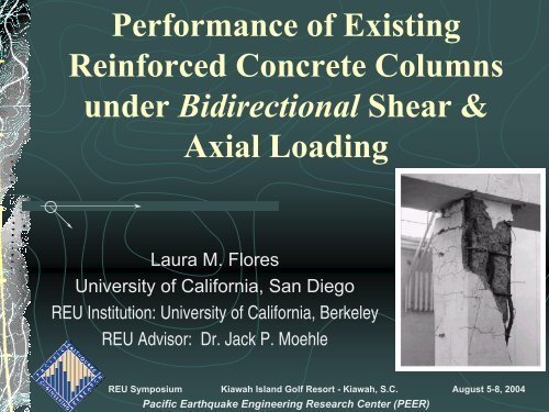
Performance of Existing<br />
<strong>Reinforced</strong> <strong>Concrete</strong> <strong>Columns</strong><br />
under Bidirectional Shear &<br />
Axial Loading<br />
Laura M. Flores<br />
University of California, San Diego<br />
REU Institution: University of California, Berkeley<br />
REU Advisor: Dr. Jack P. Moehle<br />
REU Symposium Kiawah Island Golf Resort - Kiawah, S.C. August 5-8, 2004<br />
Pacific Earthquake Engineering Research Center (PEER)
Outline<br />
Research Background & Project Objectives<br />
Design of Test Setup<br />
RC Column Specimen Material & Geometry<br />
Capacity Models<br />
Flexural, Shear and Axial Capacity<br />
Moment – Curvature Response of Column<br />
Deformation Components<br />
Lateral Deformation – Shear Failure<br />
Axial Deformation<br />
Residual Column Capacity & Damage Progression<br />
Fabrication of RC Column Specimens<br />
Sensitivity Analysis<br />
Ongoing<br />
Acknowledgments
Research Background<br />
Mechanisms leading to the collapse of existing, pre-seismic code<br />
RC frames are NOT well documented.<br />
Shake table tests are currently being conducted at PEER-UCB to<br />
observe & identify the failure components & load redistribution<br />
processes in RC bridge columns & in RC building frames under<br />
seismic & gravity loading.<br />
Identifying mechanisms causing shear failure in RC columns can<br />
be used to develop performance-based seismic design -<br />
strengthen future & existing structures against earthquake<br />
loading<br />
Column shear failure & its effect on the degradation of axial<br />
capacity in a pre-seismic code RC column is the focus of this<br />
project.
PERSONAL:<br />
Project Objectives<br />
To independently conduct research & gain extensive laboratory experience in<br />
the field of structural – earthquake engineering<br />
Opportunity to work with researchers on cutting-edge research and learn about<br />
ongoing studies in seismic design and retrofitting<br />
Opportunity to learn and apply theories of seismic design & analysis to RC<br />
columns under seismic and gravity loads<br />
RESEARCH:<br />
Identify lateral & axial deformation components leading to RC column failure<br />
Compute flexural, shear and axial capacity models of RC column<br />
Design experimental setup allowing bidirectional loading of RC column for<br />
specific loading requirements & under budget<br />
Fabricate RC column specimens based on design specs<br />
Analyze the effect of bidirectional loading on the shear and axial failure of RC<br />
column and compare to predictive capacity models
Simplified Model of RC Column<br />
One-third scale of existing, pre-seismic ACI code<br />
designed RC Column<br />
½ of RC column used in analysis<br />
Free end of column idealized as hinge connection<br />
with a fixed end at base of column
Simplified Model of RC Column (cont.)<br />
M(x)<br />
RC<br />
Col’n<br />
M = 0<br />
(hinge)<br />
M = M MAX<br />
(fixed)<br />
RC<br />
Col’n
Design of Test Setup<br />
Gravity Load<br />
= 10 kips<br />
Actuator / Seismic<br />
Load = 8.3 kips<br />
HINGE<br />
RC<br />
Col’n<br />
FIXED
Design of Test Setup (cont.)<br />
TEST APPARTUS<br />
1'-4 3/8"<br />
(platform<br />
width?)<br />
9"x8" flanged beam 70lb/ft.<br />
S=61.5 cu. in.<br />
1'-5"<br />
4'-6"<br />
6"x3"channel beam<br />
2'-9 7 8 "ACTUATOR<br />
POSITION<br />
A<br />
42.25"<br />
B<br />
C<br />
4" x 5" x 1" pillow<br />
block - pnt.load<br />
1/2" x 1/2" x 10"<br />
hold-in-place<br />
rods(check<br />
height&spacing?)<br />
1'-1 5 8 "<br />
lead ingot-14 bars<br />
110 lb/bar<br />
total wt. 1540 lb.<br />
4" (add<br />
spacing if<br />
needed)<br />
clamp??<br />
(H-structure) safety frame<br />
3"x2" angle iron<br />
welded construction<br />
1/2" concrete<br />
anchor bolts<br />
( ??2 places??)<br />
A<br />
base plate 2 in. thickness<br />
15 in.width and 3 ft. length<br />
FRONT VIEW<br />
CONCRETE<br />
FLOOR<br />
4'-7 7 8 "<br />
SIDE VIEW<br />
SECTION C-C
RC Column Material & Geometry
RC Column Material & Geometry (cont.)
Capacity Models of RC Column<br />
Specimen: Axial Capacity<br />
Axial Capacity of undamaged RC column:<br />
P N = 0.85*f C ’*(A g – A SL ) + f YL* A SL<br />
..where f C ’ concrete compressive strength, A g is the gross<br />
concrete area, A SL is the longitudinal reinforcement area,<br />
f YL is yield strength of longitudinal steel<br />
P N<br />
= 0.85*(3ksi)*[36in 2 -0.884in 2 ] +<br />
(70ksi)*(0.884in 2 )<br />
P N<br />
= 151.43 kips
Capacity Models of RC Column<br />
Specimen: Flexural Capacity<br />
h<br />
ε cu = .003<br />
•<br />
• ε s2<br />
• ε s3<br />
N.A.<br />
.85f C ’<br />
a<br />
T S2<br />
T S1<br />
T S3<br />
C C<br />
T S3<br />
T S2<br />
T S1<br />
•<br />
ε S1 = -00207<br />
C C<br />
M ΣM N<br />
T h/2 = 0 @Balanced Failure (Z=-1)<br />
S3<br />
P N • T -T S3<br />
*[(h/2)-d S3<br />
] - C C<br />
*[(h/2)-(a/2)] + M N<br />
-T S1<br />
*[d S1<br />
-(h/2)]<br />
S2<br />
M<br />
T N<br />
= T S3<br />
*[(h/2)-d S3<br />
] + C C<br />
*[(h/2)-(a/2)] +<br />
S1<br />
T S1<br />
*[d S1<br />
-(h/2)]<br />
..so, M N<br />
=153.3 kip-in
Capacity Models of RC Column<br />
Specimen: Shear Capacity<br />
Total shear capacity of an RC column depends on the shear<br />
capacity of the concrete, V C and the shear capacity carried by<br />
the transverse reinforcement, V ST in the column<br />
V N = (V C + V ST ) = 2*[1+(P/2000*Ag)]*√f C ’*b W *d +<br />
[(4*A ST *f YT *d)/s]<br />
..where A ST<br />
is the transverse reinforcement area, f YT<br />
is yield strength of transverse reinforcement,<br />
d is distance from compression fiber to farthest tensile reinforcement, s is transverse<br />
reinforcement spacing, b W<br />
is the width of column x-section, P is axial load<br />
V N<br />
= 2*[1+(10,000lb/(2000*35.12in 2 ))]*√(3000psi)*(6in)(5.145in) +<br />
(0.01228in 2 )(70,000psi)(5.145in)<br />
V N<br />
= 8.283 kips
Interaction Diagram of RC Column Specimen<br />
The flexural and axial capacity model for RC columns is used to derive an<br />
interaction diagram which relates the axial load column capacity with its<br />
moment capacity at any given time<br />
120<br />
100<br />
Maximum<br />
Axial Load<br />
Zero stress in tensile<br />
reinforcement, Z=0<br />
(nom inal) Axial Load Capacity, Pn (kips)<br />
80<br />
60<br />
40<br />
20<br />
0<br />
0 20 40 60 80 100 120 140 160<br />
-20<br />
Balanced<br />
Failure, Z= -1<br />
COMPRESSION<br />
TENSION<br />
-40<br />
(nominal) Moment Capacity, Mn (kip-in)
Moment-Curvature Response of Shear-Critical RC<br />
Column under Axial & Lateral (Shear) Loading<br />
The flexural and axial capacity model for RC columns is used to derive an interaction<br />
diagram which relates the axial load column capacity with its moment capacity at any<br />
given time<br />
160<br />
M Y =V Y *l<br />
140<br />
120<br />
100<br />
80<br />
60<br />
Moment, M (kip-in)<br />
40<br />
20<br />
0<br />
-7.E-22<br />
1.E-04<br />
3.E-04<br />
4.E-04<br />
5.E-04<br />
7.E-04<br />
8.E-04<br />
9.E-04<br />
1.E-03<br />
1.E-03<br />
1.E-03<br />
1.E-03<br />
2.E-03<br />
2.E-03<br />
2.E-03<br />
2.E-03<br />
2.E-03<br />
2.E-03<br />
2.E-03<br />
3.E-03<br />
3.E-03<br />
3.E-03<br />
3.E-03<br />
3.E-03<br />
3.E-03<br />
3.E-03<br />
3.E-03<br />
4.E-03<br />
4.E-03<br />
Curvature, θ (1/in)
Deformation Components:<br />
Lateral Deflection<br />
Flexure<br />
M<br />
M ∆ FL = [(39in) 2 /6]*(7.6*10 -4 in -1 )<br />
= 0.19266 in
Flexure<br />
Deformation Components:<br />
Lateral Deflection
Deformation Components:<br />
Lateral Deflection<br />
Bar (Bond) Slip<br />
M<br />
M ∆ SL = [(39in)(0.375in)(70,000psi)(7.6*10 -4 in -1 )] /<br />
[8*6*√3000psi]<br />
= 0.2959 in
Deformation Components:<br />
Shear<br />
Lateral Deflection<br />
V<br />
V<br />
∆ SH = [2(113,000lb-in)] / (1.53*10 6 )(29.26in 2 )<br />
= 0.005048 in.
Deformation Components:<br />
Shear<br />
Lateral Deflection
Lateral Yield Deformation of RC column:<br />
Lateral yield deformation (prior to shear failure) of longitudinal<br />
reinforcement in RC column results from 3 components<br />
acting in series:<br />
Flexure, Bar (Bond) Slip, Shear<br />
(∆ LAT ) Y = ∆ Y = ( ∆ FL + ∆ SL + ∆ SH )<br />
(∆ LAT<br />
) Y<br />
= ∆ Y<br />
= (0.19266 in) + (0.2959 in) + (0.005048 in)<br />
= 0.49365 in.<br />
Flexural<br />
displacement,<br />
∆FL<br />
Slip<br />
displacement,<br />
∆SL<br />
Shear<br />
displacement,<br />
∆SH<br />
Yield<br />
displacement,<br />
∆Y<br />
0.19266 in 0.295941 in 0.005048 in 0.49365 in
Deformation Components:<br />
Shear → Axial Failure<br />
! After yielding of longitudinal<br />
reinforcement, column<br />
sustains gravity and lateral<br />
(shear) loads until shear<br />
demand on column exceeds<br />
ultimate??? shear capacity of<br />
column (V>V U ) – shear failure<br />
occurs<br />
! After shear failure occurs in<br />
column, gravity loads are<br />
supported by shear-friction<br />
forces along shear failure<br />
plane – (∆ LAT ) AX occurs<br />
θ<br />
Shear<br />
Failure<br />
Plane
Deformation Components:<br />
Shear → Axial Failure (cont.)<br />
θ<br />
Shear<br />
Failure<br />
Plane
Deformation Components:<br />
Shear → Axial Failure (cont.)<br />
Residual Axial Capacity (after shear failure) of damaged RC<br />
column:<br />
P N = tanθ*[(A ST *f YT *d C )/s]*[(1+µtanθ)/(tanθ-µ)]<br />
..where f YT is yield strength of transverse reinforcement, d C is distance b/w<br />
extreme longitudinal reinforcement., s is transverse reinforcement spacing, θ is<br />
critical crack angle, µ is effective friction coefficient, A ST is transverse<br />
reinforcement area<br />
P N<br />
= [tan65(0.01228in2)(70ksi)(4.5417in) / (4in)]*[(1+(8.28kip/10kip)*tan65) /<br />
(tan65-(8.28kip/10kip))]<br />
= 4.4 kips<br />
!When gravity loads exceed shear-friction forces, axial failure occurs in<br />
column (column loses ALL shear capacity) → total collapse of structure
Deformation Components:<br />
Shear → Axial Failure (cont.)<br />
Axial Failure of<br />
Column<br />
Total Collapse of<br />
Column
Damage Progression in Column – Drift<br />
Capacity Model<br />
Progression of damage in a shear-critical RC column can be<br />
quantified using an empirical drift capacity model based on the<br />
column’s lateral displacement (i.e. ‘drift’)<br />
Drift Ratio at Yielding of<br />
Longitudinal Reinforcement<br />
(∆/L) Y<br />
= 0.00494<br />
Drift Ratio at Shear Failure<br />
(∆/L) SH<br />
= 0.026248<br />
Drift Ratio at Axial Failure<br />
L<br />
(∆/L) AX<br />
= 0.035183<br />
L
Damage Progression in Column – EPP<br />
Backbone Model<br />
Elastic-Perfectly-Plastic (EPP) backbone model approximates the<br />
shear load vs. lateral displacement behavior of shear-critical RC<br />
columns via. a ‘shear-failure surface’<br />
EPP backbone model utilizes the calculated column drift ratios at<br />
yielding, shear & axial failure, as well as the yield moment derived<br />
from the column moment-curvature response to generate the<br />
column’s ‘shear failure surface’ under lateral and gravity loading
Shear-Critical RC column Shear Hysteretic (forcedisplacement)<br />
Response w/ EPP shear-drift backbone<br />
∆ Y<br />
∆ SH<br />
∆ AX<br />
EPP-predicted<br />
shear failure<br />
surface
Fabrication of RC Column Specimens<br />
Column Forms –<br />
plywood, 2x4’s<br />
6”<br />
2’-4 5/8”<br />
RC<br />
Col’n<br />
1’-1 5/8”<br />
1’-10”
Fabrication of RC Column Specimens (cont.)<br />
Steel Cages /<br />
Longitudinal &<br />
Transverse<br />
Reinforcement<br />
– 60 Grade #3 & #5<br />
rebar, tie wires, 1/8”<br />
diameter stirrups
Fabrication of RC Column Specimens (cont.)<br />
Casting of<br />
Column<br />
Specimens<br />
– f C ’ = 3 ksi
Fabrication of RC Column Specimens<br />
(cont.) – Sensitivity Analysis<br />
Sensitivity of RC Column Moment Capacity to Increasing 28-day Compressive Strength of<br />
<strong>Concrete</strong>.<br />
200<br />
180<br />
(nominal) Moment Capacity, Mn (kip-in)<br />
160<br />
140<br />
120<br />
100<br />
80<br />
60<br />
40<br />
fy constant<br />
20<br />
0<br />
1.5 2 2.5 3 3.5 4 4.5<br />
<strong>Concrete</strong> Compressive Strength, fc' (ksi)
Fabrication of RC Column Specimens<br />
(cont.) – Sensitivity Analysis<br />
Sensitivity of RC Column Axial Load Capacity to Increasing 28-day Compressive Strength of<br />
<strong>Concrete</strong>.<br />
70<br />
60<br />
(nominal) Axial Load Capacity, Pn (kips)<br />
50<br />
40<br />
30<br />
20<br />
fy constant<br />
10<br />
0<br />
1.5 2 2.5 3 3.5 4 4.5<br />
<strong>Concrete</strong> Compressive Strength, fc' (ksi)
-Ongoing-<br />
My Research Objectives to be completed:<br />
" Fabrication of experimental setup<br />
" Testing of RC column specimens<br />
" Comparing observed RC column hysteretic response under axial & shear<br />
loading w/ that response predicted by capacity models<br />
Overall Research Objectives to be completed:<br />
" Using results to calibrate existing OpenSees analytical model<br />
that is based on RC structure deformation components &<br />
capacity models<br />
" Using revised OpenSees analytical model to predict hysteretic<br />
response of existing RC building structure (composed of several<br />
column-beam components) to seismic & gravity loading<br />
" Fabrication & testing of large-scale RC building frame<br />
" Additional verification studies of OpenSees analytical model
Acknowledgments<br />
Research conducted as part of the 2004 Pacific Earthquake<br />
Engineering Research Center (PEER) Research Experience for<br />
Undergraduates & funded by the National Science Foundation<br />
Special thanks to my PEER advisor, Professor Jack P. Moehle for<br />
his guidance in the direction of my project and working hard to<br />
secure the funding which made this research experience possible<br />
Thanks to UC Berkeley graduate students, Wassim Michael<br />
Ghannoum & Yoon Bong Shin for their assistance in every aspect<br />
of this project<br />
Thanks to Richmond Field Station – PEER headquarters lab<br />
personnel for their assistance in the design & fabrication of my<br />
experimental setup