The Virtual Motion Controller - Human Interface Technology ...
The Virtual Motion Controller - Human Interface Technology ...
The Virtual Motion Controller - Human Interface Technology ...

Create successful ePaper yourself
Turn your PDF publications into a flip-book with our unique Google optimized e-Paper software.
and down (z-axis) motion into motion through the virtual world. A technique reported by<br />
Iwata (1996) uses a system of special roller skates and a waist-high frame firmly attached<br />
to the floor which surrounds the participant. <strong>Motion</strong> of the participants feet as they push<br />
against the frame are transduced with the special skates and used to drive the motion of the<br />
virtual world.<br />
Given the above requirements, it would seem that the ideal interface would be some type<br />
of 360 degree treadmill. However our analysis of this type of approach leads us to<br />
conclude that this would be difficult and expensive to produce, and may be unsafe in some<br />
situations (to overcome inertia the system must use, and the user must be coupled to,<br />
several horsepower). Furthermore there are less expensive alternatives which could<br />
provide many of the advantages and none of the disadvantages associated with other<br />
techniques. <strong>The</strong> disadvantages include difficulty in maneuvering with a treadmill, the<br />
inability to adopt multiple postures with a stationary unicycle, and the lack of naturalness<br />
when walking on a frictionless surface.<br />
3. <strong>The</strong> concept of sufficient motion<br />
One alternative involves the concept of “sufficient motion.” A sufficient motion simulator<br />
allows enough motion in the real world to create a sense of presence and realism in the<br />
virtual world. In contrast, a 360 degree treadmill would represent a “full motion”<br />
simulator.<br />
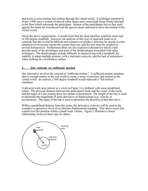
A physical work area (shown as a circle in Figure 1) is defined, with some predefined<br />
center. <strong>The</strong> physical distance between the participant's body and the center of the circle,<br />
and the angle of a line joining those two points is determined. <strong>The</strong> length of the line is used<br />
to determine the magnitude of some derivative of displacement (e.g. velocity or<br />
acceleration). <strong>The</strong> angle of the line is used to determine the direction of that derivative.<br />
Within a predefined distance from the center, the derivative (velocity will be used in the<br />
example) is ignored in favor of an absolute displacement mapping. This allows users fine<br />
control over the position within a small work volume. Figure 2 illustrates a linear<br />
relationship; however there may be others.<br />
body<br />
location<br />
working<br />
area<br />
minimum<br />
distance<br />
center