To Know How - GROHE
To Know How - GROHE
To Know How - GROHE

You also want an ePaper? Increase the reach of your titles
YUMPU automatically turns print PDFs into web optimized ePapers that Google loves.
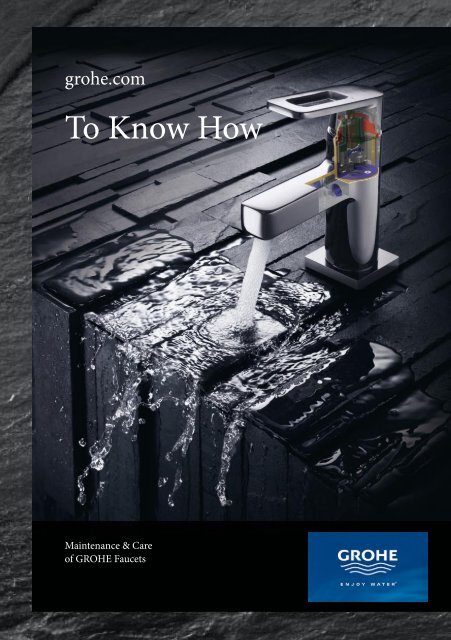
grohe.com<br />
<strong>To</strong> <strong>Know</strong> <strong>How</strong><br />
Maintenance & Care<br />
of <strong>GROHE</strong> Faucets
<strong>To</strong> <strong>Know</strong> <strong>How</strong> - Maintenance & Care of <strong>GROHE</strong> Faucets
12/2008 - Copyright by <strong>GROHE</strong><br />
Grohe Headquarters<br />
Grohe AG<br />
Feldmühleplatz 15<br />
40545 Düsseldorf / Germany<br />
www.grohe.com<br />
Grohe Regional HQ<br />
East Mediterranean<br />
Middle East<br />
Africa<br />
Grome Marketing (Cyprus) Ltd.<br />
P.O. Box 27048, CY-1641 Nicosia, Cyprus<br />
Phone: + 357 - 22 - 46 52 00<br />
Telefax: + 357 - 22 - 37 91 88<br />
info@grome.com<br />
www.grome.com
Dear Grohe customers,<br />
When it comes to maintenance, service or<br />
repair of our fittings, we want to meet your<br />
highest requirements.<br />
This "<strong>To</strong> <strong>Know</strong> <strong>How</strong>" booklet helps you to<br />
identify quickly and effectively the product<br />
type, determine the right spare parts and<br />
generally simplify your work by providing<br />
some practical advice.<br />
Training:<br />
Perfect service and competent action<br />
demand permanent deepening and broadening<br />
of one's knowledge. Therefore a variety<br />
of different training workshops are offered by<br />
<strong>GROHE</strong> throughout the year in order to keep<br />
you up-to-date.<br />
Every training workshop is supported by<br />
animations, cut samples of products, images<br />
and our own in-house technical centres with<br />
test stands in order to give the trainees optimal<br />
preparation for all possible scenarios. We<br />
are always glad to organize a tailor-made training<br />
programme for your company.<br />
2
Working with this book<br />
<strong>Know</strong> What<br />
"<strong>To</strong> <strong>Know</strong> <strong>How</strong>" offers you all the information<br />
necessary for maintenance and repair of<br />
<strong>GROHE</strong> fittings. In this book we have tried<br />
our best to cater for the needs of the specialists<br />
on-site.<br />
Products are documented by picture and<br />
dimensioned drawing. There is a description<br />
of dismantling/installation and related maintenance<br />
works followed by an exploded drawing<br />
with correspondent spare parts list.<br />
At the end of voluminous chapters - i.e. for<br />
technically complex products -<br />
you will find a summary of helpful hints for<br />
product maintenance as well as troubleshooting<br />
tables.<br />
<strong>Know</strong> Where<br />
"<strong>To</strong> <strong>Know</strong> <strong>How</strong>" offers you various possibilities<br />
to find the product you are looking for.<br />
Depending on what information about the<br />
product you require, you can choose one of<br />
the following search options:<br />
If you know the product type and the name<br />
of the line:<br />
Search in the Contents. Here the page numbers<br />
are indicated to show where the description<br />
of the first product of the line starts.<br />
If you know the product type, but are not<br />
aware of the line name or product serial number:<br />
Search in Product Overview at the beginning<br />
of the correspondent chapter. You can identify<br />
the needed product using images shown<br />
and follow the indicated page number.<br />
If you know the product serial number:<br />
Search in the List of Product Numbers, right<br />
after Contents at the beginning of the book<br />
and follow the page number indication.<br />
3
<strong>GROHE</strong> TurboStat®<br />
The revolutionary <strong>GROHE</strong> TurboStat® technology gives you the temperature<br />
you desire in a fraction of a second and maintains it for the<br />
duration of your shower. The new thermostats (Grohtherm 1000,<br />
2000 & 3000) feature the most sophisticated, precision-engineered<br />
cartridges to date. <strong>GROHE</strong> has increased the sensitivity of the internal<br />
thermo element and restructured the waterways. As a result the new<br />
thermostats react to abrupt changes in water pressure two times<br />
faster than before, and are up to nine times more accurate than those<br />
of the leading competitors.<br />
<strong>GROHE</strong> Cool<strong>To</strong>uch®<br />
Thanks to the new <strong>GROHE</strong> Cool<strong>To</strong>uch® the entire outer surface of<br />
the Grohtherm 2000 and 3000 thermostats never exceeds that of your<br />
preferred shower temperature. Now there's no risk of scalding yourself<br />
on a hot chrome surface - a real plus for families with young children.<br />
By redesigning the thermostats to include an innovative cooling<br />
channel and special couplings where the hot water enters the thermostat,<br />
<strong>GROHE</strong> created a barrier between the hot water and the chrome<br />
surface, so it's never too hot to handle.<br />
<strong>GROHE</strong> SilkMove®<br />
Only <strong>GROHE</strong> faucets deliver the unique <strong>GROHE</strong> SilkMove® experience.<br />
From the first touch of the lever you sense the superiority of<br />
the product. With the first movement you feel the sensation of rich<br />
smoothness and solid subtlety. The extra wide operating angle gives<br />
you maximum control to exactly manage the desired flow rate and<br />
temperature. Every silky move conveys value and absolute precision.<br />
The unique TÜV SÜD award-winning <strong>GROHE</strong> SilkMove® feel is<br />
based on superior cartridge technology inside the faucet.<br />
4
Grohe Technology<br />
<strong>GROHE</strong> StarLight®<br />
<strong>GROHE</strong> faucets strike your eyes with an absolutely smooth immaculate<br />
surface and a radiant brilliant shine. The shine intensity stays for<br />
a lifetime thanks to the soil repellent effect and a high resistance to<br />
scratches and tarnish of the <strong>GROHE</strong> StarLight® surface. In essence,<br />
the <strong>GROHE</strong> shine is starlike in its radiance and endurance. Over 70<br />
years of continuous advancement in chromium finishes and the latest<br />
in galvanization equipment guarantee the unique <strong>GROHE</strong> StarLight®<br />
chromium surface finish.<br />
<strong>GROHE</strong> DreamSpray®<br />
All <strong>GROHE</strong> showers incorporate <strong>GROHE</strong> DreamSpray® technology.<br />
This winning formula of quality and innovation creates optimal water<br />
distribution for an unparalleled showering experience. As experts in<br />
water technology, it is our mission to develop superior showers with<br />
outstanding features. <strong>GROHE</strong> DreamSpray® technology is at the<br />
heart of every <strong>GROHE</strong> shower and ensures a lifetime of good looks,<br />
comfort and performance. What this means is also a lifetime of reliability<br />
and maintenance-free operation. Through the decades, <strong>GROHE</strong><br />
has developed products that stand the test of time.<br />
<strong>GROHE</strong> Whisper®<br />
For peace, comfort and design freedom, our concealed cisterns feature<br />
<strong>GROHE</strong> Whisper® technology. This is achieved thanks to decoupled<br />
pipe supports, which prevent any sound being transferred to the<br />
structure of the building when the water is released from the cistern<br />
to the bowl. Increasingly, designers and fitters want more freedom in<br />
where they can locate the WC. With <strong>GROHE</strong> Whisper® there is no<br />
need to worry about excessive flushing noise, allowing the WC to be<br />
located without fear of disturbing others.<br />
5
Product Overview. . . . . . . . . . . . . . . . . . . . . . . . . . . . . . . . . . . . . . . . . . . . . . . . . . . . 8<br />
Single-lever mixer Product overview<br />
Unterputzkörper . . . . . . . . . . . . . . . . . . . . . . . . . . . . . . . E 9<br />
Allure . . . . . . . . . . . . . . . . . . . . . . . . . . . . . . . . . . . . . . . . E 12<br />
Atrio. . . . . . . . . . . . . . . . . . . . . . . . . . . . . . . . . . . . . . . . . E 20<br />
Ectos . . . . . . . . . . . . . . . . . . . . . . . . . . . . . . . . . . . . . . . . E 28<br />
Tenso. . . . . . . . . . . . . . . . . . . . . . . . . . . . . . . . . . . . . . . . E 24<br />
Taron . . . . . . . . . . . . . . . . . . . . . . . . . . . . . . . . . . . . . . . . E 34<br />
Chiara . . . . . . . . . . . . . . . . . . . . . . . . . . . . . . . . . . . . . . . E 38<br />
Lineare. . . . . . . . . . . . . . . . . . . . . . . . . . . . . . . . . . . . . . . E 44<br />
Europlus . . . . . . . . . . . . . . . . . . . . . . . . . . . . . . . . . . . . . E 50<br />
Eurowing . . . . . . . . . . . . . . . . . . . . . . . . . . . . . . . . . . . . . E 58<br />
Eurofresh. . . . . . . . . . . . . . . . . . . . . . . . . . . . . . . . . . . . . E 62<br />
Eurodisc. . . . . . . . . . . . . . . . . . . . . . . . . . . . . . . . . . . . . . E 66<br />
Essence. . . . . . . . . . . . . . . . . . . . . . . . . . . . . . . . . . . . . . E 74<br />
Concetto . . . . . . . . . . . . . . . . . . . . . . . . . . . . . . . . . . . . . E 78<br />
Eurostyle . . . . . . . . . . . . . . . . . . . . . . . . . . . . . . . . . . . . . E 82<br />
Eurosmart . . . . . . . . . . . . . . . . . . . . . . . . . . . . . . . . . . . . E 88<br />
Euroeco . . . . . . . . . . . . . . . . . . . . . . . . . . . . . . . . . . . . . . E 98<br />
Two handle Fittings Product overview . . . . . . . . . . . . . . . . . . . . . . . . . . . . . . Z 2<br />
Allure . . . . . . . . . . . . . . . . . . . . . . . . . . . . . . . . . . . . . . . . Z 6<br />
Atrio. . . . . . . . . . . . . . . . . . . . . . . . . . . . . . . . . . . . . . . . . Z 8<br />
Aria . . . . . . . . . . . . . . . . . . . . . . . . . . . . . . . . . . . . . . . . . Z 14<br />
Sentosa . . . . . . . . . . . . . . . . . . . . . . . . . . . . . . . . . . . . . . Z 18<br />
Sinfonia . . . . . . . . . . . . . . . . . . . . . . . . . . . . . . . . . . . . . . Z 22<br />
Florida . . . . . . . . . . . . . . . . . . . . . . . . . . . . . . . . . . . . . . . Z 24<br />
Costa . . . . . . . . . . . . . . . . . . . . . . . . . . . . . . . . . . . . . . . . Z 26<br />
Atlanta . . . . . . . . . . . . . . . . . . . . . . . . . . . . . . . . . . . . . . . Z 29<br />
Thermostats Product overview . . . . . . . . . . . . . . . . . . . . . . . . . . . . . . T 2<br />
Grohtherm 1000 . . . . . . . . . . . . . . . . . . . . . . . . . . . . . . . T 6<br />
Grohtherm 2000 . . . . . . . . . . . . . . . . . . . . . . . . . . . . . . . T 14<br />
Grohtherm 3000 . . . . . . . . . . . . . . . . . . . . . . . . . . . . . . . T 20<br />
Automatic 2000 . . . . . . . . . . . . . . . . . . . . . . . . . . . . . . . . T 28<br />
Euroeco Safety Mixer . . . . . . . . . . . . . . . . . . . . . . . . . . . T 32<br />
Grohtherm XL . . . . . . . . . . . . . . . . . . . . . . . . . . . . . . . . . T 34<br />
Tenso. . . . . . . . . . . . . . . . . . . . . . . . . . . . . . . . . . . . . . . . T 36<br />
Settings (Aquadimmer, temperatur) . . . . . . . . . . . . . . . . T 38<br />
6
Index of contents<br />
Special Fittings Product overview . . . . . . . . . . . . . . . . . . . . . . . . . . . . . . S 2<br />
Accessories kit . . . . . . . . . . . . . . . . . . . . . . . . . . . . . . . . S 3<br />
Europlus E . . . . . . . . . . . . . . . . . . . . . . . . . . . . . . . . . . . . S 4<br />
Euroeco Special. . . . . . . . . . . . . . . . . . . . . . . . . . . . . . . . S 6<br />
Eurodisc SE . . . . . . . . . . . . . . . . . . . . . . . . . . . . . . . . . . . S 8<br />
Controecon . . . . . . . . . . . . . . . . . . . . . . . . . . . . . . . . . . . S 12<br />
Contromix Surf . . . . . . . . . . . . . . . . . . . . . . . . . . . . . . . . S 14<br />
Contropress. . . . . . . . . . . . . . . . . . . . . . . . . . . . . . . . . . . S 16<br />
Adjustments, problem-cause-remedy tables . . . . . . . . . S 18<br />
Kitchen Fittings Product overview . . . . . . . . . . . . . . . . . . . . . . . . . . . . . . K 2<br />
Atrio. . . . . . . . . . . . . . . . . . . . . . . . . . . . . . . . . . . . . . . . . K 6<br />
K4 . . . . . . . . . . . . . . . . . . . . . . . . . . . . . . . . . . . . . . . . . . K 8<br />
Zedra . . . . . . . . . . . . . . . . . . . . . . . . . . . . . . . . . . . . . . . . K 10<br />
Minta . . . . . . . . . . . . . . . . . . . . . . . . . . . . . . . . . . . . . . . . K 12<br />
Essence. . . . . . . . . . . . . . . . . . . . . . . . . . . . . . . . . . . . . . K 14<br />
Alira . . . . . . . . . . . . . . . . . . . . . . . . . . . . . . . . . . . . . . . . . K 16<br />
Europlus . . . . . . . . . . . . . . . . . . . . . . . . . . . . . . . . . . . . . K 18<br />
Eurodisc. . . . . . . . . . . . . . . . . . . . . . . . . . . . . . . . . . . . . . K 20<br />
Eurowing . . . . . . . . . . . . . . . . . . . . . . . . . . . . . . . . . . . . . K 12<br />
Eurostyle . . . . . . . . . . . . . . . . . . . . . . . . . . . . . . . . . . . . . K 22<br />
Eurosmart . . . . . . . . . . . . . . . . . . . . . . . . . . . . . . . . . . . . K 24<br />
Costa . . . . . . . . . . . . . . . . . . . . . . . . . . . . . . . . . . . . . . . . K 26<br />
Atlanta . . . . . . . . . . . . . . . . . . . . . . . . . . . . . . . . . . . . . . . K 26<br />
Supra . . . . . . . . . . . . . . . . . . . . . . . . . . . . . . . . . . . . . . . . K 30<br />
Shower Systems Product overview . . . . . . . . . . . . . . . . . . . . . . . . . . . . . . B 2<br />
Aquatower 1000 . . . . . . . . . . . . . . . . . . . . . . . . . . . . . . . B 4<br />
Aquatower 2000 . . . . . . . . . . . . . . . . . . . . . . . . . . . . . . . B 6<br />
Aquatower 3000 . . . . . . . . . . . . . . . . . . . . . . . . . . . . . . . B 8<br />
Freehander ® . . . . . . . . . . . . . . . . . . . . . . . . . . . . . . . . . . . B 10<br />
Adjustments . . . . . . . . . . . . . . . . . . . . . . . . . . . . . . . . . . B 12<br />
7
Index of contents<br />
Sanitary systems Product overview . . . . . . . . . . . . . . . . . . . . . . . . . . . . . . D 2<br />
WC electronic . . . . . . . . . . . . . . . . . . . . . . . . . . . . . . . . . D 6<br />
Radar electronic. . . . . . . . . . . . . . . . . . . . . . . . . . . . . . . . D 8<br />
Urinal flush valves . . . . . . . . . . . . . . . . . . . . . . . . . . . . . . D 14<br />
WC flush valves . . . . . . . . . . . . . . . . . . . . . . . . . . . . . . . D 16<br />
Concealed / exposed flushing cisterns . . . . . . . . . . . . . . D 22<br />
Flushing mechanism . . . . . . . . . . . . . . . . . . . . . . . . . . . . D 32<br />
Uniset . . . . . . . . . . . . . . . . . . . . . . . . . . . . . . . . . . . . . . . D 35<br />
Rapid SL . . . . . . . . . . . . . . . . . . . . . . . . . . . . . . . . . . . . . D 40<br />
Adjustments . . . . . . . . . . . . . . . . . . . . . . . . . . . . . . . . . . D 18<br />
Concealed bodies Product overview . . . . . . . . . . . . . . . . . . . . . . . . . . . . . . UP 2<br />
Grohe Rapido . . . . . . . . . . . . . . . . . . . . . . . . . . . . . . . . . UP 4<br />
Single lever mixer for concealed installation. . . . . . . . . . UP 6<br />
Thermostats for shower and bath. . . . . . . . . . . . . . . . . . UP 8<br />
8
Product Overview<br />
Prod.No.<br />
Page<br />
Prod.No.<br />
Page<br />
Prod.No.<br />
Page<br />
19<br />
19050000 E 32<br />
19051000 E 32<br />
19155000 E 42<br />
19156000 E 42<br />
19198000 E 64<br />
19199000 E 64<br />
19236000 T 12<br />
19285000 E 76<br />
19286000 E 76<br />
19287001 E 22<br />
19289000 E 30<br />
19296000 E 48<br />
19297000 E 48<br />
19309000 E 16<br />
19315000 E 18<br />
19316000 Z 6<br />
19317000 E 18<br />
19345000 E 80<br />
19346000 E 80<br />
19352000 T 18<br />
19354000 T 16<br />
19355000 T 16<br />
19356000 T 26<br />
19358000 T 26<br />
19359000 T 26<br />
19450001 E 92<br />
19451001 E 92<br />
19506000 E 86<br />
19506001 E 84<br />
19507000 E 86<br />
19507001 E 84<br />
19516000 E 100<br />
19517000 E 100<br />
19520000 E 60<br />
19521000 E 60<br />
19532IP0 E 36<br />
19533IP0 E 36<br />
19536000 E 56<br />
19536001 E 52<br />
19537000 E 56<br />
19537001 E 52<br />
19546IP0 E 26<br />
19547IP0 E 26<br />
19548000 E 72<br />
19548001 E 68<br />
19549000 E 72<br />
19549001 E 68<br />
19656000 T 8<br />
19663000 T 22<br />
19664000 T 22<br />
19665000 T 22<br />
20<br />
20000000 Z 10<br />
20008000 Z 10<br />
20143000 Z 6<br />
20144000 Z 6<br />
20147000 Z 16<br />
21<br />
21012000 Z 22<br />
21014000 Z 22<br />
21019000 Z 8<br />
21044000 Z 8<br />
21090000 Z 14<br />
21091000 Z 14<br />
21105000 Z 18<br />
21106000 Z 18<br />
21217000 Z 29<br />
21242000 Z 29<br />
21375000 Z 26<br />
24<br />
24003000 Z 22<br />
24027000 Z 8<br />
24030000 Z 14<br />
24407000 Z 20<br />
24610000 Z 24<br />
25<br />
25007000 Z 18<br />
25010000 Z 12<br />
25030000 Z 23<br />
25081000 Z 16<br />
25158000 Z 29<br />
25450000 Z 27<br />
25452000 Z 27<br />
25610000 Z 24<br />
26<br />
26000000 Z 23<br />
26003000 Z 12<br />
26008000 Z 16<br />
26251000 Z 30<br />
26330000 Z 28<br />
26347000 Z 21<br />
27<br />
27004000 B 11<br />
27015000 B 4<br />
27017000 B 6<br />
27058000 B 10<br />
27202000 B 8<br />
31<br />
31000000 K 6<br />
31139000 K 28<br />
31144000 K 29<br />
31191000 K 26<br />
31192000 K 26<br />
31426000 K 31<br />
31812000 K 27<br />
31819000 K 30<br />
32<br />
32003001 K 6<br />
32105000 K 14<br />
32108001 E 20<br />
32109000 E 44<br />
32114000 E 44<br />
32144000 E 12<br />
32146000 E 12<br />
32147000 E 12<br />
32148000 E 14<br />
32148000 E 14<br />
32168000 K 12<br />
32171000 K 14<br />
32202000 E 78<br />
32208000 E 78<br />
32210000 E 78<br />
32211000 E 78<br />
32250000 E 44<br />
32303000 E 40<br />
32304000 E 40<br />
32306000 E 40<br />
32390000 E 62<br />
32396000 E 62<br />
32398000 E 62<br />
32401000 E 62<br />
9
Prod.No.<br />
Page<br />
Prod.No.<br />
Page<br />
Prod.No.<br />
Page<br />
32427000 E 28<br />
32457000 E 20<br />
32462000 K 10<br />
32482001 K 24<br />
32488000 K 12<br />
32917000 K 12<br />
32918000 K 12<br />
32925001 E 88<br />
32929001 E 88<br />
32997SD0 K 16<br />
32998SD0 K 16<br />
33<br />
33001000 E 38<br />
33085000 E 58<br />
33118000 S 6<br />
33126000 S 6<br />
33131000 E 98<br />
33133IP0 E 34<br />
33134IP0 E 34<br />
33153000 E 54<br />
33153001 E 50<br />
33155000 E 54<br />
33180IP0 E 24<br />
33183001 E 66<br />
33190000 E 70<br />
33190001 E 66<br />
33202001 K 24<br />
33203000 E 98<br />
33227IP0 E 34<br />
33237000 E 58<br />
33241000 E 54<br />
33241001 E 50<br />
33242000 E 54<br />
33244000 E 70<br />
33244001 E 66<br />
33265000 E 94<br />
33265001 E 88<br />
33268000 E 94<br />
33281000 K 24<br />
33300000 E 96<br />
33300001 E 90<br />
33334001 K 20<br />
33347000 E 28<br />
33348000 E 28<br />
33349000 E 30<br />
33390001 E 66<br />
10<br />
33391000 E 70<br />
33405000 E 98<br />
33418000 E 38<br />
33468000 E 58<br />
33524000 E 34<br />
33532000 E 74<br />
33539000 E 54<br />
33552001 E 82<br />
33553001 E 50<br />
33555000 E 96<br />
33555001 E 90<br />
33558001 E 82<br />
33565001 E 82<br />
33591001 E 82<br />
33603000 E 74<br />
33614000 E 86<br />
33624000 E 74<br />
33707000 K 10<br />
33708000 K 10<br />
33764SD0 K 10<br />
33770000 K 20<br />
33772001 K 20<br />
33782000 K 8<br />
33786000 K 8<br />
33848000 E 44<br />
33849000 E 46<br />
33865000 E 46<br />
33930000 K 18<br />
33933000 K 18<br />
33963000 UP 6<br />
33964000 UP 7<br />
33975000 K 22<br />
33976000 K 22<br />
33977001 K 22<br />
34<br />
34018000 T 32<br />
34027000 T 36<br />
34100000 UP 8<br />
34103000 UP 9<br />
34143000 T 10<br />
34155000 T 10<br />
34169000 T 14<br />
34174000 T 14<br />
34179000 T 24<br />
34185000 T 24<br />
34211000 UP 11<br />
34212000 UP 12<br />
34213000 UP 13<br />
34214000 UP 14<br />
34334000 T 6<br />
34365000 T 30<br />
34367000 T 20<br />
34450000 T 28<br />
34624000 T 6<br />
34679000 T 20<br />
34692000 T 28<br />
34971000 UP 10<br />
34<br />
35085000 T 34<br />
35500000 UP 4<br />
35501000 UP 5<br />
34<br />
36100000 S 12<br />
36109000 S 14<br />
36121000 S 14<br />
36173000 S 16<br />
36176000 S 16<br />
36191000 S 17<br />
36207000 S 4<br />
36233000 S 8<br />
36236000 S 4<br />
36244000 S 10<br />
37<br />
37000000 D 13<br />
37017000 D 14<br />
37021000 D 14<br />
37049000 D 26<br />
37050000 D 27<br />
37071SH0 D 22<br />
37078000 D 33<br />
37092000 D 32<br />
37139000 D 16<br />
37144000 D 18<br />
37147IK0 D 18<br />
37153000 D 20<br />
37355000 D 23<br />
37578000 D 39<br />
37594000 D 30<br />
37713000 D 10<br />
37749000 D 8
Product Overview<br />
Prod.No.<br />
Page<br />
Prod.No. Page Prod.No. Page<br />
37750000 D 8<br />
38<br />
38372000 D 23<br />
38386000 D 12<br />
38393SD0 D 6<br />
38415000 D 38<br />
38421000 D 29<br />
38422000 D 28<br />
38514000 D 43<br />
38519000 D 42<br />
38526000 D 41<br />
38528000 D 40<br />
38642000 D 35<br />
38661000 D 24<br />
38696000 D 35<br />
38697000 D 24<br />
38698SD0 D 6<br />
38702000 D 36<br />
38729000 D 37<br />
38863000 D 31<br />
42<br />
42297PI0 D 34<br />
11
Caring for Grohe Fittings<br />
Caring for Grohe Fittings<br />
Fittings need care to stay perfect for<br />
longer.<br />
Due to calciferous water and the use of normal<br />
care products like soap or<br />
washing liquids, even quality products might<br />
lose their initial shine.<br />
Therefore, please follow the below care hints<br />
carefully, since surface and substance damages<br />
are not subject to guarantee.<br />
Do not use any scrubs or abrasive sponges.<br />
We also do not recommend using solvents,<br />
acid-based detergents, lime-scale removers,<br />
household vinegar and cleansers with acetic<br />
acid. They affect the surface and the fittings<br />
become dull and scratched. As the ingredients<br />
of commercially available detergents<br />
are changed often, we cannot guarantee that<br />
they will properly maintain our products.<br />
Grohclean.<br />
The environmentally safe fittings and bath<br />
cleanser.<br />
Grohclean (order-number 45939) removes<br />
lime-scale and water stains, dirt, grease and<br />
soap residues in kitchens, bathrooms or<br />
toilets.<br />
Grohclean is a chemical composition specially<br />
designed to gently care for <strong>GROHE</strong><br />
products without damaging their surface.<br />
Use it for cleaning fittings, accessories, bathtubs,<br />
ceramics, shower partitions and tiles.<br />
Do not apply Grohclean to marble, lime and<br />
cement based substances and some enamel<br />
types. If you have any doubts, try it on a<br />
small part of the surface to test.<br />
Grohclean contains citric acid and tensides,<br />
which are to 90% biologically degradable.<br />
Wipe the fittings with a wet cloth<br />
with just a bit of soap added. Then rinse and<br />
wipe to dry. Lime-scale stains can be avoided<br />
if you wipe-dry the fitting after each use.<br />
If you still see lime-scale stains appearing,<br />
remove them with Grohclean, our environmentally<br />
safe cleanser.<br />
12
Single-lever Mixer<br />
Single-lever Mixer
Allure<br />
E 12 E 12 E 12 E 14<br />
Atrio<br />
E 14 E 16 E 18 E 18<br />
Ectos<br />
E 20 E 20 E 22<br />
E 24 E 26 E 26<br />
E 2
Product Overview<br />
Tenso<br />
Single-lever Mixer<br />
E 28 E 28 E 28<br />
Taron<br />
E 30 E 30 E 32 E 32<br />
E 34 E 34 E 34 E 34<br />
E 36 E 36<br />
E 3
Chiara<br />
E 38 E 38<br />
E 40 E 40 E 40<br />
Lineare<br />
E 42 E 42<br />
E 44 E 44 E 44 E 44<br />
E 4
Product Overview<br />
Single-lever Mixer<br />
Europlus<br />
E 46 E 46 E 48 E 48<br />
E 50 E 50 E 50<br />
E 52 E 52<br />
E 54 E 54 E 54 E 54<br />
E 5
Eurowing<br />
E 54 E 56 E 56<br />
E 58 E 58 E 58<br />
Eurofresh<br />
E 60 E 60<br />
E 62 E 62 E 62 E 62<br />
E 6
Product Overview<br />
Single-lever Mixer<br />
Eurodisc<br />
E 64 E 64<br />
E 66 E 66 E 66 E 66<br />
E 68 E 68 E 70 E 70<br />
E 70 E 72 E 72<br />
E 7
Essence<br />
E 74 E 74 E 74<br />
Concetto<br />
E 76 E 76<br />
E 78 E 78 E 78 E 78<br />
E 80 E 80<br />
E 8
Product Overview<br />
Eurostyle<br />
Single-lever Mixer<br />
E 82 E 82 E 82 E 82<br />
E 84 E 84 E 86 E 86<br />
Eurosmart<br />
E 86<br />
E 88 E 88 E 88 E 90<br />
E 9
E 90 E 92 92<br />
Euroeco<br />
E 94 E 94 E 96 E 96<br />
E 98 E 98 E 98<br />
E 100 E 100<br />
E 10
Notes<br />
Single-lever Mixer<br />
E 11
Single-lever basin mixer 32 146<br />
and variants 32 144<br />
Maintenance instructions<br />
Shut off hot and cold water supply!<br />
Please perform disassembly in specified order.Assemble in reverse order.<br />
Single-lever bidet mixer 32 147<br />
Lever:<br />
1. Lever out plug.<br />
2. Unscrew and remove set screw using a<br />
3mm allen key.<br />
3. Pull off lever.<br />
Cartridge<br />
1. Pull off cap.<br />
2. Unscrew screw coupling using a 27mm spanner.<br />
3. Replace complete cartridge.<br />
Observe the correct installation position!<br />
Installation instruction:: Ensure that the cartridge seals<br />
engage in the grooves on the housing and the locating<br />
pins at the base of the cartridge slot into the holes in the<br />
housing.<br />
Replace screw coupling and tighten.<br />
E 12
Allure<br />
32 146<br />
32 147<br />
Single-lever Mixer<br />
Pos. Description Ref.-No.<br />
1 Lever 46610<br />
2 Cap 46581<br />
3 Fitting ring 07419<br />
4 Cartridge 46580<br />
5 Pop-up rod 10769<br />
6 Shank fastening assembly 46249<br />
7 Waste fitting 28915<br />
7.1 Plug 45210<br />
8 Dirt strainer 46625<br />
* Availability on demand<br />
Pos. Description Ref.-No.<br />
1 Lever 46610<br />
2 Cap 46581<br />
3 Fitting ring 07419<br />
4 Cartridge 46580<br />
5 Pop-up rod 10769<br />
6 Mousseur 13989<br />
7 Shank fastening assembly 46249<br />
8 Waste fitting 28915<br />
8.1 Plug 45210<br />
E 13
Single-lever bath mixer 32 148 Single-lever shower mixer 32 149<br />
Maintenance instructions<br />
Shut off hot and cold water supply!<br />
Please perform disassembly in specified order. Assemble in reverse order.<br />
Lever:<br />
1. Lever out plug.<br />
2. Unscrew and remove set screw using a<br />
3mm allen key.<br />
3. Pull off lever.<br />
Cartridge<br />
1. Screw off cap.<br />
2. Loosen screws and remove complete cartridge.<br />
3. Replace complete cartridge.<br />
Observe the correct installation position!<br />
Installation instruction: Ensure that the cartridge seals<br />
engage in the grooves on the housing.<br />
Replace screws and tighten evenly and alternately.<br />
E 14
Allure<br />
32 148<br />
32 149<br />
Single-lever Mixer<br />
Pos. Description Ref.-No<br />
1 Lever 46609<br />
2 Cap 46584<br />
3 Cartridge 46048<br />
4 Diverter knob 46585<br />
5 Diverter 08915<br />
6 Bulkhead union 12088<br />
6.1 Seal Ø45 x Ø3 00444<br />
7 Fastening set 46381<br />
8 Non-return valve 08565<br />
Special accessories:<br />
9 Temperature limiter 46375<br />
* Availability on demand<br />
Pos. Description Ref.-No<br />
1 Lever 46609<br />
2 Cap 46584<br />
3 Cartridge 46048<br />
4 Non-return valve 08565<br />
5 Bulkhead union 12088<br />
5.1 Seal Ø45 x Ø3 00444<br />
6 Fastening set 46381<br />
Special accessories:<br />
7 Temperature limiter 46375<br />
E 15
2-hole basin mixer 19 309<br />
Maintenance instructions<br />
Shut off hot and cold water supply!<br />
Please perform disassembly in specified order. Assemble in reverse order.<br />
Lever:<br />
1. Lever out plug.<br />
2. Unscrew and remove set screw using a<br />
3mm allen key.<br />
3. Pull off lever.<br />
Cartridge<br />
1. Pull off cap.<br />
2. Loosen screws and remove complete cartridge.<br />
3. Replace complete cartridge.<br />
Observe the correct installation position!<br />
Installation instruction: Ensure that the cartridge seals<br />
engage in the grooves on the housing.<br />
Replace screws and tighten evenly and alternately.<br />
E 16
Allure<br />
19 309<br />
Single-lever Mixer<br />
Pos. Description Ref.-No Pos. Description Ref.-No<br />
1 Lever 46609<br />
Special accessories:<br />
2 Cap 09038 4 Temperature limiter 46375<br />
3 Dirt strainer 46625 5 Extension-set 1/2", 25 mm 46191<br />
* Availability on demand E 17
Single-lever bath mixer 19 315 Single-lever bidet mixer 19 317<br />
Maintenance instructions<br />
Shut off hot and cold water supply!<br />
Please perform disassembly in specified order. Assemble in reverse order.<br />
Lever<br />
1. Lever out plug.<br />
2. Unscrew and remove set screw using a 3mm allen<br />
key.<br />
3. Pull off lever.<br />
Escutcheon (Fig. left):<br />
1. Remove escutcheon as illustrated.<br />
2. Unscrew and remove screws and remove escutcheon<br />
mounting bracket.<br />
3. Screw off cap.<br />
Cartridge (Fig. right):<br />
1. Loosen screws and remove cartridge.<br />
2. Replace complete cartridge.<br />
Observe the correct installation position!<br />
Installation instruction:<br />
Ensure that the cartridge seals engage in the grooves on<br />
the housing.<br />
Replace screws and tighten evenly and alternately.<br />
Diverter<br />
1. Unscrew and remove diverter.<br />
2. Hold pushbutton using rubber protected pliers, pull out<br />
diverter piston and unscrew and remove diverter spind<br />
le from the diverter housing using a 4mm open-ended<br />
spanner.<br />
E 18
Allure<br />
19 315<br />
Single-lever Mixer<br />
19 317<br />
Pos. Description Ref.-No<br />
1 Lever 46609<br />
2 Escutcheon 46614<br />
3 Cap 09038<br />
4 Diverter 46058<br />
4.1 Diverter knob 46008<br />
Special accessories:<br />
5 Temperature limiter 46375<br />
6 Extension-set 1/2", 25 mm 46191<br />
7 Extension-set, 50 mm 46343<br />
* Availability on demand<br />
Pos. Description Ref.-No<br />
1 Lever 46609<br />
2 Escutcheon 46613<br />
3 Cap 09038<br />
Special accessories:<br />
4 Temperature limiter 46375<br />
5 Extension-set 1/2", 25 mm 46191<br />
6 Extension-set, 50 mm 46343<br />
E 19
Single-lever basin mixer 32 457 Single-lever bidet mixer 32 108 001<br />
Maintenance instructions<br />
Shut off hot and cold water supply!<br />
Please perform disassembly in specified order. Assemble in reverse order.<br />
Lever:<br />
1. Pull off cap.<br />
2. Unscrew and remove screw and pull off lever.<br />
Cartridge<br />
1. Pull off cap.<br />
2. Unscrew screw coupling using a 32mm spanner.<br />
3. Replace complete cartridge.<br />
Observe the correct installation position!<br />
Installation instruction:: Ensure that the cartridge seals<br />
engage in the grooves on the housing and the locating<br />
pins at the base of the cartridge slot into the holes in the<br />
housing.<br />
Replace screw coupling and tighten.<br />
E 20
Atrio<br />
32 457<br />
32 108 001<br />
Single-lever Mixer<br />
Pos. Description Ref.-No.<br />
1 Lever 46102<br />
2 Cap 46116<br />
3 Ring 04456<br />
4 Cartridge 46374<br />
5 Outlet 13170<br />
5.1 Safety ring 08065<br />
5.2 Sealing washer Ø13,5 x Ø2,75 01285<br />
5.3 Flow straightener 13935<br />
6 Cover cap 08102<br />
7 Pop-up rod 06575<br />
8 Shank fastening assembly 46249<br />
9 Waste fitting 28915<br />
9.1 Plug 45210<br />
* Availability on demand<br />
Pos. Description Ref.-No.<br />
1 lever 46633<br />
2 Cap 46581<br />
3 Fitting ring 07419<br />
4 Cartridge 46580<br />
5 Mousseur 06574<br />
6 Pop-up rod 06575<br />
7 Shank fastening assembly 46249<br />
8 Waste fitting 28915<br />
8.1 Plug 45210<br />
E 21
2-hole basin mixer 19 287 001<br />
Maintenance instructions<br />
Shut off hot and cold water supply!<br />
Please perform disassembly in specified order. Assemble in reverse order.<br />
Lever:<br />
1. Lever out plug.<br />
2. Unscrew and remove set screw using a 3mm allen<br />
key.<br />
3. Pull off lever.<br />
Cartridge<br />
1. Pull off cap.<br />
2. Loosen screws and remove complete cartridge.<br />
3. Replace complete cartridge.<br />
Observe the correct installation position!<br />
Installation instruction: Ensure that the cartridge seals<br />
engage in the grooves on the housing.<br />
Replace screws and tighten evenly and alternately.<br />
E 22
Atrio<br />
19 287 001<br />
Single-lever Mixer<br />
Pos. Description Ref.-No.<br />
1 Lever 46635<br />
2 Mousseur 06574<br />
* Availability on demand<br />
Pos. Description Ref.-No.<br />
Special accessories:<br />
3 Extension 46627<br />
E 23
Single-lever basin mixer<br />
33 180 IP<br />
Maintenance instructions<br />
Shut off hot and cold water supply!<br />
Please perform disassembly in specified order. Assemble in reverse order.<br />
Lever:<br />
1. Lever out plug.<br />
2. Unscrew and remove set screw using a 3mm allen<br />
key.<br />
3. Pull off lever.<br />
Cartridge:<br />
1. Pull off cap.<br />
2. Unscrew screw coupling using a 32mm spanner.<br />
3. Replace complete cartridge.<br />
Observe the correct installation position!<br />
Installation instruction: Ensure that the cartridge seals<br />
engage in the grooves on the housing and the locating<br />
pins at the base of the cartridge slot into the holes in the<br />
housing.<br />
Replace screw coupling and tighten.<br />
E 24
Ectos<br />
33 180 IP<br />
Single-lever Mixer<br />
Pos. Description Ref.-No.<br />
1 Lever 46176<br />
1.1 Fastening set 46177 *<br />
2 Cap 46182 *<br />
2.1 Sealing washer 05915 *<br />
3 Ring 03425 *<br />
4 Cartridge 46374<br />
5 Pop-up rod 46189<br />
6 Shank fastening assembly 46122<br />
7 Compensation ring 03435<br />
8 Mousseur 13929<br />
8.1 Repl.kit f.Mousseur M22x1 and M24x1 45002*<br />
9 Waste set 1 1/4" 28910<br />
9.1 Plug for waste set 1 1/4" 07182<br />
9.1.1 Seal 05065<br />
9.2 Ball rod 07052<br />
* Availability on demand<br />
Pos. Description Ref.-No.<br />
Special accessories:<br />
10 Temperature limiter 46375<br />
11 Support plate 05334<br />
E 25
Single-lever bath mixer 19 547 IP Single-lever shower mixer 19 546 IP<br />
Maintenance instructions<br />
Shut off hot and cold water supply!<br />
Please perform disassembly in specified order. Assemble in reverse order.<br />
Lever:<br />
1. Lever out plug.<br />
2. Unscrew and remove set screw using a 3mm allen<br />
key.<br />
3. Pull off lever.<br />
Excutcheon (Fig. left):<br />
1. Remove escutcheon as illustrated.<br />
2. Unscrew and remove screws and remove escutcheon<br />
mounting bracket.<br />
3. Screw off cap.<br />
Cartridge (Fig. right):<br />
1. Loosen screws and remove cartridge.<br />
2. Replace complete cartridge.<br />
Observe the correct installation position!<br />
Installation instruction:<br />
Ensure that the cartridge seals engage in the grooves on<br />
the housing.<br />
Replace screws and tighten evenly and alternately.<br />
Diverter<br />
1. Unscrew and remove diverter.<br />
2. Hold pushbutton using rubber protected pliers, pull out<br />
diverter piston and unscrew and remove diverter<br />
spindle from the diverter housing using a 4mm openended<br />
spanner.<br />
E 26
Ectos<br />
19 547 IP<br />
Single-lever Mixer<br />
19 546 IP<br />
Pos. Description Ref.-No.<br />
1 Lever 46176<br />
1.1 Fastening set 46177 *<br />
2 Escutcheon 46178 *<br />
2.1 Screws 47460 *<br />
3 Cap 02693<br />
4 Diverter 46133<br />
4.1 Sealing washer Ø6 x Ø2 01283<br />
5 Diverter knob 46391<br />
Special accessories:<br />
6 Temperature limiter 46308<br />
7 Extension-set 1/2", 25 mm 46191<br />
8 Extension-set, 50 mm 46343<br />
* Availability on demand<br />
Pos. Description Ref.-No.<br />
1 Lever 46176<br />
1.1 Fastening set 46177 *<br />
2 Escutcheon 46181 *<br />
2.1 Screws 47460 *<br />
3 Cap 02693<br />
Special accessories:<br />
4 Temperature limiter 46308<br />
5 Extension-set 1/2", 25 mm 46191<br />
6 Extension-set, 50 mm 46343<br />
E 27
Single-lever basin mixer 33 347<br />
and variants 32 427<br />
Maintenance instructions<br />
Shut off hot and cold water supply!<br />
Please perform disassembly in specified order. Assemble in reverse order.<br />
Single-lever bidet mixer 33 348<br />
Lever:<br />
1. Lever out plug.<br />
2. Unscrew and remove set screw using a 3mm allen<br />
key.<br />
3. Pull off lever.<br />
Cartridge:<br />
1. Pull off cap.<br />
2. Unscrew screw coupling using a 32mm spanner.<br />
3. Replace complete cartridge.<br />
Observe the correct installation position!<br />
Installation instruction: Ensure that the cartridge seals<br />
engage in the grooves on the housing and the locating<br />
pins at the base of the cartridge slot into the holes in the<br />
housing.<br />
Replace screw coupling and tighten.<br />
E 28
Tenso<br />
33 347 33 348<br />
Single-lever Mixer<br />
Pos. Description Ref.-No.<br />
1 Head component 46490<br />
2 Cap 46492<br />
3 Ring 05773<br />
4 Cartridge 46374<br />
5 Pop-up rod 06575<br />
6 Mousseur 13929<br />
7 Shank fastening assembly 46249<br />
8 Waste fitting 28915<br />
8.1 Plug 45210<br />
Special accessories:<br />
9 Temperature limiter 46375<br />
* Availability on demand<br />
Pos. Description Ref.-No.<br />
1 Head component 46490<br />
2 Cap 46492<br />
3 Ring 05773<br />
4 Cartridge 46374<br />
5 Pop-up rod 06575<br />
6 Mouthpiece 46493<br />
7 Mousseur 13929<br />
8 Shank fastening assembly 46249<br />
9 Waste fitting 28915<br />
9.1 Plug 45210<br />
Special accessories:<br />
10 Temperature limiter 46375<br />
E 29
Two-hole basin mixer 19 289 Single-lever bath mixer 33 349<br />
Maintenance instructions<br />
Shut off hot and cold water supply!<br />
Please perform disassembly in specified order. Assemble in reverse order.<br />
Lever:<br />
1. Lever out plug.<br />
2. Unscrew and remove set screw using a 3mm allen<br />
key.<br />
3. Pull off lever.<br />
Cartridge:<br />
1. Pull off cap.<br />
2. Unscrew screw coupling using a 32mm spanner.<br />
3. Replace complete cartridge.<br />
Observe the correct installation position!<br />
Installation instruction: Ensure that the cartridge seals<br />
engage in the grooves on the housing and the locating<br />
pins at the base of the cartridge slot into the holes in the<br />
housing.<br />
Replace screw coupling and tighten.<br />
E 30
Tenso<br />
19 289<br />
Single-lever Mixer<br />
33 349<br />
Pos. Description Ref.-No.<br />
1 Head component 46502<br />
2 Cap 09038<br />
3 Mousseur 13929<br />
Special accessories:<br />
4 Temperature limiter 46375<br />
5 Extension-set 1/2", 25 mm 46191<br />
* Availability on demand<br />
Pos. Description Ref.-No.<br />
1 Head component 46495<br />
2 Cap 46497<br />
3 Cartridge 46386<br />
4 Screw connection 46498<br />
4.1 Seal 01386<br />
5 Diverter 46500<br />
6 Sistra M 22 x 1 07899<br />
7 Non-return valve 08565<br />
Special accessories:<br />
8 Temperature limiter 46308<br />
E 31
Single-lever bath mixer 19 050 Single-lever shower mixer 19 051<br />
Maintenance instructions<br />
Shut off hot and cold water supply!<br />
Please perform disassembly in specified order. Assemble in reverse order.<br />
Lever:<br />
1. Lever out plug.<br />
2. Unscrew and remove set screw using a 3mm allen<br />
key.<br />
3. Pull off lever.<br />
Excutcheon (Fig. left):<br />
1. Remove escutcheon as illustrated.<br />
2. Unscrew and remove screws and remove escutcheon<br />
mounting bracket.<br />
3. Screw off cap.<br />
Cartridge (Fig. right):<br />
1. Loosen screws and remove cartridge.<br />
2. Replace complete cartridge.<br />
Observe the correct installation position!<br />
Installation instruction:<br />
Ensure that the cartridge seals engage in the grooves on<br />
the housing.<br />
Replace screws and tighten evenly and alternately.<br />
Diverter (Fig. below)<br />
1. Unscrew and remove diverter.<br />
2. Hold pushbutton using rubber protected pliers, pull out<br />
diverter piston and unscrew and remove diverter<br />
spindle from the diverter housing using a 4mm openended<br />
spanner.<br />
E 32
Tenso<br />
19 050<br />
Single-lever Mixer<br />
19 051<br />
Pos. Description Ref.-No.<br />
1 Head component 46502<br />
1.1 Fastening set 46335<br />
2 Escutcheon 46503<br />
2.1 set of screws 46088<br />
3 Cap 09038<br />
4 Diverter 46133<br />
4.1 Sealing washer Ø6 x Ø2 01283<br />
5 Diverter knob 46391<br />
Special accessories:<br />
6 Temperature limiter 46505<br />
7 Extension-set 1/2", 25 mm 46191<br />
8 Extension-set, 50 mm 46343<br />
* Availability on demand<br />
Pos. Description Ref.-No.<br />
1 Head component 46502<br />
1.1 Fastening set 46335<br />
2 Escutcheon 46506<br />
2.1 set of screws 46088<br />
3 Cap 09038<br />
Special accessories:<br />
4 Temperature limiter 46505<br />
5 Extension-set 1/2", 25 mm 46191<br />
6 Extension-set, 50 mm 46343<br />
E 33
Single-lever basin mixer<br />
and variants<br />
33 133 IP Single-lever bath mixer 33 524<br />
33 134 IP, 33 227 IP<br />
Maintenance instructions<br />
Shut off hot and cold water supply!<br />
Please perform disassembly in specified order. Assemble in reverse order.<br />
Lever:<br />
1. Lever out plug.<br />
2. Unscrew and remove set screw using a 3mm allen<br />
key.<br />
3. Pull off lever.<br />
Excutcheon (Fig. left):<br />
1. Remove escutcheon as illustrated.<br />
2. Unscrew and remove screws and remove escutcheon<br />
mounting bracket.<br />
3. Screw off cap.<br />
Cartridge (Fig. right):<br />
1. Loosen screws and remove cartridge.<br />
2. Replace complete cartridge.<br />
Observe the correct installation position!<br />
Installation instruction:<br />
Ensure that the cartridge seals engage in the grooves on<br />
the housing.<br />
Replace screws and tighten evenly and alternately.<br />
Diverter<br />
1. Unscrew and remove diverter.<br />
2. Hold pushbutton using rubber protected pliers, pull out<br />
diverter piston and unscrew and remove diverter<br />
spindle from the diverter housing using a 4mm openended<br />
spanner.<br />
E 34
Taron<br />
33 133 IP<br />
33 524 IP<br />
Single-lever Mixer<br />
Pos. Description Ref.-No.<br />
1 Lever 46371<br />
1.1 Fastening set 46372 *<br />
2 Cap 46373<br />
3 Ring 03425 *<br />
4 Cartridge 46374<br />
5 Pop-up rod 46376<br />
6 Shank fastening assembly 46122<br />
7 Compensation ring 03435<br />
8 Mousseur 13929<br />
8.1 Repl.kit f.Mousseur M22x1 and M24x1 45002 *<br />
9 Waste set 1 1/4" 28910<br />
9.1 Plug for waste set 1 1/4" 07182<br />
9.1.1 seal 05065 *<br />
9.2 Ball rod 07052<br />
Special accessories:<br />
10 Temperature limiter 46375<br />
11 Support plate 05334<br />
* Availability on demand<br />
Pos. Description Ref.-No.<br />
1 Handle 46383<br />
1.1 Fastening set 46372 *<br />
2 Cap 46385 *<br />
3 Cartridge 46386<br />
4 Pillar union 12081<br />
4.1 Seal Ø45 x Ø3 00444<br />
5 Fastening set 46381<br />
6 Automatic diverter 46107<br />
7 Diverter knob 46389<br />
8 Sistra 13907<br />
8.1 Repl.kit f. Sistra M28x1 45047 *<br />
9 Non-return valve 08565<br />
Special accessories:<br />
10 Temperature limiter 46308<br />
E 35
Single-lever bath mixer 19 532 IP Single-lever shower mixer 19 533 IP<br />
Maintenance instructions<br />
Shut off hot and cold water supply!<br />
Please perform disassembly in specified order. Assemble in reverse order.<br />
Lever:<br />
1. Lever out plug.<br />
2. Unscrew and remove set screw using a 3mm allen<br />
key.<br />
3. Pull off lever.<br />
Excutcheon (Fig. left):<br />
1. Remove escutcheon as illustrated.<br />
2. Unscrew and remove screws and remove escutcheon<br />
mounting bracket.<br />
3. Screw off cap.<br />
Cartridge (Fig. right):<br />
1. Loosen screws and remove cartridge.<br />
2. Replace complete cartridge.<br />
Observe the correct installation position!<br />
Installation instruction:<br />
Ensure that the cartridge seals engage in the grooves on<br />
the housing.<br />
Replace screws and tighten evenly and alternately.<br />
Diverter<br />
1. Unscrew and remove diverter.<br />
2. Hold pushbutton using rubber protected pliers, pull out<br />
diverter piston and unscrew and remove diverter<br />
spindle from the diverter housing using a 4mm openended<br />
spanner.<br />
E 36
Taron<br />
19 532<br />
Single-lever Mixer<br />
19 533 IP<br />
Pos. Description Ref.-No.<br />
1 Handle 46378<br />
1.1 Fastening set 46372 *<br />
2 Escutcheon 46390<br />
2.1 Screws 47460 *<br />
2.2 Sealing washer 04319 *<br />
2.3 Seal 04588 *<br />
3 Cap 02693<br />
4 Diverter 46133<br />
4.1 Sealing washer Ø6 x Ø2 01283<br />
5 Diverter knob 46391<br />
Special accessories:<br />
6 Temperature limiter 46308<br />
7 Extension-set 1/2", 25 mm 46191<br />
8 Extension-set, 50 mm 46343<br />
* Availability on demand<br />
Pos. Description Ref.-No.<br />
1 Handle 46378<br />
1.1 Fastening set 46372 *<br />
2 Escutcheon 46392<br />
2.1 Screws 47460 *<br />
2.2 Sealing washer 04319 *<br />
3 Cap 02693<br />
Special accessories:<br />
4 Temperature limiter 46308<br />
5 Extension-set 1/2", 25 mm 46191<br />
6 Extension-set, 50 mm 46343<br />
E 37
Single-lever basin mixer 33 001 Single-lever bath mixer 33 418<br />
Maintenance instructions<br />
Shut off hot and cold water supply!<br />
Please perform disassembly in specified order. Assemble in reverse order.<br />
Lever:<br />
1. Lever out plug.<br />
2. Unscrew and remove set screw using a 3mm allen<br />
key.<br />
3. Pull off lever.<br />
Cartridge (Fig. left):<br />
1. Screw off cap.<br />
2. Loosen screws and remove complete cartridge.<br />
3. Replace complete cartridge.<br />
Observe the correct installation position!<br />
Installation instruction: Ensure that the cartridge seals<br />
engage in the grooves on the housing.<br />
Replace screws and tighten evenly and alternately.<br />
Diverter (Fig. right)<br />
1. Pull up bracket and lever out snap-fit diverter button<br />
using a screwdriver.<br />
2. Screw off nut and pull off remaining components.<br />
3. Unscrew and remove diverter.<br />
E 38
Chiara<br />
33 001 33 418<br />
Single-lever Mixer<br />
Pos. Description Ref.-No.<br />
1 Lever 46229<br />
1.1 Cover cap 46230<br />
2 Cap 46242<br />
3 Cartridge 46048<br />
4 Mousseur 13929<br />
4.1 Repl.kit f.Mousseur M22x1 and M24x1 45002 *<br />
5 Pop-up rod 06048<br />
6 Shank fastening assembly 46055<br />
7 Waste set 1 1/4" 28910<br />
7.1.1 Plug 07182<br />
7.2 Ball rod 07052<br />
Special accessories:<br />
8 Temperature limiter 46308<br />
* Availability on demand<br />
Pos. Description Ref.-No.<br />
1 Lever 46229<br />
1.1 Cover cap 46230<br />
2 Cartridge 46048<br />
3 Cap 46242<br />
4 Screw connection 1/2" 45044<br />
4.1 Seal Ø15 x Ø2 03119 *<br />
5 S-union 12023<br />
5.1 Escutcheon 47455<br />
6 Diverter knob 47457<br />
7 Automatic diverter 47456<br />
8 Mousseur 13927<br />
8.1 Repl.kit f.aerator M28x1 45029 *<br />
9 Non-return valve 08565<br />
Special accessories:<br />
10 Temperature limiter 46308<br />
11 Pillar union 1/2" 12091<br />
12 Pillar union 1/2" 12092<br />
13 Extension set 1/2", 30 mm 46238<br />
E 39
Single-lever basin mixer 32 303<br />
and variants 32 304<br />
Single-lever bath mixer 32 306<br />
Maintenance instructions<br />
Shut off hot and cold water supply!<br />
Please perform disassembly in specified order. Assemble in reverse order.<br />
Lever:<br />
1. Lever out plug.<br />
2. Unscrew and remove set screw using a 3mm allen<br />
key.<br />
3. Pull off lever.<br />
Cartridge (Fig. left):<br />
1. Pull off cap.<br />
2. Unscrew screw coupling using a 32mm spanner.<br />
3. Replace complete cartridge.<br />
Observe the correct installation position!<br />
Installation instruction: Ensure that the cartridge seals<br />
engage in the grooves on the housing and the locating<br />
pins at the base of the cartridge slot into the holes in the<br />
housing.<br />
Replace screw coupling and tighten.<br />
Cartridge (Fig. right):<br />
1. Pull off cap.<br />
2. Loosen screws and remove complete cartridge.<br />
3. Replace complete cartridge.<br />
Observe the correct installation position!<br />
Installation instruction: Ensure that the cartridge seals<br />
engage in the grooves on the housing.<br />
Replace screws and tighten evenly and alternately.<br />
Installation instruction:<br />
Ensure that the cartridge seals engage in the grooves on<br />
the housing.<br />
Replace screws and tighten evenly and alternately.<br />
E 40
Chiara<br />
32 303 32 306<br />
Single-lever Mixer<br />
Pos. Description Ref.-No.<br />
1 Lever 46531<br />
1.1 Cover cap 11280<br />
2 Cap 46436<br />
3 Mounting set 46460<br />
4 Cartridge 46374<br />
5 Mousseur 13929<br />
6 Pop-up rod 07943<br />
7 Shank fastening assembly 46249<br />
8 Waste fitting 28915<br />
8.1 Plug 45210<br />
9 Temperature limiter 46375<br />
* Availability on demand<br />
Pos. Description Ref.-No.<br />
1 Lever 46527<br />
1.1 Cover cap 11265<br />
2 Cap 46449<br />
3 Cartridge 46048<br />
4 Screw 1/2 45044<br />
5 s-union 12058<br />
5.1 seal 01386<br />
5.2 escutcheon 45545<br />
6 non-return valves 08565<br />
7 Mousseur 13927<br />
8 Diverter knob 46529<br />
9 Diverter 47456<br />
Special accessories:<br />
10 extension 46238<br />
11 Temperature limiter 46308<br />
E 41
Single-lever bath mixer 19 155 Single-lever shower mixer 19 156<br />
Maintenance instructions<br />
Shut off hot and cold water supply!<br />
Please perform disassembly in specified order. Assemble in reverse order.<br />
Lever:<br />
1. Lever out plug.<br />
2. Unscrew and remove set screw using a 3mm allen<br />
key.<br />
3. Pull off lever.<br />
Excutcheon (Fig. left):<br />
1. Remove escutcheon as illustrated.<br />
2. Unscrew and remove screws and remove escutcheon<br />
mounting bracket.<br />
3. Screw off cap.<br />
Cartridge (Fig. right):<br />
1. Loosen screws and remove cartridge.<br />
2. Replace complete cartridge.<br />
Observe the correct installation position!<br />
Installation instruction:<br />
Ensure that the cartridge seals engage in the grooves on<br />
the housing.<br />
Replace screws and tighten evenly and alternately.<br />
Diverter<br />
1. Unscrew and remove diverter.<br />
2. Hold pushbutton using rubber protected pliers, pull out<br />
diverter piston and unscrew and remove diverter<br />
spindle from the diverter housing using a 4mm openended<br />
spanner.<br />
E 42
Chiara<br />
19 155<br />
Single-lever Mixer<br />
19 156<br />
Pos. Description Ref.-No.<br />
1 Lever 46531<br />
1.1 Cover cap 11280<br />
2 Escutcheon 46548<br />
2.1 set of screws 46088<br />
3 Cap 02693<br />
4 Diverter 46133<br />
4.1 Sealing washer Ø6 x Ø2 01283<br />
5 Diverter knob 46391<br />
Special accessories:<br />
6 Temperature limiter 46308<br />
7 Extension-set 1/2", 25 mm 46191<br />
8 Extension-set, 50 mm 46343<br />
* Availability on demand<br />
Pos. Description Ref.-No.<br />
1 Lever 46531<br />
1.1 Cover cap 11280<br />
2 Escutcheon 46549<br />
2.1 set of screws 46088<br />
3 Cap 02693<br />
Special accessories:<br />
4 Temperature limiter 46308<br />
5 Extension-set 1/2", 25 mm 46191<br />
6 Extension-set, 50 mm 46343<br />
E 43
Single-lever basin mixer 32 109<br />
and variants 32 114, 32 250<br />
Single-lever bidet mixer 33 848<br />
Maintenance instructions<br />
Shut off hot and cold water supply!<br />
Please perform disassembly in specified order. Assemble in reverse order.<br />
Lever:<br />
1. Lever out plug.<br />
2. Unscrew and remove set screw using a 3mm allen<br />
key.<br />
3. Pull off lever.<br />
Cartridge<br />
1. Pull off cap.<br />
2. Unscrew screw coupling using a 27mm spanner.<br />
3. Replace complete cartridge.<br />
Observe the correct installation position!<br />
Installation instruction: Ensure that the cartridge seals<br />
engage in the grooves on the housing and the locating<br />
pins at the base of the cartridge slot into the holes in the<br />
housing.<br />
Replace screw coupling and tighten.<br />
E 44
Lineare<br />
32 109 33 848<br />
Single-lever Mixer<br />
Pos. Description Ref.-No.<br />
1 Lever 46579<br />
2 Cap 46581<br />
3 Fitting ring 07419<br />
4 Cartridge 46580<br />
5 Pop-up rod 10769<br />
6 Mousseur 06574<br />
7 Shank fastening assembly 46249<br />
8 Waste fitting 28915<br />
8.1 Plug 45210<br />
* Availability on demand<br />
Pos. Description Ref.-No.<br />
1 Lever 46582<br />
2 Cap 46116<br />
3 Ring 04456<br />
4 Cartridge 46374<br />
5 Pop-up rod 10769<br />
6 Mousseur 13929<br />
7 Shank fastening assembly 46249<br />
8 Waste fitting 28915<br />
8.1 Plug 45210<br />
E 45
Single-lever bath mixer 33 849 Single-lever bidet mixer 33 865<br />
Maintenance instructions<br />
Shut off hot and cold water supply!<br />
Please perform disassembly in specified order. Assemble in reverse order.<br />
Lever:<br />
1. Lever out plug.<br />
2. Unscrew and remove set screw using a 3mm allen<br />
key.<br />
3. Pull off lever.<br />
Cartridge (Fig. left)<br />
1. Pull off cap.<br />
2. Unscrew screw coupling using a 27mm spanner.<br />
3. Replace complete cartridge.<br />
Observe the correct installation position!<br />
Installation instruction: Ensure that the cartridge seals<br />
engage in the grooves on the housing and the locating<br />
pins at the base of the cartridge slot into the holes in the<br />
housing.<br />
Replace screw coupling and tighten.<br />
Diverter (Fig. right)<br />
1. Lever out cap.<br />
2. Screw off nut.<br />
3. Pull off diverter knob and cap.<br />
4. Unscrew and remove diverter.<br />
E 46
Lineare<br />
33 849<br />
Single-lever Mixer<br />
33 865<br />
Pos. Description Ref.-No.<br />
1 Lever 46583<br />
2 Cap 46584<br />
3 Cartridge 46048<br />
4 Diverter knob 46585<br />
5 Diverter 08915<br />
6 Mousseur 13927<br />
7 Screw connection 1/2" 45044<br />
8 S-union 12693<br />
9 Non-return valve 08565<br />
Special accessories:<br />
10 Temperature limiter 46505<br />
11 Extension set 1/2", 30 mm 46238<br />
* Availability on demand<br />
Pos. Description Ref.-No.<br />
1 Lever 46583<br />
2 Cap 46584<br />
3 Cartridge 46048<br />
4 Screw connection 1/2" 45044<br />
5 S-union 12693<br />
6 Non-return valve 08565<br />
Special accessories:<br />
7 Temperature limiter 46505<br />
8 Extension set 1/2", 30 mm 46238<br />
E 47
Single-lever bath mixer 19 297 Single-lever shower mixer 19 296<br />
Maintenance instructions<br />
Shut off hot and cold water supply!<br />
Please perform disassembly in specified order. Assemble in reverse order.<br />
Lever:<br />
1. Lever out plug.<br />
2. Unscrew and remove set screw using a 3mm allen<br />
key.<br />
3. Pull off lever.<br />
Excutcheon (Fig. left):<br />
1. Remove escutcheon as illustrated.<br />
2. Unscrew and remove screws and remove escutcheon<br />
mounting bracket.<br />
3. Screw off cap.<br />
Cartridge (Fig. right):<br />
1. Loosen screws and remove cartridge.<br />
2. Replace complete cartridge.<br />
Observe the correct installation position!<br />
Installation instruction:<br />
Ensure that the cartridge seals engage in the grooves on<br />
the housing.<br />
Replace screws and tighten evenly and alternately.<br />
Diverter<br />
1. Unscrew and remove diverter.<br />
2. Hold pushbutton using rubber protected pliers, pull out<br />
diverter piston and unscrew and remove diverter<br />
spindle from the diverter housing using a 4mm openended<br />
spanner.<br />
E 48
Lineare<br />
19 297<br />
Single-lever Mixer<br />
19 296<br />
Pos. Description Ref.-No.<br />
1 Lever 46583<br />
2 Escutcheon 46586<br />
3 Cap 09038<br />
4 Diverter 46058<br />
4.1 Diverter knob 46008<br />
Special accessories:<br />
5 Temperature limiter 46505<br />
6 Extension-set 1/2", 25 mm 46191<br />
7 Extension-set, 50 mm 46343<br />
* Availability on demand<br />
Pos. Description Ref.-No.<br />
1 Lever 46583<br />
2 Escutcheon 46587<br />
3 Cap 09038<br />
Special accessories:<br />
4 Temperature limiter 46505<br />
5 Extension-set 1/2", 25 mm 46191<br />
6 Extension-set, 50 mm 46343<br />
E 49
Single-lever basin mixer 33 153 001<br />
Single-lever bidet mixer 33 241 001<br />
Maintenance instructions<br />
Shut off hot and cold water supply!<br />
Please perform disassembly in specified order. Assemble in reverse order.<br />
Single-lever bath mixer 33 553 001<br />
Lever:<br />
1. Lever out plug.<br />
2. Unscrew and remove set screw using a 3mm allen<br />
key.<br />
3. Pull off lever.<br />
Cartridge for Single-lever basin mixer (Fig. left):<br />
1. Pull off cap.<br />
2. Unscrew screw coupling using a 32mm spanner.<br />
3. Replace complete cartridge.<br />
Observe the correct installation position!<br />
Installation instruction: Ensure that the cartridge seals<br />
engage in the grooves on the housing and the locating<br />
pins at the base of the cartridge slot into the holes in the<br />
housing.<br />
Replace screw coupling and tighten.<br />
Cartridge for bath mixer (Fig. right):<br />
1. Pull off cap.<br />
2. Loosen screws and remove complete cartridge.<br />
3. Replace complete cartridge.<br />
Observe the correct installation position!<br />
Installation instruction: Ensure that the cartridge seals<br />
engage in the grooves on the housing.<br />
Replace screws and tighten evenly and alternately.<br />
Diverter:<br />
1. Lever out cap.<br />
2. Screw off nut.<br />
3. Pull off diverter knob and cap.<br />
4. Unscrew and remove diverter.<br />
E 50
Europlus<br />
33 153 001<br />
33 553 001<br />
Single-lever Mixer<br />
Pos. Description Ref.-No.<br />
1 Lever 46569<br />
2 Cap 46570<br />
3 Mounting set 46460<br />
4 Cartridge 46374<br />
5 Pop-up rod 65412<br />
6 Mousseur 13929<br />
7 Shank fastening assembly 46249<br />
8 Waste fitting 28915<br />
8.1 Plug 45210<br />
Special accessories:<br />
9 Temperature limiter 46375<br />
* Availbility on demand<br />
Pos. Description Ref.-No.<br />
1 Lever 46569<br />
2 Cap 46570<br />
3 Cartridge 46048<br />
4 Diverter knob 46571<br />
5 Diverter 08915<br />
6 Mousseur 13927<br />
7 Screw connection 1/2" 45044<br />
8 S-union 12693<br />
9 Non-return valve 08565<br />
Special accessories:<br />
10 Extension 3/4", 20 mm 07130<br />
11 Temperature limiter 46375<br />
E 51
Single-lever bath mixer 19 536 001 Single-lever shower mixer 19 537 001<br />
Maintenance instructions<br />
Shut off hot and cold water supply!<br />
Please perform disassembly in specified order. Assemble in reverse order.<br />
Lever:<br />
1. Lever out plug.<br />
2. Unscrew and remove set screw using a 3mm allen<br />
key.<br />
3. Pull off lever.<br />
Escutcheon (Fig. left):<br />
1. Remove escutcheon as illustrated.<br />
2. Unscrew and remove screws and remove escutcheon<br />
mounting bracket.<br />
3. Screw off cap.<br />
Cartridge (Fig. right):<br />
1. Loosen screws and remove cartridge.<br />
2. Replace complete cartridge.<br />
Observe the correct installation position!<br />
Installation instruction:<br />
Ensure that the cartridge seals engage in the grooves on<br />
the housing.<br />
Replace screws and tighten evenly and alternately.<br />
Diverter:<br />
1. Unscrew and remove diverter.<br />
2. Hold pushbutton using rubber protected pliers, pull out<br />
diverter piston and unscrew and remove diverter<br />
spindle from the diverter housing using a 4mm openended<br />
spanner.<br />
E 52
Europlus<br />
19 536 001<br />
Single-lever Mixer<br />
19 537 001<br />
Pos. Description Ref.-No.<br />
1 Lever 46569<br />
2 Escutcheon 46503<br />
2.1 set of screws 46088<br />
3 Cap 06874<br />
4 Diverter 46133<br />
4.1 Sealing washer Ø6 x Ø2 01283<br />
5 Diverter knob 46391<br />
Special accessories:<br />
6 Temperature limiter 46375<br />
7 Extension-set 1/2", 25 mm 46191<br />
8 Extension-set, 50 mm 46343<br />
* Availbility on demand<br />
Pos. Description Ref.-No.<br />
1 Lever 46569<br />
2 Escutcheon 46506<br />
2.1 set of screws 46088<br />
3 Cap 06874<br />
Special accessories:<br />
4 Temperature limiter 46375<br />
5 Extension-set 1/2", 25 mm 46191<br />
6 Extension-set, 50 mm 46343<br />
E 53
Single-lever basin mixer 33 155 (33 153)<br />
Single-lever bidet mixer 33 241 (33 242)<br />
Maintenance instructions<br />
Shut off hot and cold water supply!<br />
Please perform disassembly in specified order. Assemble in reverse order.<br />
Single-lever bath mixer 33 539<br />
Lever:<br />
1. Remove lever lower part.<br />
2. Unscrew and remove set screw using a 3mm allen<br />
key.<br />
3. Pull off lever.<br />
Cartridge:<br />
1. Screw off cap.<br />
2. Loosen screws and remove complete cartridge.<br />
3. Replace complete cartridge.<br />
Observe the correct installation position!<br />
Installation instruction: Ensure that the cartridge seals<br />
engage in the grooves on the housing.<br />
Replace screws and tighten evenly and alternately.<br />
Diverter:<br />
1. Lever out cap.<br />
2. Screw off nut.<br />
3. Pull off diverter knob and cap.<br />
4. Unscrew and remove diverter.<br />
E 54
Europlus<br />
33 155<br />
33 539<br />
Single-lever Mixer<br />
Pos. Description Ref.-No.<br />
1 Lever 46415<br />
1.1 Repl. kit f. fastening 46416<br />
2 Cap 46417<br />
3 Cartridge 46048<br />
4 Pop-up rod 46418<br />
5 Shank fastening assembly 46122<br />
6 Handshower 46425<br />
6.1 Mousseur 13929<br />
6.1.1 Repl.kit f.Mousseur M22x1 and M24x1 45002 *<br />
6.2 Non-return valve 08565<br />
7 Metalflex hose 46104<br />
8 Spring 07239<br />
9 Waste set 1 1/4" 28910<br />
9.1 Plug for waste set 1 1/4" 07182<br />
9.1.1 Seal 07182<br />
9.2 Ball rod 05065<br />
Special accessories:<br />
10 Temperature limiter 46308<br />
* Availbility on demand<br />
Pos. Description Ref.-No.<br />
1 Lever 46415<br />
1.1 Repl. kit f. fastening 46416<br />
2 Cap 46417<br />
3 Cartridge 46048<br />
4 Screw connection 1/2" 45044<br />
4.1 Seal Ø15 x Ø2 03119 *<br />
5 S-union 12058<br />
5.1 Seal 01386<br />
5.2 Escutcheon 45545<br />
6 Diverter knob 46419 *<br />
7 Diverter 08915<br />
8 Non-return valve 08565<br />
9 Mousseur 13927<br />
9.1 Repl.kit f.aerator M28x1 45029 *<br />
Special accessories:<br />
10 Temperature limiter 46308<br />
11 Extension set 1/2", 30 mm 46238<br />
E 55
Single-lever bath mixer 19 536 Single-lever shower mixer 19 537<br />
Maintenance instructions<br />
Shut off hot and cold water supply!<br />
Please perform disassembly in specified order. Assemble in reverse order.<br />
Lever:<br />
1. Remove lever lower part.<br />
2. Unscrew and remove set screw using a 3mm allen<br />
key.<br />
3. Pull off lever.<br />
Escutcheon (Fig. left):<br />
1. Remove escutcheon as illustrated.<br />
2. Unscrew and remove screws and pull off escutcheon<br />
mounting base.<br />
3. Screw off cap.<br />
Cartridge (Fig. right):<br />
1. Loosen screws and remove cartridge.<br />
2. Replace complete cartridge.<br />
Observe the correct installation position!<br />
Installation instruction:<br />
Ensure that the cartridge seals engage in the grooves on<br />
the housing.<br />
Replace screws and tighten evenly and alternately.<br />
Diverter:<br />
1. Unscrew and remove diverter.<br />
2. Hold pushbutton using rubber protected pliers, pull out<br />
diverter piston and unscrew and remove diverter<br />
spindle from the diverter housing using a 4mm openended<br />
spanner.<br />
E 56
Europlus<br />
19 536<br />
Single-lever Mixer<br />
19 537<br />
Pos. Description Ref.-No.<br />
1 Lever 46415<br />
1.1 Repl. kit f. fastening 46416<br />
2 Cap 02693<br />
3 Escutcheon 46420 *<br />
3.1 Screws 47460 *<br />
4 Diverter 46133<br />
4.1 Sealing washer Ø6 x Ø2 01283<br />
5 Diverter knob 46391<br />
Special accessories:<br />
6 Temperature limiter 46308<br />
7 Extension-set 1/2", 25 mm 46191<br />
8 Extension-set, 50 mm 46343<br />
* Availbility on demand<br />
Pos. Description Ref.-No.<br />
1 Lever 46415<br />
1.1 Repl. kit f. fastening 46416<br />
2 Cap 02693<br />
3 Escutcheon 46421 *<br />
3.1 Screws 47460 *<br />
Special accessories:<br />
4 Temperature limiter 46308<br />
5 Extension-set 1/2", 25 mm 46191<br />
6 Extension-set, 50 mm 46343<br />
E 57
Single-lever basin mixer 33 085<br />
Single-lever bidet mixer 33 237<br />
Maintenance instructions<br />
Shut off hot and cold water supply!<br />
Please perform disassembly in specified order. Assemble in reverse order.<br />
Single-lever bath mixer 33 468<br />
Lever:<br />
1. Pull off cap.<br />
2. Unscrew and remove screw.<br />
3. Pull off lever.<br />
Cartridge:<br />
1. Screw off cap.<br />
2. Loosen screws and remove complete cartridge.<br />
3. Replace complete cartridge.<br />
Observe the correct installation position!<br />
Installation instruction: Ensure that the cartridge seals<br />
engage in the grooves on the housing.<br />
Replace screws and tighten evenly and alternately.<br />
Diverter:<br />
1. Remove cap.<br />
2. Loosen nut.<br />
3. Pull off diverter button.<br />
4. Loosen screws and remove bracket.<br />
5. Unscrew and remove diverter using a 17mm socket<br />
spanner.<br />
E 58
Eurowing<br />
33 085<br />
33 468<br />
Single-lever Mixer<br />
Pos. Description Ref.-No.<br />
1 Lever 46125 *<br />
1.1 Cap 46126 *<br />
2 Cartridge 46048<br />
3 Cap 46242<br />
4 Mousseur 13929<br />
4.1 Repl.kit f.Mousseur M22x1 and M24x1 45002 *<br />
5 Shank fastening assembly 46122<br />
6 Pop-up rod 06048<br />
7 Waste set 1 1/4" 28910<br />
7.1 plug 07182<br />
7.1.1 seal 05065<br />
7.2 Ball rod 07052<br />
Special accessories:<br />
8 Temperature limiter 46308<br />
* Availability on demand<br />
Pos. Description Ref.-No.<br />
1 Lever 46125 *<br />
1.1 Cap 46126 *<br />
2 Cartridge 46048<br />
3 Screw connection 1/2" 45044<br />
3.1 Seal Ø15 x Ø2 03119 *<br />
4 S-union 12021<br />
4.1 Escutcheon with sleeve 45060<br />
4.2 Seal 01386<br />
5 Non-return valve 08565<br />
6 Mousseur 13927<br />
6.1 Repl.kit f.aerator M28x1 45029 *<br />
7 Rocker switch 46106<br />
8 Automatic diverter 46107<br />
9 Cap 46242<br />
Special accessories:<br />
10 Temperature limiter 46308<br />
11 Soap dish 46118 *<br />
12 Extension sleeve, 120 mm 01693<br />
E 59
Single-lever bath mixer 19 520 Single-lever shower mixer 19 521<br />
Maintenance instructions<br />
Shut off hot and cold water supply!<br />
Please perform disassembly in specified order. Assemble in reverse order.<br />
Lever:<br />
1. Pull off cap.<br />
2. Unscrew and remove screw.<br />
3. Pull off lever.<br />
Escutcheon (Fig left):<br />
1. Remove wall plate as illustrated.<br />
2. Unscrew and remove screws and pull off escutcheon.<br />
3. Screw off cap.<br />
Cartridge (Fig. right):<br />
1. Loosen screws and remove cartridge.<br />
2. Replace complete cartridge.<br />
Observe the correct installation position!<br />
Installation instruction:<br />
Ensure that the cartridge seals engage in the grooves on<br />
the housing.<br />
Replace screws and tighten evenly and alternately.<br />
Diverter:<br />
1. Unscrew and remove diverter.<br />
2. Hold pushbutton using rubber protected pliers, pull out<br />
diverter piston and unscrew and remove diverter<br />
spindle from the diverter housing using a 4mm openended<br />
spanner.<br />
E 60
Eurowing<br />
19 520<br />
Single-lever Mixer<br />
19 521<br />
Pos. Description Ref.-No.<br />
1 Lever 46125 *<br />
1.1 Cap 46126 *<br />
2 Cap 02693<br />
3 Escutcheon 46365 *<br />
3.1 Screws M5x50 46227 *<br />
4 Diverter 46058<br />
4.1 Diverter knob 46008<br />
4.2 Sealing washer Ø6 x Ø2 01283<br />
Special accessories:<br />
5 Temperature limiter 46308<br />
6 Extension-set 1/2", 25 mm 46191<br />
7 Extension-set, 50 mm 46343<br />
* Availibility on demand<br />
Pos. Description Ref.-No.<br />
1 Lever 46125 *<br />
1.1 Cap 46126 *<br />
2 Cap 02693<br />
3 Escutcheon 46366 *<br />
3.1 Screws M5x50 46227 *<br />
Special accessories:<br />
4 Temperature limiter 46308<br />
5 Extension-set 1/2", 25 mm 46191<br />
6 Extension-set, 50 mm 46343<br />
E 61
Single-lever basin mixer 32 390<br />
Single-lever bidet mixer 32 396<br />
Single-lever bath mixer 32 401<br />
Single-lever shower mixer 32 398<br />
Maintenance instructions<br />
Shut off hot and cold water supply!<br />
Please perform disassembly in specified order. Assemble in reverse order.<br />
Lever:<br />
1. Lever out plug.<br />
2. Unscrew and remove set screw using a 3mm allen<br />
key.<br />
3. Pull off lever.<br />
Cartridge (Fig. left):<br />
1. Pull off cap.<br />
2. Unscrew screw coupling using a 32mm spanner.<br />
3. Replace complete cartridge.<br />
Observe the correct installation position!<br />
Installation instruction: Ensure that the cartridge seals<br />
engage in the grooves on the housing and the locating<br />
pins at the base of the cartridge slot into the holes in the<br />
housing.<br />
Replace screw coupling and tighten.<br />
Cartridge (Fig. right):<br />
1. Screw off cap.<br />
2. Loosen screws and remove complete cartridge.<br />
3. Replace complete cartridge.<br />
Observe the correct installation position!<br />
Installation instruction: Ensure that the cartridge seals<br />
engage in the grooves on the housing.<br />
Replace screws and tighten evenly and alternately.<br />
Diverter:<br />
1. Lever out cap.<br />
2. Screw off nut.<br />
3. Pull off diverter knob and cap.<br />
4. Unscrew and remove diverter.<br />
E 62
Eurofresh<br />
32 390<br />
32 401<br />
Single-lever Mixer<br />
Pos. Description Ref.-No.<br />
1 Lever 46545<br />
1.1 Repl. kit f. fastening 46546 *<br />
2 Cap 46436<br />
3 Mounting set 46460<br />
4 Cartridge 46374<br />
5 Pop-up rod 12301<br />
6 Mousseur 13929<br />
6.1 Repl.kit f.Mousseur M22x1 and M24x1 45002 *<br />
7 Escutcheon 45540<br />
8 Shank fastening assembly 46447 *<br />
9 Waste set 1 1/4" 28910<br />
9.1 Ball rod 07052<br />
9.1.1 Sealing washer 00083<br />
9.2 Ball rod 07052<br />
Special accessories:<br />
10 Temperature limiter 46375<br />
* Availibility on demand<br />
Pos. Description Ref.-No.<br />
1 Lever 46545<br />
1.1 Repl. kit f. fastening 46546 *<br />
2 Cap 46417<br />
3 Cartridge 46048<br />
4 Diverter knob 46547 *<br />
5 Diverter 08915<br />
6 Non-return valve 08565<br />
7 Mousseur 13927<br />
7.1 Repl.kit f.aerator M28x1 45029 *<br />
8 Screw connection 1/2" 45044<br />
8.1 Seal Ø15 x Ø2 03119 *<br />
9 S-union 12058<br />
9.1 Seal 01386<br />
9.2 Escutcheon 45545<br />
Special accessories:<br />
10 Extension set 1/2", 30 mm 46238<br />
11 Temperature limiter 46308<br />
E 63
Single-lever bath mixer 19 199 Single-lever shower mixer 19 198<br />
Maintenance instructions<br />
Shut off hot and cold water supply!<br />
Please perform disassembly in specified order. Assemble in reverse order.<br />
Lever:<br />
1. Lever out plug.<br />
2. Unscrew and remove set screw using a 3mm allen<br />
key.<br />
3. Pull off lever.<br />
Escutcheon (Fig left):<br />
1. Lever out cap and unscrew and remove screws.<br />
2. Remove escutcheon as illustrated.<br />
3. Screw off cap.<br />
Cartridge (Fig. right):<br />
1. Loosen screws and remove cartridge.<br />
2. Replace complete cartridge.<br />
Observe the correct installation position!<br />
Installation instruction:<br />
Ensure that the cartridge seals engage in the grooves on<br />
the housing.<br />
Replace screws and tighten evenly and alternately.<br />
Diverter:<br />
1. Unscrew and remove diverter.<br />
2. Hold pushbutton using rubber protected pliers, pull out<br />
diverter piston and unscrew and remove diverter<br />
spindle from the diverter housing using a 4mm openended<br />
spanner.<br />
E 64
Eurofresh<br />
19 199<br />
Single-lever Mixer<br />
19 198<br />
Pos. Description Ref.-No.<br />
1 Lever 46545<br />
1.1 Repl. kit f. fastening 46546 *<br />
2 Escutcheon 46468<br />
2.1 set of screws 46088<br />
3 Cap 02693<br />
4 Diverter 46058<br />
4.1 Diverter knob 46008<br />
4.2 Sealing washer Ø6 x Ø2 01283<br />
Special accessories:<br />
5 Temperature limiter 46308<br />
6 Extension-set 1/2", 25 mm 46191<br />
7 Extension-set, 50 mm 46343<br />
* Availibility on demand<br />
Pos. Description Ref.-No.<br />
1 Lever 46545<br />
1.1 Repl. kit f. fastening 46546 *<br />
2 Escutcheon 46469<br />
2.1 set of screws 46088<br />
3 Cap 02693<br />
Special accessories:<br />
4 Temperature limiter 46308<br />
5 Extension-set 1/2", 25 mm 46191<br />
6 Extension-set, 50 mm 46343<br />
E 65
Single-lever basin mixer 33 190 001, 33 183 001<br />
Single-lever bidet mixer 33 244 001<br />
Maintenance instructions<br />
Shut off hot and cold water supply!<br />
Please perform disassembly in specified order. Assemble in reverse order.<br />
Single-lever bath mixer 33 390 001<br />
Lever:<br />
1. Lever out plug.<br />
2. Unscrew and remove set screw using a 3mm allen<br />
key.<br />
3. Pull off lever.<br />
Cartridge (Fig. left):<br />
1. Pull off cap.<br />
2. Unscrew screw coupling using a 32mm spanner.<br />
3. Replace complete cartridge.<br />
Observe the correct installation position!<br />
Installation instruction: Ensure that the cartridge seals<br />
engage in the grooves on the housing and the locating<br />
pins at the base of the cartridge slot into the holes in the<br />
housing.<br />
Replace screw coupling and tighten.<br />
Cartridge (Fig. right):<br />
1. Pull off cap.<br />
2. Loosen screws and remove complete cartridge.<br />
3. Replace complete cartridge.<br />
Observe the correct installation position!<br />
Installation instruction: Ensure that the cartridge seals<br />
engage in the grooves on the housing.<br />
Replace screws and tighten evenly and alternately.<br />
Diverter:<br />
1. Lever out cap.<br />
2. Screw off nut.<br />
3. Pull off diverter knob and cap.<br />
4. Unscrew and remove diverter.<br />
E 66
Eurodisc<br />
33 190 001<br />
33 390 001<br />
Single-lever Mixer<br />
Pos. Description Ref.-No.<br />
1 Lever 46568<br />
2 Cap 46570<br />
3 Mounting set 46460<br />
4 Cartridge 46374<br />
5 Pop-up rod 65412<br />
6 Mousseur 13929<br />
7 Shank fastening assembly 46249<br />
8 Waste fitting 28915<br />
8.1 Plug 45210<br />
Special accessories:<br />
9 Temperature limiter 46375<br />
* Availibility on demand<br />
Pos. Description Ref.-No.<br />
1 Lever 46568<br />
2 Cap 46570<br />
3 Cartridge 46048<br />
4 Screw connection 1/2" 45044<br />
5 S-union 12075<br />
5.1 Seal 01386<br />
5.2 Escutcheon 02210<br />
6 Diverter knob 46571<br />
7 Diverter 08915<br />
8 Non-return valve 08565<br />
9 Mousseur 13927<br />
Special accessories:<br />
10 Extension 3/4", 20 mm 07130<br />
11 Temperature limiter 46375<br />
E 67
Single-lever bath mixer 19 548 001 Single-lever shower mixer 19 549 001<br />
Maintenance instructions<br />
Shut off hot and cold water supply!<br />
Please perform disassembly in specified order. Assemble in reverse order.<br />
Lever:<br />
1. Lever out plug.<br />
2. Unscrew and remove set screw using a 3mm allen<br />
key.<br />
3. Pull off lever.<br />
Escutcheon (Fig left):<br />
1. Lever out cap and unscrew and remove screws.<br />
2. Remove escutcheon as illustrated.<br />
3. Screw off cap.<br />
Cartridge (Fig. right):<br />
1. Loosen screws and remove cartridge.<br />
2. Replace complete cartridge.<br />
Observe the correct installation position!<br />
Installation instruction:<br />
Ensure that the cartridge seals engage in the grooves on<br />
the housing.<br />
Replace screws and tighten evenly and alternately.<br />
Diverter:<br />
1. Unscrew and remove diverter.<br />
2. Hold pushbutton using rubber protected pliers, pull out<br />
diverter piston and unscrew and remove diverter<br />
spindle from the diverter housing using a 4mm openended<br />
spanner.<br />
E 68
Eurodisc<br />
19 548 001<br />
Single-lever Mixer<br />
19 549 001<br />
Pos. Description Ref.-No.<br />
1 Lever 46568<br />
2 Escutcheon 46468<br />
3 Cap 06874<br />
4 Diverter 46058<br />
4.1 Diverter knob 46008<br />
Special accessories:<br />
5 Temperature limiter 46375<br />
6 Extension-set 1/2", 25 mm 46191<br />
7 Extension-set, 50 mm 46343<br />
* Availibility on demand<br />
Pos. Description Ref.-No.<br />
1 Lever 46568<br />
2 Escutcheon 46469<br />
3 Cap 06874<br />
Special accessories:<br />
4 Temperature limiter 46375<br />
5 Extension-set 1/2", 25 mm 46191<br />
6 Extension-set, 50 mm 46343<br />
E 69
Single-lever basin mixer 33 190<br />
Single-lever bidet mixer 33 244<br />
Maintenance instructions<br />
Shut off hot and cold water supply!<br />
Please perform disassembly in specified order. Assemble in reverse order.<br />
Single-lever bath mixer 33 391<br />
Lever:<br />
1. Lever out plug.<br />
2. Unscrew and remove set screw using a 3mm allen<br />
key.<br />
3. Pull off lever.<br />
Cartridge:<br />
1. Pull off cap.<br />
2. Loosen screws and remove complete cartridge.<br />
3. Replace complete cartridge.<br />
Observe the correct installation position!<br />
Installation instruction: Ensure that the cartridge seals<br />
engage in the grooves on the housing.<br />
Replace screws and tighten evenly and alternately.<br />
Diverter:<br />
1. Lever out cap.<br />
2. Screw off nut.<br />
3. Pull off diverter knob and cap.<br />
4. Unscrew and remove diverter.<br />
E 70
Eurodisc<br />
33 190<br />
33 391<br />
Single-lever Mixer<br />
Pos. Description Ref.-No.<br />
1 Lever 46439<br />
1.1 Fastening set 46335<br />
2 Cap 46449<br />
Pos. Description Ref.-No. 2.1 O-ring Ø43 x Ø2 05318 *<br />
1 Lever 46439 3 Cartridge 46048<br />
1.1 Fastening set 46335 4 Screw connection 1/2" 45044<br />
2 Cap 46449 4.1 Seal Ø15 x Ø2 03119 *<br />
2.1 O-ring Ø43 x Ø2 05318 * 5 S-union 12096 *<br />
3 Cartridge 46048 5.1 Seal 01386<br />
4 Pop-up rod 06211 5.2 Escutcheon 09311 *<br />
5 Shank fastening assembly 46249 6 Diverter knob 46016<br />
6 Mousseur 13929 7 Diverter 08915<br />
6.1 Repl.kit f.Mousseur M22x1 and M24x1 45002 * 8 Non-return valve 08565<br />
7 Waste set 1 1/4" 28910 9 Mousseur 13927<br />
7.1 Plug for waste set 1 1/4" 07182 9.1 Repl.kit f.aerator M28x1 45029 *<br />
7.1.1 Seal 05065<br />
Special accessories:<br />
Special accessories:<br />
10 Extension 3/4", 20 mm 07130<br />
8 Temperature limiter 46308 11 Temperature limiter 46308<br />
* Availibility on demand E 71
Single-lever bath mixer 19 548 Single-lever shower mixer 19 549<br />
Maintenance instructions<br />
Shut off hot and cold water supply!<br />
Please perform disassembly in specified order. Assemble in reverse order.<br />
Lever:<br />
1. Lever out plug.<br />
2. Unscrew and remove set screw using a 3mm allen<br />
key.<br />
3. Pull off lever.<br />
Escutcheon (Fig. left):<br />
1. Lever out cap and unscrew and remove screws.<br />
2. Remove escutcheon as illustrated.<br />
3. Screw off cap.<br />
Cartridge (Fig. right):<br />
1. Loosen screws and remove cartridge.<br />
2. Replace complete cartridge.<br />
Observe the correct installation position!<br />
Installation instruction:<br />
Ensure that the cartridge seals engage in the grooves on<br />
the housing.<br />
Replace screws and tighten evenly and alternately.<br />
Diverter:<br />
1. Unscrew and remove diverter.<br />
2. Hold pushbutton using rubber protected pliers, pull out<br />
diverter piston and unscrew and remove diverter<br />
spindle from the diverter housing using a 4mm openended<br />
spanner.<br />
E 72
Eurodisc<br />
19 548<br />
Single-lever Mixer<br />
19 549<br />
Pos. Description Ref.-No.<br />
1 Lever 46439<br />
1.1 Fastening set 46335<br />
2 Escutcheon 46145 *<br />
2.1 set of screws 46088<br />
3 Diverter 46133<br />
3.1 Sealing washer Ø6 x Ø2 01283<br />
4 Diverter knob 46391<br />
5 Cap 02693<br />
Special accessories:<br />
6 Temperature limiter 46308<br />
7 Extension-set 1/2", 25 mm 46191<br />
8 Extension-set, 50 mm 46343<br />
* Availibility on demand<br />
Pos. Description Ref.-No.<br />
1 Lever 46439<br />
1.1 Fastening set 46335<br />
2 Escutcheon 46146 *<br />
2.1 set of screws 46088<br />
3 Cap 02693<br />
Special accessories:<br />
4 Temperature limiter 46308<br />
5 Extension-set 1/2", 25 mm 46191<br />
6 Extension-set, 50 mm 46343<br />
E 73
Single-lever basin mixer 33 532<br />
Single-lever bidet mixer 33 603<br />
Maintenance instructions<br />
Shut off hot and cold water supply!<br />
Please perform disassembly in specified order. Assemble in reverse order.<br />
Single-lever bath mixer 33 624<br />
Lever:<br />
1. Lever out plug.<br />
2. Unscrew and remove set screw using a 3mm allen<br />
key.<br />
3. Pull off lever.<br />
Cartridge (Fig. left):<br />
1. Pull off cap.<br />
2. Unscrew screw coupling using a 32mm spanner.<br />
3. Replace complete cartridge.<br />
Observe the correct installation position!<br />
Installation instruction: Ensure that the cartridge seals<br />
engage in the grooves on the housing and the locating<br />
pins at the base of the cartridge slot into the holes in the<br />
housing.<br />
Replace screw coupling and tighten.<br />
Cartridge (Fig. right):<br />
1. Pull off cap.<br />
2. Loosen screws and remove complete cartridge.<br />
3. Replace complete cartridge.<br />
Observe the correct installation position!<br />
Installation instruction: Ensure that the cartridge seals<br />
engage in the grooves on the housing.<br />
Replace screws and tighten evenly and alternately.<br />
Diverter:<br />
1. Lever out cap.<br />
2. Screw off nut using a 7mm socket spanner.<br />
3. Pull off diverter knob.<br />
4. Remove disc and spring.<br />
5. Unscrew and remove diverter using a 17mm socket<br />
spanner.<br />
E 74
Essence<br />
33 532 33 624<br />
Single-lever Mixer<br />
Pos. Description Ref.-No.<br />
1 Lever 46535<br />
2 Cap 46436<br />
3 Mounting set 46460<br />
4 Cartridge 46374<br />
5 Pop-up rod 10769<br />
6 Mousseur 13937<br />
7 Shank fastening assembly 46249<br />
8 Waste fitting 28915<br />
8.1 Plug 45210<br />
Special accessories:<br />
9 Temperature limiter 46375<br />
* Availibility on demand<br />
Pos. Description Ref.-No.<br />
1 Lever 46535<br />
2 Cartridge 46048<br />
3 S-union 12662<br />
4 Screw connection 1/2" 45044<br />
5 Diverter 46523<br />
6 Non-return valve 08565<br />
7 Mousseur 13926<br />
Special accessories:<br />
8 Temperature limiter 46308<br />
9 Extension 3/4", 20 mm 07130<br />
E 75
Single-lever bath mixer 19 285 Single-lever shower mixer 19 286<br />
Maintenance instructions<br />
Shut off hot and cold water supply!<br />
Please perform disassembly in specified order. Assemble in reverse order.<br />
Lever:<br />
1. Lever out plug.<br />
2. Unscrew and remove set screw using a 3mm allen<br />
key.<br />
3. Pull off lever.<br />
Escutcheon (Fig. left):<br />
1. Lever out cap and unscrew and remove screws.<br />
2. Remove escutcheon as illustrated.<br />
3. Screw off cap.<br />
Cartridge (Fig. right):<br />
1. Loosen screws and remove cartridge.<br />
2. Replace complete cartridge.<br />
Observe the correct installation position!<br />
Installation instruction:<br />
Ensure that the cartridge seals engage in the grooves on<br />
the housing.<br />
Replace screws and tighten evenly and alternately.<br />
Diverter:<br />
1. Unscrew and remove diverter.<br />
2. Hold pushbutton using rubber protected pliers, pull out<br />
diverter piston and unscrew and remove diverter<br />
spindle from the diverter housing using a 4mm openended<br />
spanner.<br />
E 76
Essence<br />
19 285<br />
Single-lever Mixer<br />
19 286<br />
Pos. Description Ref.-No.<br />
1 Lever 46535<br />
2 Escutcheon 46468<br />
2.1 set of screws 46088<br />
3 Cap 02693<br />
4 Diverter 46058<br />
4.1 Diverter knob 46008<br />
4.2 Sealing washer Ø6 x Ø2 01283<br />
Special accessories:<br />
5 Temperature limiter 46308<br />
6 Extension-set 1/2", 25 mm 46191<br />
7 Extension-set, 50 mm 46343<br />
* Availibility on demand<br />
Pos. Description Ref.-No.<br />
1 Lever 46535<br />
2 Escutcheon 46469<br />
2.1 set of screws 46088<br />
3 Cap 02693<br />
Special accessories:<br />
4 Temperature limiter 46308<br />
5 Extension-set 1/2", 25 mm 46191<br />
6 Extension-set, 50 mm 46343<br />
E 77
Single-lever basin mixer 32 202<br />
Single-lever bidet mixer 32 208<br />
Maintenance instructions<br />
Shut off hot and cold water supply!<br />
Please perform disassembly in specified order. Assemble in reverse order.<br />
Single-lever bath mixer 32 211<br />
Single-lever shower mixer 32 210<br />
Lever:<br />
1. Lever out plug.<br />
2. Unscrew and remove set screw using a 3mm allen<br />
key.<br />
3. Pull off lever.<br />
Cartridge (Fig. left):<br />
1. Pull off cap.<br />
2. Unscrew screw coupling using a 32mm spanner.<br />
3. Replace complete cartridge.<br />
Observe the correct installation position!<br />
Installation instruction: Ensure that the cartridge seals<br />
engage in the grooves on the housing and the locating<br />
pins at the base of the cartridge slot into the holes in the<br />
housing.<br />
Replace screw coupling and tighten.<br />
Cartridge (Fig. right):<br />
1. Screw off cap.<br />
2. Loosen screws and remove complete cartridge.<br />
3. Replace complete cartridge.<br />
Observe the correct installation position!<br />
Installation instruction: Ensure that the cartridge seals<br />
engage in the grooves on the housing.<br />
Replace screws and tighten evenly and alternately.<br />
Diverter:<br />
1. Lever out cap.<br />
2. Screw off nut.<br />
3. Pull off diverter knob and cap.<br />
4. Unscrew and remove diverter.<br />
E 78
Concetto<br />
32 202 32 211<br />
Single-lever Mixer<br />
Pos. Description Ref.-No.<br />
1 Lever 46594<br />
2 Mounting set 46460<br />
3 Cartridge 46374<br />
4 Pop-up rod 10769<br />
5 Mousseur 13929<br />
6 Shank fastening assembly 46249<br />
7 Waste fitting 28915<br />
7.1 Plug 45210<br />
Special accessories:<br />
8 Temperature limiter 46375<br />
* Availibility on demand<br />
Pos. Description Ref.-No.<br />
1 Lever 46595<br />
2 Cap 46578<br />
3 Cartridge 46048<br />
4 Diverter knob 46007<br />
5 Diverter 08915<br />
6 Non-return valve 08565<br />
7 Mousseur 13927<br />
8 Screw connection 1/2" 45044<br />
9 S-union 12662<br />
Special accessories:<br />
10 Temperature limiter 46375<br />
11 Extension 3/4", 20 mm 07130<br />
E 79
Single-lever bath mixer 19 346 Single-lever shower mixer 19 345<br />
Maintenance instructions<br />
Shut off hot and cold water supply!<br />
Please perform disassembly in specified order. Assemble in reverse order.<br />
Lever:<br />
1. Lever out plug.<br />
2. Unscrew and remove set screw using a 3mm allen<br />
key.<br />
3. Pull off lever.<br />
Escutcheon (Fig. left):<br />
1. Lever out cap and unscrew and remove screws.<br />
2. Remove escutcheon as illustrated.<br />
3. Screw off cap.<br />
Cartridge (Fig. right):<br />
1. Loosen screws and remove cartridge.<br />
2. Replace complete cartridge.<br />
Observe the correct installation position!<br />
Installation instruction:<br />
Ensure that the cartridge seals engage in the grooves on<br />
the housing.<br />
Replace screws and tighten evenly and alternately.<br />
Diverter:<br />
1. Unscrew and remove diverter.<br />
2. Hold pushbutton using rubber protected pliers, pull out<br />
diverter piston and unscrew and remove diverter<br />
spindle from the diverter housing using a 4mm openended<br />
spanner.<br />
E 80
Concetto<br />
19 346<br />
Single-lever Mixer<br />
19 345<br />
Pos. Description Ref.-No.<br />
1 Lever 46595<br />
2 Escutcheon 46468<br />
2.1 set of screws 46088<br />
3 Cap 06874<br />
4 Diverter 46058<br />
4.1 Diverter knob 46008<br />
4.2 Sealing washer Ø6 x Ø2 01283<br />
Special accessories:<br />
5 Temperature limiter 46375<br />
6 Extension-set 1/2", 25 mm 46191<br />
7 Extension-set, 50 mm 46343<br />
* Availibility on demand<br />
Pos. Description Ref.-No.<br />
1 Lever 46595<br />
2 Escutcheon 46469<br />
3 Cap 06874<br />
Special accessories:<br />
4 Temperature limiter 46375<br />
5 Extension-set 1/2", 25 mm 46191<br />
6 Extension-set, 50 mm 46343<br />
E 81
Single-lever basin mixer 33 558 001. 33 552 001<br />
Single-lever bidet mixer 33 565 001<br />
Maintenance instructions<br />
Shut off hot and cold water supply!<br />
Please perform disassembly in specified order. Assemble in reverse order.<br />
Single-lever bath mixer 33 591 001<br />
Lever:<br />
1. Lever out plug.<br />
2. Unscrew and remove set screw using a 3mm allen<br />
key.<br />
3. Pull off lever.<br />
Cartridge (Fig. left):<br />
1. Pull off cap.<br />
2. Unscrew screw coupling using a 32mm spanner.<br />
3. Replace complete cartridge.<br />
Observe the correct installation position!<br />
Installation instruction: Ensure that the cartridge seals<br />
engage in the grooves on the housing and the locating<br />
pins at the base of the cartridge slot into the holes in the<br />
housing.<br />
Replace screw coupling and tighten.<br />
Cartridge (Fig. right):<br />
1. Pull off cap.<br />
2. Loosen screws and remove complete cartridge.<br />
3. Replace complete cartridge.<br />
Observe the correct installation position!<br />
Installation instruction: Ensure that the cartridge seals<br />
engage in the grooves on the housing.<br />
Replace screws and tighten evenly and alternately.<br />
Diverter:<br />
1. Lever out cap.<br />
2. Screw off nut.<br />
3. Pull off diverter knob and cap.<br />
4. Unscrew and remove diverter.<br />
E 82
Eurostyle<br />
33 558 001 33 591 001<br />
Single-lever Mixer<br />
Pos. Description Ref.-No.<br />
1 Lever 46577<br />
2 Cap 46570<br />
3 Mounting set 46460<br />
4 Cartridge 46374<br />
5 Pop-up rod 06329<br />
6 Mousseur 13929<br />
7 Shank fastening assembly 46249<br />
8 Waste fitting 28915<br />
8.1 Plug 45210<br />
Special accessories:<br />
9 Temperature limiter 46375<br />
* Availibility on demand<br />
Pos. Description Ref.-No.<br />
1 Lever 46577<br />
2 Cap 46578<br />
3 Cartridge 46048<br />
4 Diverter knob 46007<br />
5 Diverter 08915<br />
6 Non-return valve 08565<br />
7 Mousseur 13927<br />
8 Screw connection 1/2" 45044<br />
9 S-union 12662<br />
Special accessories:<br />
10 Temperature limiter 46375<br />
11 Extension 3/4", 20 mm 07130<br />
E 83
Single-lever bath mixer 19 506 001 Single-lever shower mixer 19 507 001<br />
Maintenance instructions<br />
Shut off hot and cold water supply!<br />
Please perform disassembly in specified order. Assemble in reverse order.<br />
Lever:<br />
1. Lever out plug.<br />
2. Unscrew and remove set screw using a 3mm allen<br />
key.<br />
3. Pull off lever.<br />
Escutcheon (Fig. left):<br />
1. Lever out cap and unscrew and remove screws.<br />
2. Remove escutcheon as illustrated.<br />
3. Screw off cap.<br />
Cartridge (Fig. right):<br />
1. Loosen screws and remove cartridge.<br />
2. Replace complete cartridge.<br />
Observe the correct installation position!<br />
Installation instruction:<br />
Ensure that the cartridge seals engage in the grooves on<br />
the housing.<br />
Replace screws and tighten evenly and alternately.<br />
Diverter:<br />
1. Unscrew and remove diverter.<br />
2. Hold pushbutton using rubber protected pliers, pull out<br />
diverter piston and unscrew and remove diverter<br />
spindle from the diverter housing using a 4mm openended<br />
spanner.<br />
E 84
Eurostyle<br />
19 506 001<br />
Single-lever Mixer<br />
19 507 001<br />
Pos. Description Ref.-No.<br />
1 Lever 46577<br />
2 Escutcheon 46468<br />
3 Cap 06874<br />
4 Diverter 46058<br />
4.1 Diverter knob 46008<br />
Special accessories:<br />
5 Temperature limiter 46375<br />
6 Extension-set 1/2", 25 mm 46191<br />
7 Extension-set, 50 mm 46343<br />
* Availibility on demand<br />
Pos. Description Ref.-No.<br />
1 Lever 46577<br />
2 Escutcheon 46469<br />
3 Cap 06874<br />
Special accessories:<br />
4 Temperature limiter 46375<br />
5 Extension-set 1/2", 25 mm 46191<br />
6 Extension-set, 50 mm 46343<br />
E 85
Single-lever basin mixer 33 614 Single-lever bath mixer 19 506<br />
Single-lever shower mixer 19 507<br />
Maintenance instructions<br />
Shut off hot and cold water supply!<br />
Please perform disassembly in specified order. Assemble in reverse order.<br />
Lever:<br />
1. Lever out plug.<br />
2. Unscrew and remove set screw using a 3mm allen<br />
key.<br />
3. Pull off lever.<br />
Escutcheon (Fig. top right):<br />
1. Unscrew and remove screws.<br />
2. Remove escutcheon as illustrated.<br />
3. Screw off cap.<br />
Cartridge (Fig. left):<br />
1. Pull off cap.<br />
2. Unscrew screw coupling using a 32mm spanner.<br />
3. Replace complete cartridge.<br />
Observe the correct installation position!<br />
Installation instruction: Ensure that the cartridge seals<br />
engage in the grooves on the housing and the locating<br />
pins at the base of the cartridge slot into the holes in the<br />
housing.<br />
Replace screw coupling and tighten.<br />
Cartridge (Fig. down right):<br />
1. Loosen screws and remove cartridge.<br />
2. Replace complete cartridge.<br />
Observe the correct installation position!<br />
Installation instruction:<br />
Ensure that the cartridge seals engage in the grooves on<br />
the housing.<br />
Replace screws and tighten evenly and alternately.<br />
E 86<br />
Diverter (Fig. left):<br />
1. Lever out or screw off cap.<br />
2. Screw off nut using a 7mm open-ended and remove<br />
diverter knob.<br />
3. Unscrew and remove headpart using a 13mm openended<br />
spanner and remove spring.<br />
4. Pull off locking washer from the diverter spindle.<br />
5. Unscrew and remove outlet nipple using a 12mm allen<br />
key.<br />
Diverter (Fig. right):<br />
1. Lever out cap.<br />
2. Screw off nut.<br />
3. Pull off diverter knob and cap.<br />
4. Unscrew and remove diverter.
Eurostyle<br />
33 614 19 506<br />
Single-lever Mixer<br />
Pos. Description Ref.-No.<br />
1 Lever 46458<br />
1.1 Fastening set 46335<br />
2 Cap 46417<br />
3 Cartridge 46048<br />
4 Diverter 46056<br />
4.1 Diverter knob 07526<br />
4.2 Sealing washer Ø6 x Ø2 01283<br />
5 Mousseur 13939<br />
6 Shower nipple 47355<br />
7 Non-return valve 08565<br />
8 Shank fastening assembly 46249<br />
Special accessories:<br />
9 Temperature limiter 46308<br />
* Availibility on demand<br />
Pos. Description Ref.-No.<br />
1 Lever 46458<br />
1.1 Fastening set 46335<br />
2 Escutcheon Ø150 mm 46195 *<br />
2.1 Screws 04976<br />
3 Cap 02693<br />
4 Diverter 46058<br />
4.1 Diverter knob 46008<br />
4.2 Sealing washer Ø6 x Ø2 01283<br />
Special accessories:<br />
5 Temperature limiter 46308<br />
6 Extension-set 1/2", 25 mm 46191<br />
7 Extension-set, 50 mm 46343<br />
E 87
Single-lever basin mixer 33 265 001<br />
and variants<br />
Single-lever basin mixer 32 929 001, 32 925 001<br />
Maintenance instructions<br />
Shut off hot and cold water supply!<br />
Please perform disassembly in specified order. Assemble in reverse order.<br />
Lever:<br />
1. Lever out plug.<br />
2. Unscrew and remove set screw using a 3mm allen<br />
key.<br />
3. Pull off lever.<br />
Cartridge:<br />
1. Pull off cap.<br />
2. Unscrew screw coupling using a 32mm spanner.<br />
3. Replace complete cartridge.<br />
Observe the correct installation position!<br />
Installation instruction: Ensure that the cartridge seals<br />
engage in the grooves on the housing and the locating<br />
pins at the base of the cartridge slot into the holes in the<br />
housing.<br />
Replace screw coupling and tighten.<br />
E 88
Eurosmart<br />
33 265 001 32 929 001<br />
Single-lever Mixer<br />
Pos. Description Ref.-No.<br />
1 Lever 46561<br />
2 Cap 46436<br />
3 Mounting set 46460<br />
4 Cartridge 46374<br />
5 Mousseur 13929<br />
6 Shank fastening assembly 46249<br />
7 Waste fitting 28915<br />
7.1 Plug 45210<br />
8 Pop-up rod 06329<br />
Special accessories:<br />
9 Temperature limiter 46375<br />
* Availibility on demand<br />
Pos. Description Ref.-No.<br />
1 Lever 46561<br />
2 Cap 46436<br />
3 Mounting set 46460<br />
4 Cartridge 46374<br />
5 Mousseur 13929<br />
6 Shank fastening assembly 46249<br />
7 Waste fitting 28915<br />
7.1 Plug 45210<br />
8 Pop-up rod 06329<br />
Special accessories:<br />
9 Temperature limiter 46375<br />
E 89
Single-lever bath mixer 33 300 001 Single-lever shower mixer 33 555 001<br />
Maintenance instructions<br />
Shut off hot and cold water supply!<br />
Please perform disassembly in specified order. Assemble in reverse order.<br />
Lever:<br />
1. Lever out plug.<br />
2. Unscrew and remove set screw using a 3mm allen<br />
key.<br />
3. Pull off lever.<br />
Cartridge:<br />
1. Pull off cap.<br />
2. Loosen screws and remove complete cartridge.<br />
3. Replace complete cartridge.<br />
Observe the correct installation position!<br />
Installation instruction: Ensure that the cartridge seals<br />
engage in the grooves on the housing.<br />
Replace screws and tighten evenly and alternately.<br />
Diverter:<br />
1. Lever out cap.<br />
2. Screw off nut.<br />
3. Pull off diverter knob and cap.<br />
4. Unscrew and remove diverter.<br />
E 90
Eurosmart<br />
33 300 001<br />
Single-lever Mixer<br />
33 555 001<br />
Pos. Description Ref.-No.<br />
1 Lever 46561<br />
2 Cap 46427<br />
3 Cartridge 46048<br />
4 Diverter knob 65648<br />
5 Repl.kit f.rotary valve 65655<br />
6 Non-return valve 08565<br />
7 Mousseur 13927<br />
8 Screw connection 1/2" 45044<br />
9 S-union 12075<br />
9.1 Seal 01386<br />
9.2 Escutcheon 02210<br />
Special accessories:<br />
10 Temperature limiter 46308<br />
11 Extension 3/4", 20 mm 07130<br />
* Availibility on demand<br />
Pos. Description Ref.-No.<br />
1 Lever 46561<br />
2 Cap 46427<br />
3 Cartridge 46048<br />
4 Screw connection 1/2" 45044<br />
5 S-union 12075<br />
5.1 Seal 01386<br />
5.2 Escutcheon 02210<br />
6 Non-return valve 08565<br />
Special accessories:<br />
7 Temperature limiter 46308<br />
8 Extension 3/4", 20 mm 07130<br />
E 91
Single-lever bath mixer 19 451 001 Single-lever shower mixer 19 450 001<br />
Maintenance instructions<br />
Shut off hot and cold water supply!<br />
Please perform disassembly in specified order. Assemble in reverse order.<br />
Lever:<br />
1. Lever out plug.<br />
2. Unscrew and remove set screw using a 3mm allen<br />
key.<br />
3. Pull off lever.<br />
Escutcheon:<br />
1. Unscrew and remove screws.<br />
2. Remove escutcheon as illustrated.<br />
3. Screw off cap.<br />
Installation instruction: Ensure that the cartridge seals<br />
engage in the grooves on the housing.<br />
Replace screws and tighten evenly and alternately.<br />
Cartridge:<br />
1. Loosen screws and remove cartridge.<br />
2. Replace complete cartridge.<br />
Observe the correct installation position!<br />
Installation instruction:<br />
Ensure that the cartridge seals engage in the grooves on<br />
the housing.<br />
Replace screws and tighten evenly and alternately.<br />
Diverter:<br />
1. Unscrew and remove diverter.<br />
2. Hold pushbutton using rubber protected pliers, pull out<br />
diverter piston and unscrew and remove diverter<br />
spindle from the diverter housing using a 4mm openended<br />
spanner.<br />
E 92
Eurosmart<br />
19 451 001<br />
Single-lever Mixer<br />
19 450 001<br />
Pos. Description Ref.-No.<br />
1 Lever 46561<br />
2 Escutcheon 46469<br />
2.1 set of screws 46088<br />
3 Cap 02693<br />
Special accessories:<br />
4 Temperature limiter 46308<br />
5 Extension-set 1/2", 25 mm 46191<br />
6 Extension-set, 50 mm 46343<br />
* Availibility on demand<br />
Pos. Description Ref.-No.<br />
1 Lever 46561<br />
2 Escutcheon 46468<br />
2.1 set of screws 46088<br />
3 Cap 02693<br />
4 Diverter 46058<br />
4.1 Diverter knob 46008<br />
4.2 Sealing washer Ø6 x Ø2 01283<br />
Special accessories:<br />
5 Temperature limiter 46308<br />
6 Extension-set 1/2", 25 mm 46191<br />
7 Extension-set, 50 mm 46343<br />
E 93
Single-lever basin mixer 33 265 Single-lever bidet mixer 33 268<br />
Maintenance instructions<br />
Shut off hot and cold water supply!<br />
Please perform disassembly in specified order. Assemble in reverse order.<br />
Lever:<br />
1. Lever out plug.<br />
2. Unscrew and remove set screw using a 3mm allen<br />
key.<br />
3. Pull off lever.<br />
Cartridge:<br />
1. Pull off cap.<br />
2. Unscrew screw coupling using a 32mm spanner.<br />
3. Replace complete cartridge.<br />
Observe the correct installation position!<br />
Installation instruction: Ensure that the cartridge seals<br />
engage in the grooves on the housing and the locating<br />
pins at the base of the cartridge slot into the holes in the<br />
housing.<br />
Replace screw coupling and tighten.<br />
E 94
Eurosmart<br />
33 265 33 268<br />
Single-lever Mixer<br />
Pos. Description Ref.-No.<br />
1 Lever 46437<br />
1.1 Fastening set 46335<br />
2 Cap 46436<br />
3 Mounting set 46460<br />
4 Cartridge 46374<br />
5 Pop-up rod 06329<br />
6 Mousseur 13929<br />
6.1 Repl.kit f.Mousseur M22x1 and M24x1 45002 *<br />
7 Shank fastening assembly 46447 *<br />
8 Waste set 1 1/4" 28910<br />
8.1 Plug for waste set 1 1/4" 07182<br />
8.2 Seal 05065<br />
Special accessories:<br />
9 Temperature limiter 46375<br />
* Availibility on demand<br />
Pos. Description Ref.-No.<br />
1 Lever 46437<br />
2 Cap 46436<br />
3 Mounting set 46460<br />
4 Cartridge 46374<br />
5 Pop-up rod 06329<br />
6 Mousseur 13929<br />
6.1 Repl.kit f.Mousseur M22x1 and M24x1 45002 *<br />
7 Shank fastening assembly 46438 *<br />
8 Waste set 1 1/4" 28910<br />
8.1 Sealing washer 00083<br />
8.2 Ball rod 07052<br />
Special accessories:<br />
9 Temperature limiter 46375<br />
E 95
Single-lever bath mixer 33 300 Single-lever shower mixer 33 555<br />
Maintenance instructions<br />
Shut off hot and cold water supply!<br />
Please perform disassembly in specified order. Assemble in reverse order.<br />
Lever:<br />
1. Lever out plug.<br />
2. Unscrew and remove set screw using a 3mm allen<br />
key.<br />
3. Pull off lever.<br />
Cartridge (Fig. left):<br />
1. Screw off cap.<br />
2. Loosen screws and remove complete cartridge.<br />
3. Replace complete cartridge.<br />
Observe the correct installation position!<br />
Installation instruction: Ensure that the cartridge seals<br />
engage in the grooves on the housing.<br />
Replace screws and tighten evenly and alternately.<br />
Diverter:<br />
1. Lever out or screw off cap.<br />
2. Screw off nut using a 7mm open-ended and remove<br />
diverter knob.<br />
3. Unscrew and remove headpart using a 13mm openended<br />
spanner and remove spring.<br />
4. Pull off locking washer from the diverter spindle.<br />
5. Unscrew and remove outlet nipple using a 12mm allen<br />
key.<br />
E 96
Eurosmart<br />
33 300<br />
Single-lever Mixer<br />
33 555<br />
Pos. Description Ref.-No.<br />
1 Lever 46437<br />
1.1 Fastening set 46335<br />
2 Cap 46243<br />
3 Cartridge 46048<br />
4 Screw connection 1/2" 45044<br />
4.1 Seal Ø15 x Ø2 03119 *<br />
5 S-union 12075<br />
5.1 Seal 01386<br />
5.2 Escutcheon 02210<br />
6 Diverter 46056<br />
6.1 Diverter knob 07526<br />
6.2 Sealing washer Ø6 x Ø2 01283<br />
7 Shower nipple 47355<br />
8 Non-return valve 08565<br />
9 Mousseur 13927<br />
9.1 Repl.kit f.aerator M28x1 45029 *<br />
Special accessories:<br />
10 Temperature limiter 46308<br />
11 Extension 3/4", 20 mm 07130<br />
* Availibility on demand<br />
Pos. Description Ref.-No.<br />
1 Lever 46437<br />
1.1 Fastening set 46335<br />
2 Cap 46243<br />
3 Cartridge 46048<br />
4 Screw connection 1/2" 45044<br />
4.1 Seal Ø15 x Ø2 03119 *<br />
5 S-union 12075<br />
5.1 Seal 01386<br />
5.2 Escutcheon 02210<br />
6 Non-return valve 08565<br />
Special accessories:<br />
7 Temperature limiter 46308<br />
8 Extension 3/4", 20 mm 07130<br />
E 97
Single-lever basin mixer 33 131<br />
Single-lever bidet mixer 33 203<br />
Maintenance instructions<br />
Shut off hot and cold water supply!<br />
Please perform disassembly in specified order. Assemble in reverse order.<br />
Single-lever bath mixer 33 405<br />
Lever:<br />
1. Lever out plug.<br />
2. Unscrew and remove set screw using a 3mm allen<br />
key.<br />
3. Pull off lever.<br />
Cartridge (Fig.left):<br />
1. Screw off cap.<br />
2. Loosen screws and remove complete cartridge.<br />
3. Replace complete cartridge.<br />
Observe the correct installation position!<br />
Installation instruction: Ensure that the cartridge seals<br />
engage in the grooves on the housing.<br />
Replace screws and tighten evenly and alternately.<br />
Diverter (Fig. right):<br />
1. Lever out cap.<br />
2. Screw off nut.<br />
3. Pull off diverter knob and cap.<br />
4. Unscrew and remove diverter.<br />
E 98
Euroeco<br />
33 131 33 405<br />
Single-lever Mixer<br />
Pos. Description Ref.-No.<br />
1 Lever 46336<br />
1.1 Fastening set 46335<br />
2 Cap 46242<br />
3 Cartridge 46048<br />
4 Mousseur 13929<br />
4.1 Repl.kit f.Mousseur M22x1 and M24x1 45002 *<br />
5 Pop-up rod 46213<br />
6 Shank fastening assembly 46055<br />
7 Waste set 1 1/4" 28910<br />
7.1 Plug for waste set 1 1/4" 07182<br />
7.1.1 Seal 05065<br />
7.2 Ball rod 07052<br />
Special accessories:<br />
8 Temperature limiter 46308<br />
* Availibility on demand<br />
Pos. Description Ref.-No.<br />
1 Lever 46336<br />
1.1 Fastening set 46335<br />
2 Cartridge 46048<br />
3 Cap 46243<br />
4 Screw connection 1/2" 45044<br />
4.1 Seal Ø15 x Ø2 03119 *<br />
5 S-union 12075<br />
5.1 Seal 01386<br />
5.2 Escutcheon 02210<br />
6 Non-return valve 08565<br />
7 Mousseur 13927<br />
7.1 Repl.kit f.aerator M28x1 45029 *<br />
8 Diverter 08915<br />
9 Diverter knob 46007<br />
10 Outlet nipple 46188<br />
10.1 Sealing washer 01205<br />
Special accessories:<br />
11 Extension 3/4", 20 mm 07130<br />
12 Temperature limiter 46308<br />
E 99
Single-lever bath mixer 19 516 Single-lever shower mixer 19 517<br />
Maintenance instructions<br />
Shut off hot and cold water supply!<br />
Please perform disassembly in specified order. Assemble in reverse order.<br />
Lever:<br />
1. Lever out plug.<br />
2. Unscrew and remove set screw using a 3mm allen<br />
key.<br />
3. Pull off lever.<br />
Escutcheon (Fig. left):<br />
1. Unscrew and remove screws.<br />
2. Remove escutcheon as illustrated.<br />
3. Screw off cap.<br />
Cartridge (Fig. right):<br />
1. Loosen screws and remove cartridge.<br />
2. Replace complete cartridge.<br />
Observe the correct installation position!<br />
Installation instruction:<br />
Ensure that the cartridge seals engage in the grooves on<br />
the housing.<br />
Replace screws and tighten evenly and alternately.<br />
Diverter:<br />
1. Unscrew and remove diverter.<br />
2. Hold pushbutton using rubber protected pliers, pull out<br />
diverter piston and unscrew and remove diverter<br />
spindle from the diverter housing using a 4mm openended<br />
spanner.<br />
E 100
Euroeco<br />
19 516<br />
Single-lever Mixer<br />
19 517<br />
Pos. Description Ref.-No.<br />
1 Lever 46336<br />
1.1 Fastening set 46335<br />
2 Cap 02693<br />
3 Escutcheon Ø150 mm 46195 *<br />
3.1 Screws 04976<br />
4 Diverter 46058<br />
4.1 Diverter knob 46008<br />
4.2 Sealing washer Ø6 x Ø2 01283<br />
Special accessories:<br />
5 Temperature limiter 46308<br />
6 Extension-set 1/2", 25 mm 46191<br />
7 Extension-set, 50 mm 46343<br />
* Availibility on demand<br />
Pos. Description Ref.-No.<br />
1 Lever 46336<br />
1.1 Fastening set 46335<br />
2 Cap 02693<br />
3 Escutcheon Ø150 mm 46194*<br />
3.1 Screws 04976<br />
Special accessories:<br />
4 Temperature limiter 46308<br />
5 Extension-set 1/2", 25 mm 46191<br />
6 Extension-set, 50 mm 46343<br />
E 101
E 102<br />
Notes
Two handle faucets<br />
Two handle faucets
Allure<br />
Atrio<br />
Z 6 Z 6 Z 6<br />
Z 8 Z 8 Z 8<br />
Aria<br />
Z 10 Z 10 Z 12 Z 12<br />
Z 14 Z 14 Z 14<br />
Z 2
Product Overview<br />
Aria<br />
Sentosa<br />
Z 16 Z 16 Z 16<br />
Two handle faucets<br />
Z 18 Z 18 Z 20 Z 20<br />
Sinfonia<br />
Z 21<br />
Z 22 Z 22 Z 22<br />
Z 3
Product Overview<br />
Sinfonia<br />
Florida<br />
Costa<br />
Z 23 Z 23 Z 24 Z 24<br />
Atlanta<br />
Z 26 Z 27 Z 27 Z 28<br />
Z 29 Z 29 Z 29 Z 30<br />
Z 4
Notes<br />
Two handle faucets<br />
Z 5
3-hole basin mixer 20 144<br />
and variants 20 143<br />
3-hole bath combination 19 316<br />
Maintenance instructions<br />
Shut off hot and cold water supply!<br />
Please perform disassembly in specified order. Assemble in reverse order.<br />
Lever (Fig. left):<br />
1. Lever out plug.<br />
2. Unscrew and remove set screw using a 3mm allen key.<br />
3. Pull off lever.<br />
Escutcheon (Fig. left below):<br />
1. Pull off escutcheon and O-ring.<br />
2. Screw out screws and detach ecsutcheon mounting<br />
base.<br />
3. Unscrew cap.<br />
Cartridge (Fig. right below):<br />
1. Loosen screws and remove cartridge.<br />
2. Replace complete cartridge.<br />
Observe the correct installation position!<br />
Installation instruction:<br />
Ensure that the cartridge seals engage in the grooves on<br />
the housing.<br />
Replace screws and tighten evenly and alternately.<br />
Headpart (Fig. below):<br />
1. Pull off handle.<br />
2. Unscrew and remove screw and pull off snap insert.<br />
3. Unscrew and remove headpart using a 17mm socket<br />
wrench.<br />
4. Replace complete headpart.<br />
Observe the correct installation position<br />
Z 6
Allure<br />
20 144 19 316<br />
Two handle faucets<br />
Pos. Description Ref.-No.<br />
1 Handle 46611<br />
1.1 Repl. kit f. fastening 45605<br />
2 Sleeve 08137<br />
3 Extension for spindle 45607<br />
4 Extension-set, 80 mm 45202<br />
5 Ceramic headpart, 1/2" 45346<br />
5.1 O-ring Ø18,2 x Ø1,7 03924<br />
6 Seat for thermostat 45023<br />
7 Dirt strainer 46625<br />
* Availability on demand<br />
Pos. Description Ref.-No.<br />
1 Lever 46609<br />
2 Cap 09038<br />
3 Spout connection set 45396<br />
4 Repl.kit f.rotary valve 46612<br />
5 Dirt strainer 07002<br />
6 Cone nut 08864<br />
7 Spring 00869<br />
Special accessories:<br />
8 Temperature limiter 46375<br />
Z 7
Single-hole basin mixer 21 019<br />
and variants 21 044<br />
Single-hole bidet mixer 24 027<br />
Maintenance instructions<br />
Shut off hot and cold water supply!<br />
Please perform disassembly in specified order. Assemble in reverse order.<br />
Headpart (Fig. below):<br />
1. Pull off handle.<br />
2. Unscrew and remove screw and pull off snap insert.<br />
3. Unscrew and remove headpart using a 17mm socket<br />
wrench.<br />
4. Replace complete headpart or O-ring.<br />
Observe the correct installation position.<br />
Z 8
Atrio<br />
21 019 24 027<br />
Two handle faucets<br />
Pos. Description Ref.-No.<br />
1 Handle Ypsilon 45603<br />
1.1 Repl. kit f. fastening 45605<br />
2 Ceramic headpart, 1/2" 45882<br />
2.1 O-ring Ø18,2 x Ø1,7 03924<br />
3 Outlet 13170<br />
3.1 Safety ring 08065<br />
3.2 Sealing washer Ø13,5 x Ø2,75 01285<br />
3.3 Flow straightener 13935<br />
4 Cover cap 08102<br />
5 Pop-up rod 06575<br />
6 Escutcheon 45629<br />
7 Shank fastening assembly 46249<br />
8 Waste fitting 28915<br />
8.1 Plug 45210<br />
* Availability on demand<br />
Pos. Description Ref.-No.<br />
1 Handle Ypsilon 45603<br />
1.1 Repl. kit f. fastening 45605<br />
2 Ceramic headpart, 1/2" 45882<br />
2.1 O-ring Ø18,2 x Ø1,7 03924<br />
3 Mousseur 06574<br />
4 Cover cap 08102<br />
5 Pop-up rod 06575<br />
6 Escutcheon 45629<br />
7 Shank fastening assembly 46249<br />
8 Waste fitting 28915<br />
8.1 Plug 45210<br />
Z 9
3-hole wash-basin mixer 20 000 3-hole basin mixer 20 008<br />
Maintenance instructions<br />
Shut off hot and cold water supply!<br />
Please perform disassembly in specified order. Assemble in reverse order.<br />
Headpart (Fig. left):<br />
1. Screw off complete unit and remove escutcheon by<br />
turning the sleeve.<br />
2. Screw off extension sleeve and if necessary, pull off<br />
spindle extension.<br />
3. Unscrew and remove headpart using a 17mm socket<br />
wrench.<br />
4. Replace complete headpart or O-ring.<br />
Observe the correct installation position!<br />
Headpart (Fig. below):<br />
1. Pull off handle.<br />
2. Unscrew and remove screw and pull off snap insert.<br />
3. Unscrew and remove headpart using a 17mm socket<br />
wrench.<br />
4. Replace complete headpart or O-ring.<br />
Observe the correct installation position.<br />
Z 10
Atrio<br />
20 000 20 008<br />
Two handle faucets<br />
Pos. Description Ref.-No.<br />
1 Handle Ypsilon 45603<br />
1.1 Repl. kit f. fastening 45605<br />
2 Sleeve 08137<br />
3 Extension for spindle 45607<br />
4 Escutcheon 45821<br />
5 Extension-set, 80 mm 45202<br />
6 Ceramic headpart, 1/2" 45882<br />
7 Seat for thermostat 45023<br />
8 Mousseur 06574<br />
9 Thread pin 04538<br />
10 Seal 01282<br />
* Availability on demand<br />
Pos. Description Ref.-No.<br />
1 Handle Ypsilon 45603<br />
1.1 Repl. kit f. fastening 45605<br />
2 Sleeve 08124<br />
3 Ceramic headpart, 1/2" 45882<br />
3.1 O-ring Ø18,2 x Ø1,7 03924<br />
4 Escutcheon 45630<br />
5 Shank fastening assembly M28 x 1,5 45025<br />
6 Coupling nut 1/2" 12901<br />
6.1 Fibre seal dia. Ø18,5 x Ø12 x 2 01389<br />
7 Outlet 13170<br />
7.1 Safety ring 08065<br />
7.2 Sealing washer Ø13,5 x Ø2,75 01285<br />
7.3 Flow straightener 13935<br />
8 Pop-up rod 06575<br />
9 Flexible hose 45461<br />
10 Escutcheon 45629<br />
11 Shank fastening assembly 46249<br />
12 Waste fitting 28915<br />
12.1 Plug 45210<br />
Z 11
Bath mixer 25 010 Shower mixer 26 003<br />
Maintenance instructions<br />
Shut off hot and cold water supply!<br />
Please perform disassembly in specified order. Assemble in reverse order.<br />
Headpart:<br />
1. Pull off handle.<br />
2. Unscrew and remove screw and pull off snap insert.<br />
3. Unscrew and remove headpart using a 17mm socket<br />
wrench.<br />
4. Replace complete headpart or O-ring.<br />
Observe the correct installation position.<br />
Z 12
Atrio<br />
25 010 26 003<br />
Two handle faucets<br />
Pos. Description Ref.-No.<br />
1 Handle Ypsilon 45603<br />
1.1 Repl. kit f. fastening 45605<br />
2 Ceramic headpart, 1/2" 45882<br />
2.1 O-ring Ø18,2 x Ø1,7 03924<br />
3 Diverter 45592<br />
4 Outlet 45601<br />
4.1 Spout connection set 45474<br />
4.1.1 Safety disc 05850<br />
4.2 Mousseur 13927<br />
5 Non-return valve 08565<br />
6 Screw connection 45631<br />
6.1 O-ring ø17 x ø2 03055<br />
6.2 Seal 01386<br />
* Availability on demand<br />
Pos. Description Ref.-No.<br />
1 Handle Ypsilon 45603<br />
1.1 Repl. kit f. fastening 45605<br />
2 Ceramic headpart, 1/2" 45882<br />
2.1 O-ring Ø18,2 x Ø1,7 03924<br />
3 Non-return valve 08565<br />
4 Screw connection 45631<br />
4.1 O-ring ø17 x ø2 03055<br />
4.2 Seal 01386<br />
Z 13
Single-hole basin mixer 21 090<br />
and variants 21 091<br />
Single-hole bidet mixer 24 030<br />
Maintenance instructions<br />
Shut off hot and cold water supply!<br />
Please perform disassembly in specified order. Assemble in reverse order.<br />
Headpart:<br />
1. Pull off handle.<br />
2. Unscrew and remove screw and pull off snap insert.<br />
3. Unscrew and remove headpart using a 17mm socket<br />
wrench.<br />
4. Replace complete headpart or O-ring.<br />
Observe the correct installation position.<br />
Z 14
Aria<br />
21 090 24 030<br />
Two handle faucets<br />
Pos. Description Ref.-No.<br />
1 Handle 45980<br />
1.1 Repl. kit f. fastening 45605<br />
2 Handle 45972<br />
2.1 Repl. kit f. fastening 45605<br />
3 Ceramic headpart, 1/2" 45346<br />
3.1 O-ring Ø18,2 x Ø1,7 03924<br />
4 Cast swivel spout 13014<br />
4.1 Sealing washer Ø13,5 x Ø2,75 01285<br />
4.2 Safety ring 04853<br />
4.3 Mousseur 13929<br />
5 Escutcheon 45540<br />
6 Shank fastening assembly 46249<br />
7 Pop-up rod 65412<br />
8 Waste fitting 28915<br />
8.1 Plug 45210<br />
* Availability on demand<br />
Pos. Description Ref.-No.<br />
1 Handle 45980<br />
1.1 Repl. kit f. fastening 45605<br />
2 Handle 45972<br />
2.1 Repl. kit f. fastening 45605<br />
3 Ceramic headpart, 1/2" 45346<br />
3.1 O-ring Ø18,2 x Ø1,7 03924<br />
4 Ball-joint Mousseur 13915<br />
4.1 Mousseur 13928<br />
5 Escutcheon 45540<br />
6 Shank fastening assembly 46249<br />
7 Pop-up rod 65412<br />
8 Waste fitting 28915<br />
8.1 Plug 45210<br />
Z 15
3-hole basin mixer 20 147 Bath mixer 25 081<br />
Shower mixer 26 008<br />
Maintenance instructions<br />
Shut off hot and cold water supply!<br />
Please perform disassembly in specified order. Assemble in reverse order.<br />
Headpart:<br />
1. Pull off handle.<br />
2. Unscrew and remove screw and pull off snap insert.<br />
3. Unscrew and remove headpart using a 17mm socket<br />
wrench.<br />
4. Replace complete headpart or O-ring.<br />
Observe the correct installation position.<br />
Z 16
Aria<br />
20 147 25 081<br />
Two handle faucets<br />
Pos. Description Ref.-No.<br />
1 Handle 45980<br />
1.1 Repl. kit f. fastening 45605<br />
2 Handle 45972<br />
2.1 Repl. kit f. fastening 45605<br />
3 Ceramic headpart, 1/2" 45346<br />
3.1 O-ring Ø18,2 x Ø1,7 03924<br />
4 Escutcheon 04698<br />
5 Shank fastening assembly M28 x 1,5 45025<br />
6 Coupling nut 1/2" 12901<br />
6.1 Fibre seal dia. Ø18,5 x Ø12 x 2 01389<br />
7 Pop-up rod 07511<br />
8 Shank fastening assembly 46122<br />
9 Mousseur 13929<br />
10 Flexible hose 45442<br />
11 Waste fitting 28915<br />
11.1 Plug 45210<br />
* Availability on demand<br />
Pos. Description Ref.-No.<br />
1 Handle 45980<br />
1.1 Repl. kit f. fastening 45605<br />
2 Handle 45972<br />
2.1 Repl. kit f. fastening 45605<br />
3 Ceramic headpart, 1/2" 45346<br />
3.1 O-ring Ø18,2 x Ø1,7 03924<br />
4 Screw connection 45544<br />
5 S-union 12058<br />
5.1 Seal 01386<br />
5.2 Escutcheon 45545<br />
6 Non-return valve 08565<br />
7 Mousseur 13927<br />
8 Diverter 08915<br />
9 Diverter knob 45547<br />
Special accessories:<br />
10 Extension set 1/2", 30 mm 46238<br />
Z 17
Bath mixer 25 007 Single-hole basin mixer 21 106<br />
and variants 21 105<br />
Maintenance instructions<br />
Shut off hot and cold water supply!<br />
Please perform disassembly in specified order. Assemble in reverse order.<br />
Diverter for Bath mixer:<br />
1. Lever off cap.<br />
2. Screw off nut using a spanner (7mm), pull off diverter<br />
knob and cap.<br />
3. Unscrew and remove diverter using an open-ended<br />
spanner (17mm).<br />
Z 18
Sentosa<br />
25 007 21 106<br />
Two handle faucets<br />
Pos. Description Ref.-No.<br />
1 Handle 1/2", blue 45538<br />
1.1 Florida Set for fastening support 45186<br />
1.2 Guide ring 02021<br />
2 Handle 1/2", red (Sentosa) 45539<br />
2.1 Florida Set for fastening support 45186<br />
2.2 Guide ring 02021<br />
3 Ceramic headpart, 1/2" 45346<br />
3.1 O-ring Ø18,2 x Ø1,7 03924<br />
4 Screw connection 45544<br />
4.1 Seal Ø15 x Ø2 03119 *<br />
5 S-union 12058<br />
5.1 Seal 01386<br />
5.2 Escutcheon 45545<br />
6 Non-return valve 08565<br />
7 Mousseur 13927<br />
7.1 Repl.kit f.aerator M28x1 45029 *<br />
8 Diverter 08915<br />
9 Diverter knob 45547<br />
Special accessories:<br />
10 Extension set 1/2", 30 mm 46238<br />
* Availability on demand<br />
Pos. Description Ref.-No.<br />
1 Handle 1/2", red (Sentosa) 45539<br />
1.1 Florida Set for fastening support 45186<br />
1.2 Guide ring 02021<br />
2 Handle 1/2", blue 45538<br />
2.1 Florida Set for fastening support 45186<br />
2.2 Guide ring 02021<br />
3 Ceramic headpart, 1/2" 45346<br />
3.1 O-ring Ø18,2 x Ø1,7 03924<br />
4 Cast swivel spout 13014<br />
4.1 Spout connection set 45382<br />
4.1.1 Sealing washer Ø13,5 x Ø2,75 01285<br />
4.2 Mousseur 13929<br />
4.2.1 Seal kit 45002<br />
5 Escutcheon 45540<br />
6 Shank fastening assembly 46249<br />
7 Pop-up rod 45541<br />
8 Waste set 1 1/4" 28910<br />
8.1 Plug for waste set 1 1/4" 07182<br />
8.1.1 Seal 05065<br />
8.2 Ball rod 07052<br />
9 Fibre seal ø14.5 x ø8 x 2 01383 *<br />
Z 19
Single-hole bidet mixer 24 407<br />
Pos. Description Ref.-No.<br />
1 Handle 1/2", red (Sentosa) 45539<br />
1.1 Florida Set for fastening support 45186<br />
1.2 Guide ring 02021<br />
2 Handle 1/2", blue 45538<br />
2.1 Florida Set for fastening support 45186<br />
2.2 Guide ring 02021<br />
3 Ceramic headpart, 1/2" 45346<br />
3.1 O-ring Ø18,2 x Ø1,7 03924<br />
4 Ball-joint Mousseur 13921 *<br />
4.1 Mousseur 13929<br />
Z 20<br />
Pos. Description Ref.-No.<br />
4.1.1 Repl.kit f.Mousseur M22x1 and M24x1 45002 *<br />
5 Escutcheon 45540<br />
6 Shank fastening assembly 46249<br />
7 Pop-up rod 45541<br />
8 Waste set 1 1/4" 28910<br />
8.1 Plug for waste set 1 1/4" 07182<br />
8.2 Ball rod 07052<br />
9 Fibre seal ø14.5 x ø8 x 2 01383 *
Sentosa<br />
Single-hole basin mixer 26 347<br />
Two handle faucets<br />
Pos. Description Ref.-No.<br />
1 Handle 1/2", blue 45538<br />
1.1 Florida Set for fastening support 45186<br />
1.2 Guide ring 02021<br />
2 Handle 1/2", red (Sentosa) 45539<br />
2.1 Florida Set for fastening support 45186<br />
2.2 Guide ring 02021<br />
3 Ceramic headpart, 1/2" 45346<br />
3.1 O-ring Ø18,2 x Ø1,7 03924<br />
4 Screw connection 45544<br />
4.1 Seal Ø15 x Ø2 03119 *<br />
* Availability on demand<br />
Pos. Description Ref.-No.<br />
5 S-union 12058<br />
5.1 Seal 01386<br />
5.2 Escutcheon 45545<br />
6 Non-return valve 08565<br />
Special accessories:<br />
7 Extension set 1/2", 30 mm 46238<br />
Z 21
Single-hole basin mixer 21 012<br />
and variants 21 014<br />
21 012 24 003<br />
Single-hole bidet mixer 24 003<br />
Pos. Description Ref.-No.<br />
1 Cross handle 45291<br />
1.1 Marking piece 45305<br />
2 Wall plate 00061<br />
3 Ceramic headpart, 1/2" 45346<br />
3.1 O-ring Ø18,2 x Ø1,7 03924<br />
4 Mousseur 13929<br />
5 Pop-up rod 07511<br />
6 Shank fastening assembly M26x1,5 45012<br />
7 Waste set 1 1/4" 28910<br />
7.1 Plug for waste set 1 1/4" 07182<br />
7.2 Ball rod 07052<br />
Z 22<br />
Pos. Description Ref.-No.<br />
1 Cross handle 45291<br />
1.1 Marking piece 45305<br />
2 Wall plate 00061<br />
3 Ceramic headpart, 1/2" 45346<br />
3.1 O-ring Ø18,2 x Ø1,7 03924<br />
4 Ball-joint Mousseur 13915<br />
4.1 Ball-joint Mousseur 13915<br />
5 Pop-up rod 07511<br />
6 Shank fastening assembly 46078<br />
7 Waste set 1 1/4" 28910<br />
7.1 Plug for waste set 1 1/4" 07182<br />
7.2 Ball rod 07052
Sinfonia<br />
Bath mixer 25 030 Shower mixer 26 000<br />
Two handle faucets<br />
25 030 26 000<br />
Pos. Description Ref.-No.<br />
1 Cross handle 45291<br />
1.1 Marking piece 45305<br />
2 Cover cap 01710<br />
3 Ceramic headpart, 1/2" 45346<br />
3.1 O-ring Ø18,2 x Ø1,7 03924<br />
4 Screw connection 1/2" 45044<br />
5 S-union 12024<br />
5.1 Seal 01386<br />
6 Diverter knob 45547<br />
7 Diverter 08915<br />
8 Non-return valve 08565<br />
9 Mousseur 13927<br />
Special accessories:<br />
10 Extension 3/4", 20 mm 07130<br />
* Availability on demand<br />
Pos. Description Ref.-No.<br />
1 Cross handle 45291<br />
1.1 Marking piece 45305<br />
2 Cover cap 01710<br />
3 Ceramic headpart, 1/2" 45346<br />
3.1 O-ring Ø18,2 x Ø1,7 03924<br />
4 Screw connection 1/2" 45044<br />
5 S-union 12024<br />
5.1 Seal 01386<br />
6 Non-return valve 08565<br />
Z 23
Bath mixer 25 610 Single-hole bidet mixer 24 610<br />
Maintenance instructions<br />
Shut off hot and cold water supply!<br />
Please perform disassembly in specified order. Assemble in reverse order.<br />
Diverter for bath mixer:<br />
1. Remove pin on the pushbutton towards the back.<br />
2. Lift the pushbutton slightly at the back and remove in<br />
tilted position.<br />
3. Unscrew and remove automatic diverter (17mm WAF).<br />
4. Remove plastic T-piece of diverter spindle downwards<br />
out of the headpart and remove lower two springs.<br />
There must be slight movement of the diverter cone<br />
on the spindle.<br />
5. Check, clean, replace if necessary and lubricate all<br />
components.<br />
Z 24
Florida<br />
25 610 24 610<br />
Two handle faucets<br />
Pos. Description Ref.-No.<br />
1 Ceramic headpart, 1/2" 45346<br />
1.1 O-ring Ø18,2 x Ø1,7 03924<br />
2 Diverter 45187<br />
3 Pressure disc 45188<br />
4 Outlet nipple 45487 *<br />
4.1 Sealing washer Ø21 x Ø2 05999<br />
5 Screw connection 1/2" 45185 *<br />
5.1 Seal Ø15 x Ø2 03119 *<br />
6 S-union 12083<br />
6.1 Flange Ø70 45184 *<br />
6.2 Seal 01386<br />
7 Mousseur 13927<br />
7.1 Repl.kit f.aerator M28x1 45029 *<br />
8 Non-return valve 08565<br />
9 Florida Set for fastening support 45186<br />
Special accessories:<br />
10 Florida single handle 45180<br />
11 Florida handle 115 45230<br />
12 Florida handle (500) 45206<br />
13 Dorina handle (510) 45207<br />
14 Extension, 40 mm 45268 *<br />
* Availability on demand<br />
Pos. Description Ref.-No.<br />
1 Ceramic headpart, 1/2" 45346<br />
1.1 O-ring Ø18,2 x Ø1,7 03924<br />
2 Ball-joint Mousseur 07784 *<br />
2.1 Mousseur 13929<br />
2.1.1 Repl.kit f.Mousseur M22x1 and M24x1 45002 *<br />
3 Shank fastening assembly M26x1,5 45012<br />
4 Pop-up rod 45177<br />
5 Waste set 1 1/4" 28910<br />
5.1 Plug for waste set 1 1/4" 07182<br />
5.1.1 Seal 05065<br />
5.2 Ball rod 07052<br />
6 Florida Set for fastening support 45186<br />
Special accessories:<br />
7 Florida single handle 45180<br />
8 Florida handle 115 45230<br />
9 Florida handle (500) 45206<br />
10 Dorina handle (510) 45207<br />
Z 25
Single-hole basin mixer 21 375<br />
Maintenance instructions<br />
Shut off hot and cold water supply!<br />
Please perform disassembly in specified order. Assemble in reverse order.<br />
Diverter for bath mixer:<br />
1. Remove wall plate.<br />
2. Disassemble diverter knob.<br />
3. Unscrew and remove headpart (13mm WAF).<br />
4. Remove locking washer from diverter spindle.<br />
5. Unscrew outlet connection nipple and remove diverter<br />
spindle downwards.<br />
21 375<br />
Pos. Description Ref.-No.<br />
1 Headpart 1/2" 11090<br />
1.1 Costa metal handle 1/2" 45258<br />
1.1.1 Repl. kit f.handle fastening 05386<br />
1.2 Headpart 1/2" 07146<br />
1.2.1 O-ring ø6 x ø2 01283<br />
1.2.2 O-ring ø18.2 x ø1.7 03924<br />
1.2.3 Ball seal dia. 9x6.8 mm 05291<br />
1.2.4 Fixing nut 05292<br />
2 Headpart 1/2" 11091<br />
2.1 Costa metal handle 1/2" 45259 *<br />
2.1.1 Repl. kit f. fastening 45331 *<br />
2.1.1.1 Repl. kit f.handle fastening 05386<br />
2.2 Headpart 1/2" 07146<br />
Z 26<br />
Pos. Description Ref.-No.<br />
2.2.1 O-ring ø6 x ø2 01283<br />
2.2.2 O-ring ø18.2 x ø1.7 03924<br />
2.2.3 Ball seal dia. 9x6.8 mm 05291<br />
2.2.4 Fixing nut 05292<br />
3 Swivel tube spout 13072<br />
3.1 Mousseur 13928<br />
3.2 O-ring dia. 12x2 mm 01280<br />
4 Escutcheon 45217<br />
5 Shank fastening assembly 46249<br />
6 Pop-up rod 08428<br />
7 Pop-up waste set 1 1/4" 28910<br />
7.1 Plug for pop-up waste set 07182<br />
7.2 Ball rod 07052
Costa<br />
Bath mixer 25 450<br />
and variants 25 452<br />
25 450<br />
Two handle faucets<br />
Pos. Description Ref.-No.<br />
1 Headpart 1/2" 11090<br />
1.1 Metal handle 1/2" 45258<br />
1.1.1 Snap insert 05386<br />
1.2 Headpart 1/2" 07146<br />
1.2.1 Sealing washer Ø6 x Ø2 01283<br />
1.2.2 O-ring Ø18,2 x Ø1,7 03924<br />
1.2.3 Seal 05291<br />
1.2.4 Fixing nut 05292<br />
2 Headpart 1/2" 11091<br />
2.1 Metal handle 1/2" 45259 *<br />
2.1.1 Repl. kit f. fastening 45331 *<br />
2.1.1.1 Snap insert 05386<br />
2.2 Headpart 1/2" 07146<br />
2.2.1 Sealing washer Ø6 x Ø2 01283<br />
* Availability on demand<br />
Pos. Description Ref.-No.<br />
2.2.2 O-ring Ø18,2 x Ø1,7 03924<br />
2.2.3 Seal 05291<br />
2.2.4 Fixing nut 05292<br />
3 Screw connection 1/2" 45044<br />
3.1 Seal Ø15 x Ø2 03119 *<br />
4 S-union 12001<br />
4.1 Seal 01386<br />
4.2 Escutcheon 02210<br />
5 Mousseur 13927<br />
5.1 Repl.kit f.aerator M28x1 45029 *<br />
6 Diverter 46056<br />
6.1 Diverter knob 07526<br />
6.2 Sealing washer Ø6 x Ø2 01283<br />
7 Shower nipple 45104<br />
Z 27
Costa<br />
Shower mixer 26 330<br />
26 330<br />
Pos. Description Ref.-No.<br />
1 Headpart 1/2" 11090<br />
1.1 Metal handle 1/2" 45258<br />
1.1.1 Snap insert 05386<br />
1.2 Headpart 1/2" 07146<br />
1.2.1 Sealing washer Ø6 x Ø2 01283<br />
1.2.2 O-ring Ø18,2 x Ø1,7 03924<br />
1.2.3 Seal 05291<br />
1.2.4 Fixing nut 05292<br />
2 Headpart 1/2" 11091<br />
2.1 Metal handle 1/2" 45259 *<br />
2.1.1 Repl. kit f. fastening 45331 *<br />
2.1.1.1 Snap insert 05386<br />
2.2 Headpart 1/2" 07146<br />
2.2.1 Sealing washer Ø6 x Ø2 01283<br />
2.2.2 O-ring Ø18,2 x Ø1,7 03924<br />
2.2.3 Seal 05291<br />
2.2.4 Fixing nut 05292<br />
3 Screw connection 1/2" 45044<br />
3.1 Seal Ø15 x Ø2 03119 *<br />
Z 28<br />
Pos. Description Ref.-No.<br />
4 S-union 12001<br />
4.1 Seal 01386<br />
4.2 Escutcheon 02210<br />
5 Shower nipple 45104
Atlanta<br />
One-hole basin mixer 21 242<br />
and variants 21 217<br />
Bath mixer 25 158<br />
Two handle faucets<br />
21 242 25 158<br />
Pos. Description Ref.-No.<br />
1 Headpart 1/2" 11118<br />
1.1 Trecorn-de-luxe handle 1/2" 08016<br />
1.1.1 Snap insert 05386<br />
1.2 Headpart 1/2" 07146<br />
1.2.1 Sealing washer Ø6 x Ø2 01283<br />
1.2.2 O-ring Ø18,2 x Ø1,7 03924<br />
1.2.3 Seal 05291<br />
1.2.4 Fixing nut 05292<br />
2 Headpart 1/2" 11119<br />
2.1 Trecorn-de-luxe handle 1/2", red, 08017<br />
2.1.1 Snap insert 05386<br />
2.2 Headpart 1/2" 07146<br />
2.2.1 Sealing washer Ø6 x Ø2 01283<br />
2.2.2 O-ring Ø18,2 x Ø1,7 03924<br />
2.2.3 Seal 05291<br />
2.2.4 Fixing nut 05292<br />
3 Shank fastening assembly 46345<br />
4 Swivel tube spout 13037<br />
4.1 Sistra M 22 x 1 13900<br />
4.2 Sealing washer Ø13,5 x Ø2,75 01285<br />
5 Chain 06815<br />
* Availability on demand<br />
Pos. Description Ref.-No.<br />
1 Headpart 1/2" 11118<br />
1.1 Trecorn-de-luxe handle 1/2" 08016<br />
1.1.1 Snap insert 05386<br />
1.2 Headpart 1/2" 07146<br />
1.2.1 Sealing washer Ø6 x Ø2 01283<br />
1.2.2 O-ring Ø18,2 x Ø1,7 03924<br />
1.2.3 Seal 05291<br />
1.2.4 Fixing nut 05292<br />
2 Headpart 1/2" 11119<br />
2.1 Trecorn-de-luxe handle 1/2", red, 08017<br />
2.1.1 Snap insert 05386<br />
2.2 Headpart 1/2" 07146<br />
2.2.1 Sealing washer Ø6 x Ø2 01283<br />
2.2.2 O-ring Ø18,2 x Ø1,7 03924<br />
2.2.3 Seal 05291<br />
2.2.4 Fixing nut 05292<br />
3 Screw connection 1/2" 45044<br />
4 S-union 12001<br />
4.1 Seal 01386<br />
4.2 Escutcheon 02210<br />
5 Diverter 45048<br />
5.1 Snap insert 05386<br />
6 Sistra 13907<br />
Z 29
Atlanta<br />
Shower mixer 26 251<br />
26 251<br />
Pos. Description Ref.-No.<br />
1 Headpart 1/2" 11118<br />
1.1 Trecorn-de-luxe handle 1/2" 08016<br />
1.1.1 Snap insert 05386<br />
1.2 Headpart 1/2" 07146<br />
1.2.1 Sealing washer Ø6 x Ø2 01283<br />
1.2.2 O-ring Ø18,2 x Ø1,7 03924<br />
1.2.3 Seal 05291<br />
1.2.4 Fixing nut 05292<br />
2 Headpart 1/2" 11119<br />
2.1 Trecorn-de-luxe handle 1/2", red, 08017<br />
2.1.1 Snap insert 05386<br />
2.2 Headpart 1/2" 07146<br />
2.2.1 Sealing washer Ø6 x Ø2 01283<br />
2.2.2 O-ring Ø18,2 x Ø1,7 03924<br />
2.2.3 Seal 05291<br />
2.2.4 Fixing nut 05292<br />
3 Screw connection 1/2" 45040<br />
Z 30<br />
Pos. Description Ref.-No.<br />
4 S-union 12001<br />
4.1 Seal 01386<br />
4.2 Escutcheon 02210<br />
Special accessories:<br />
5 Extension 3/4", 20 mm 07130<br />
* Availability on demand
Notes<br />
Two handle faucets<br />
Z 31
Thermostats<br />
Thermostats
Grohtherm 1000<br />
T 6 T 6 T 8<br />
Grohtherm 2000<br />
T 10 T 10 T 12<br />
T 14 T 14 T 16 T 16<br />
T 18<br />
T 2
Product Overview<br />
Grohtherm 3000<br />
T 20 T 20 T 22 T 22<br />
Thermostats<br />
Automatic 2000<br />
T 24 T 24 T 26 T 26<br />
T 28 T 28 T 30<br />
Euroeco SM Grohtherm XL Tenso<br />
T 32 T 34<br />
T 3
Euroeco Safety Mixer<br />
T 32<br />
Grohtherm XL<br />
Tenso<br />
T 34<br />
T 36<br />
T 4
Notes<br />
Thermostats<br />
T 5
Thermostat shower mixer 34 624 Thermostat bath mixer 34 334<br />
Maintenance instructions<br />
Shut off hot and cold water supply!<br />
Please perform disassembly in specified order. Assemble in reverse order.<br />
Thermo-element:<br />
1. Unscrew and remove screw and pull off temperature<br />
control handle.<br />
2. Screw off regulating nut.<br />
3. Pull off stop ring.<br />
4. Remove thermoelement using a 24mm open-ended<br />
spanner.<br />
Installation instruction: Ensure that the stop ring is fitted<br />
in its original position [groove offset by 45°].<br />
Non-return valve:<br />
1. With a 30mm open-ended spanner, unscrew mixer<br />
from unions.<br />
2. Remove dirt strainer.<br />
3. Remove union nipple using a 12mm allen key by<br />
turning clockwise (left-hand thread).<br />
4. Remove non-return valve.<br />
Headpart:<br />
1. Pull off shut-off handle.<br />
2. Unscrew and remove screw and pull off snap insert.<br />
3. Unscrew and remove ceramic headpart using a 17mm<br />
open-ended spanner.<br />
Diverter:<br />
1. Screw off cap.<br />
2. Screw off nut using a 7mm open-ended and remove<br />
diverter knob.<br />
3. Unscrew and remove headpart using a 13mm<br />
open-ended spanner and remove spring.<br />
4. Pull off locking washer from the diverter spindle.<br />
5. Unscrew and remove outlet connection nipple using a<br />
12mm allen key.<br />
Readjustment is necessary after each maintenance<br />
operation on the thermostatic cartridge (s. page T 38)<br />
T 6
Grohtherm 1000<br />
34 624 34 334<br />
Thermostats<br />
Pos. Description Ref.-No.<br />
1 Temperature scale handle 47352<br />
2 Stop ring + regulating nut 47167<br />
2.1 Sealing washer Ø24 x Ø2 01196<br />
3 Thermo-element 1/2" 47450<br />
3.1 Sealing washer Ø21 x Ø2 05999<br />
3.2 Sealing washer Ø24 x Ø2 01196<br />
4 Seat for thermostat 02307<br />
5 Handle for shut-off valve 47092<br />
5.1 Florida Set for fastening support 45186<br />
5.2 Support ring 03070<br />
6 Ceramic headpart, 1/2" 45346<br />
6.1 O-ring Ø18,2 x Ø1,7 03924<br />
7 Non-return valve 47189<br />
7.1 Dirt Strainer 07264<br />
7.2 Non-return valve 08565<br />
7.3 O-ring ø17 x ø2 03055<br />
8 Escutcheon 02197 *<br />
Special accessories:<br />
9 Extension 3/4", 20 mm 07130<br />
10 Socket Spanner 19070<br />
11 Stop 05657<br />
12 Thermoelement for changed waterways 47282<br />
* Availability on demand<br />
Pos. Description Ref.-No.<br />
1 Temperature scale handle 47352<br />
2 Stop ring + regulating nut 47167<br />
2.1 Sealing washer Ø24 x Ø2 01196<br />
3 Thermo-element 1/2" 47450<br />
3.1 Sealing washer Ø21 x Ø2 05999<br />
3.2 Sealing washer Ø24 x Ø2 01196<br />
4 Seat for thermostat 02307<br />
5 Handle for shut-off valve 47092<br />
5.1 Florida Set for fastening support 45186<br />
5.2 Support ring 03070<br />
6 Ceramic headpart, 1/2" 45346<br />
6.1 O-ring Ø18,2 x Ø1,7 03924<br />
7 Non-return valve 47189<br />
7.1 Dirt Strainer 07264<br />
7.2 Non-return valve 08565<br />
7.3 O-ring ø17 x ø2 03055<br />
8 Escutcheon 02197 *<br />
9 Mousseur 13927<br />
9.1 Repl.kit f.aerator M28x1 45029 *<br />
10 Diverter 47238<br />
10.1 Diverter knob 47354<br />
10.2 Sealing washer Ø6 x Ø2 01283<br />
11 Shower nipple 45104<br />
Special accessories:<br />
12 Extension 3/4", 20 mm 07130<br />
13 Socket Spanner 19070<br />
14 Stop 05657<br />
15 Thermoelement for changed waterways 47282<br />
T 7
Thermostat 19 656<br />
Maintenance instructions<br />
Shut off hot and cold water supply!<br />
Please perform disassembly in specified order. Assemble in reverse order.<br />
Thermo-element:<br />
1. Remove screw and pull off thermostat knob.<br />
2. Pull off flow control knop.<br />
3. Remove screws and wall plate.<br />
4. Remove adjusting nut.<br />
5. Pull off stop ring.<br />
6. With a 24mm open-ended spanner, unscrew and<br />
remove thermoelement.<br />
Non-return valve:<br />
1. Proceed as for maintenance of thermoelement, points<br />
1 - 3.<br />
2. Unscrew and remove non-return valve with 17mm<br />
socket wrench.<br />
Headpart:<br />
1. Proceed as for maintenance of thermoelement,<br />
points 1 - 3.<br />
2. Unscrew and remove sleeve.<br />
3. With a 17mm open-ended spanner, unscrew and<br />
remove ceramic headpart.<br />
Readjustment is necessary after each maintenance operation<br />
on the thermostatic cartridge (s. page T 38).<br />
T 8
Grohtherm 1000<br />
19 656<br />
Thermostats<br />
Pos. Description Ref.-No.<br />
1 Temperature scale handle 47352<br />
2 Sleeve 05971<br />
3 Handle for shut-off valve 47092<br />
3.1 Florida Set for fastening support 45186<br />
3.2 Support ring 03070<br />
4 Sleeve 05111<br />
* Availability on demand<br />
Pos. Description Ref.-No.<br />
5 Escutcheon 47357 *<br />
Special accessories:<br />
6 Extension 27,5 mm 47172<br />
7 Compensation ring, 20 mm 08936<br />
8 Stop 05657<br />
T 9
Thermostat shower mixer 34 143 Thermostat bath mixer 34 155<br />
Maintenance instructions<br />
Shut off hot and cold water supply!<br />
Please perform disassembly in specified order. Assemble in reverse order.<br />
Thermostatic compact cartridge:<br />
1. Loosen screw ring using a 34mm tool.<br />
2. If necessary, lever out thermostatic cartridge via<br />
recess.<br />
3. Screw off screw ring.<br />
Observe the correct installation position for the thermostatic<br />
compact cartridge.<br />
Non-return valve:<br />
Remove union nipple using a 12mm allen key by turning<br />
clockwise (left-hand thread).<br />
Headpart:<br />
1. Lever out cap and unscrew and remove screw.<br />
2. Pull off shut-off handle, splined adapter and economy<br />
stop.<br />
3. Unscrew and remove ceramic headpart using a 17mm<br />
open-ended spanner.<br />
Diverter:<br />
Remove union nipple using a 12mm allen key by turning<br />
clockwise (left-hand thread).<br />
Readjustment is necessary after each maintenance operation<br />
on the thermostatic cartridge (s. Seite. T 59).<br />
<strong>How</strong> to adjust economy stop, s. page T 39.<br />
T 10
Grohtherm 1000<br />
34 143 34 155<br />
Thermostats<br />
Pos. Description Ref.-No.<br />
1 Temperature scale handle 47737<br />
1.1 Cover cap 10099<br />
2 Fitting ring 47743<br />
3 Thermostatic compact cartridge 1/2" 47439<br />
4 Handle for shut-off valve with economy device 47736<br />
4.1 Cover cap 10099<br />
5 Ceramic headpart, 1/2" 45346<br />
5.1 O-ring Ø18,2 x Ø1,7 03924<br />
6 Non-return valve 47189<br />
6.1 Dirt Strainer 07264<br />
6.2 Non-return valve 08565<br />
6.3 O-ring ø17 x ø2 03055<br />
7 S-union 12075<br />
7.1 Seal 01386<br />
7.2 Escutcheon 02210<br />
Special accessories:<br />
8 Extension 3/4", 20 mm 07130<br />
9 Socket Spanner 19332<br />
10 Temperature scale handle 47739<br />
11 Thermostatic compact cartridge 1/2" 47175<br />
* Availability on demand<br />
Pos. Description Ref.-No.<br />
1 Temperature scale handle 47737<br />
1.1 Cover cap 10099<br />
2 Fitting ring 47743<br />
3 Thermostatic compact cartridge 1/2" 47439<br />
4 Handle for shut-off valve with economy device 47736<br />
4.1 Cover cap 10099<br />
5 Ceramic headpart, 1/2" 45346<br />
5.1 O-ring Ø18,2 x Ø1,7 03924<br />
6 Non-return valve 47189<br />
6.1 Dirt Strainer 07264<br />
6.2 Non-return valve 08565<br />
6.3 O-ring ø17 x ø2 03055<br />
7 S-union 12075<br />
7.1 Seal 01386<br />
7.2 Escutcheon 02210<br />
8 Mousseur 13927<br />
9 Diverter 47238<br />
9.1 Diverter knob 47354<br />
9.2 Sealing washer Ø6 x Ø2 01283<br />
10 Shower nipple 47355<br />
Special accessories:<br />
11 Extension 3/4", 20 mm 07130<br />
12 Socket Spanner 19332<br />
13 Temperature scale handle 47739<br />
14 Thermostatic compact cartridge 1/2" 47175<br />
T 11
Thermostat shower mixer 19 236<br />
Maintenance instructions<br />
Shut off hot and cold water supply!<br />
Please perform disassembly in specified order. Assemble in reverse order.<br />
Thermostatic compact cartridge:<br />
1. Loosen screw ring using a 34mm tool.<br />
2. If necessary, lever out thermostatic cartridge via<br />
recess.<br />
3. Screw off screw ring.<br />
Observe the correct installation position for the<br />
thermostatic compact cartridge.<br />
Thermo-element:<br />
1. Lever out cap.<br />
2. Loosen screw.<br />
3. Pull off temperature selection handle.<br />
4. Remove clip.<br />
5. Pull off stop ring.<br />
6. Pull off regulating nut with overload unit.<br />
7. Unscrew and remove thermoelement using a 22mm<br />
open-ended spanner.<br />
T 12<br />
The overload unit must be screwed as far as possible into<br />
the regulating nut (left-hand thread).<br />
Observe the correct installation position of the stop ring.<br />
Non-return valve:<br />
1. Lever out caps and unscrew and remove screws.<br />
2. Pull off temperature selection handle and shut-off<br />
handle.<br />
3. Unscrew and remove screws and remove escutcheon.<br />
4. Unscrew and remove non-return valve using a 17mm<br />
open-ended spanner.<br />
Headpart:<br />
1. Lever out caps and unscrew and remove screws.<br />
2. Pull off temperature selection handle and shut-off<br />
handle.<br />
3. Unscrew and remove screws and remove escutcheon.<br />
4. Pull off splined adapter and economy stop.<br />
5. Pull off sleeve.<br />
6. Screw off bracket.<br />
7. Unscrew and remove ceramic headpart using a 17mm<br />
open-ended spanner.<br />
Observe the correct installation position!<br />
Readjustment is necessary after each maintenance operation<br />
on the thermostatic cartridge (s. page T 38).<br />
<strong>How</strong> to adjust economy stop, s. page T 39.
Grohtherm 1000<br />
19 236<br />
Thermostats<br />
Pos. Description Ref.-No.<br />
1 Handle for shut-off valve with economy device 47736<br />
1.1 Cover cap 10099<br />
2 Temperature scale handle 47737<br />
2.1 Cover cap 10099<br />
3 Escutcheon 47738<br />
3.1 Screw 02696<br />
4 Stop 10093<br />
* Availability on demand<br />
Pos. Description Ref.-No.<br />
Special accessories:<br />
5 Extension-set 27,5 mm 47200<br />
6 Temperature scale handle 47739<br />
T 13
Thermostat shower mixer 34 169 Thermostat bath mixer 34 174<br />
Maintenance instructions<br />
Shut off hot and cold water supply!<br />
Please perform disassembly in specified order. Assemble in reverse order.<br />
Thermostatic compact cartridge:<br />
1. Remove O-ring.<br />
2. Loosen screw ring using a 34mm tool.<br />
3. If necessary, lever out thermostatic compact cartridge<br />
via recess.<br />
4. Screw off screw ring.<br />
Observe the correct installation position for the thermostatic<br />
compact cartridge and the scale ring.<br />
Non-return valve:<br />
Remove union nipple using a 12mm allen key by turning<br />
clockwise (left-hand thread).<br />
Headpart:<br />
1. Lever out cap and unscrew and remove screw.<br />
2. Pull off shut-off handle, splined adapter and economy<br />
stop.<br />
3. Screw off connection nut and pull off scale ring.<br />
4. Unscrew and remove ceramic headpart using a 17mm<br />
open-ended spanner.<br />
Readjustment is necessary after each maintenance operation<br />
on the thermostatic cartridge (s. page T 38).<br />
Maintenance Aquadimmer, s. page T 38.<br />
<strong>How</strong> to adjust economy stop,, s. page T 39.<br />
T 14
Grohtherm 2000<br />
34 169 34 174<br />
Thermostats<br />
Pos. Description Ref.-No.<br />
1 Handle for shut-off valve with economy device 47745<br />
1.1 Cover cap 10075<br />
2 Ceramic headpart, 1/2" 45346<br />
2.1 O-ring Ø18,2 x Ø1,7 03924<br />
3 Temperature scale handle 47742<br />
3.1 Cover cap 10075<br />
4 Fitting ring 47743<br />
5 Thermostatic compact cartridge 1/2" 47439<br />
6 Non-return valve 47189<br />
6.1 Dirt Strainer 07264<br />
6.2 Non-return valve 08565<br />
6.3 O-ring ø17 x ø2 03055<br />
7 S-union 12058<br />
7.1 Seal 01386<br />
7.2 Escutcheon 45545<br />
Special accessories:<br />
8 Extension set 1/2", 30 mm 46238<br />
9 Socket Spanner 19332<br />
10 Temperature scale handle 47286<br />
11 Thermostatic compact cartridge 1/2" 47175<br />
* Availability on demand<br />
Pos. Description Ref.-No.<br />
1 Handle for shut-off valve 47744<br />
1.1 Cover cap 10075<br />
2 Stop 47750<br />
3 Aquadimmer 12433<br />
4 Water flow 47751<br />
5 Temperature scale handle 47742<br />
5.1 Cover cap 10075<br />
6 Fitting ring 47743<br />
7 Thermostatic compact cartridge 1/2" 47439<br />
8 Non-return valve 47189<br />
8.1 Dirt Strainer 07264<br />
8.2 Non-return valve 08565<br />
8.3 O-ring ø17 x ø2 03055<br />
9 S-union 12058<br />
9.1 Seal 01386<br />
9.2 Escutcheon 45545<br />
10 Mousseur 13927<br />
Special accessories:<br />
11 Extension set 1/2", 30 mm 46238<br />
12 Socket Spanner 19332<br />
13 Temperature scale handle 47286<br />
14 Thermostatic compact cartridge 1/2" 47175<br />
T 15
Thermostat shower mixer 19 354 Thermostat bath mixer 19 355<br />
Maintenance instructions<br />
Shut off hot and cold water supply!<br />
Please perform disassembly in specified order. Assemble in reverse order.<br />
Thermostatic compact cartridge:<br />
1. Loosen screw ring using a 34mm tool.<br />
2. If necessary, lever out thermostatic cartridge via<br />
recess.<br />
3. Screw off screw ring.<br />
Observe the correct installation position for the thermostatic<br />
compact cartridge.<br />
Non-return valve:<br />
1. Lever out caps and unscrew and remove screws.<br />
2. Pull off temperature selection handle, shut-off handle<br />
and scale rings.<br />
3. Remove the screw cover.<br />
4. Unscrew and remove screws and remove escutcheon.<br />
5. Unscrew and remove non-return valve using an 8mm<br />
allen key.<br />
Headpart:<br />
1. Lever out cap and unscrew and remove screw.<br />
2. Pull off shut-off handle, scale ring, splined adapter and<br />
economy stop.<br />
3. Unscrew and remove ceramic headpart using a 17mm<br />
open-ended spanner.<br />
Readjustment is necessary after each maintenance operation<br />
on the thermostatic cartridge (s. Seite T 59/T 60).<br />
Maintenance Aquadimmer, s. Seite T 54.<br />
<strong>How</strong> to adjust economy stop, s. Seite T 64.<br />
T 16
Grohtherm 2000<br />
19 354<br />
Thermostats<br />
19 355<br />
Pos. Description Ref.-No.<br />
1 Temperature scale handle 47742<br />
1.1 Cover cap 10075<br />
2 Handle for shut-off valve with economy 47745<br />
2.1 Cover cap 10075<br />
3 Escutcheon 47749<br />
3.1 set of screws 46088<br />
4 Stop 10093<br />
5 Ceramic headpart, 1/2" 45346<br />
5.1 O-ring Ø18,2 x Ø1,7 03924<br />
Special accessories:<br />
6 Extension-set 27,5 mm 47780<br />
7 Temperature scale handle 47286<br />
* Availability on demand<br />
Pos. Description Ref.-No.<br />
1 Temperature scale handle 47742<br />
1.1 Cover cap 10075<br />
2 Handle for shut-off valve 47744<br />
2.1 Cover cap 10075<br />
3 Stop ring 10089<br />
4 Escutcheon 47749<br />
4.1 set of screws 46088<br />
5 Aquadimmer 47364<br />
Special accessories:<br />
6 Extension-set 27,5 mm 47781<br />
7 Temperature scale handle 47286<br />
8 Socket Spanner 19332<br />
T 17
Thermostat for bath and/or shower 19 352<br />
Maintenance instructions<br />
Shut off hot and cold water supply!<br />
Please perform disassembly in specified order. Assemble in reverse order.<br />
Thermostatic compact cartridge:<br />
1. Loosen screw ring using a 34mm tool.<br />
2. If necessary, lever out thermostatic cartridge via<br />
recess.<br />
3. Screw off screw ring.<br />
Observe the correct installation position for the thermostatic<br />
compact cartridge.<br />
Non-return valve:<br />
1. Lever out caps and unscrew and remove screws.<br />
2. Pull off temperature selection handle, shut-off handle<br />
and scale rings.<br />
3. Remove the screw cover.<br />
4. Unscrew and remove screws and remove escutcheon.<br />
5. Unscrew and remove non-return valve using an 8mm<br />
allen key.<br />
For adjusting pls. see page T 38 ff<br />
T 18
Grohtherm 2000<br />
19 352<br />
Thermostats<br />
Pos. Description Ref.-No.<br />
1 Temperature scale handle 47742<br />
1.1 Cover cap 10075<br />
2 Escutcheon 47782<br />
* Availability on demand<br />
Pos. Description Ref.-No.<br />
Special accessories:<br />
3 Extension-set 27,5 mm 47780<br />
4 Temperature scale handle 47286<br />
T 19
Thermostat shower mixer 34 679 Thermostat bath mixer 34 367<br />
Maintenance instructions<br />
Shut off hot and cold water supply!<br />
Please perform disassembly in specified order. Assemble in reverse order.<br />
Thermo-element (shower):<br />
1. Lever out cap.<br />
2. Unscrew and remove screw and pull off temperature<br />
control handle.<br />
3. Screw off regulating nut.<br />
4. Remove clip.<br />
5. Pull off stop ring and splined adapter.<br />
6. Unscrew and remove thermoelement using a 22mm<br />
open-ended spanner.<br />
Thermo-element (bath):<br />
1. Lever out cap.<br />
2. Unscrew and remove and pull off thermostat knob.<br />
3. Unscrew and remove adjusting nut.<br />
4. Pull off stop ring.<br />
5. With a 24mm open-ended spanner, unscrew and<br />
remove thermoelement.<br />
Non-return valve:<br />
1. Disassemble mixer in reverse order, see Fig. [1].<br />
2. Remove dirt strainer.<br />
3. Remove union nipple using a 12mm allen key by<br />
turning clockwise (left-hand thread).<br />
4. Remove non-return valve.<br />
Headpart:<br />
1. Lever out cap and unscrew and remove screw.<br />
2. Pull off shut-off handle, splined adapter and economy<br />
stop.<br />
3. Unscrew and remove ceramic headpart using a 17mm<br />
open-ended spanner.<br />
Readjustment is necessary after each maintenance operation<br />
on the thermostatic cartridge. (s. Seite T 60).<br />
Maintenance Aquadimmer, s. Seite T 54.<br />
<strong>How</strong> to adjust economy stop, s. Seite T 65.<br />
T 20
Grohtherm 3000<br />
34 679 34 367<br />
Thermostats<br />
Pos. Description Ref.-No.<br />
1 Temperature scale handle 47440<br />
1.1 Cover cap 02490<br />
2 Regulating nut + Stop ring 47441<br />
3 Thermo-element 47349<br />
3.1 O-ring ø15 x ø2,5 00123 *<br />
3.2 O-ring ø16 x ø1.25 01225 *<br />
4 Seat for thermostat 02406<br />
5 Handle for shut-off valve with economy device 47442<br />
5.1 Cover cap 02490<br />
6 Ceramic headpart, 1/2" 45346<br />
6.1 O-ring Ø18,2 x Ø1,7 03924<br />
7 Non-return valve 47189<br />
7.1 Dirt Strainer 07264<br />
7.2 Non-return valve 08565<br />
7.3 O-ring ø17 x ø2 03055<br />
8 S-union 12058<br />
8.1 Seal 01386<br />
8.2 Escutcheon 45545<br />
Special accessories:<br />
9 Extension set 1/2", 30 mm 46238<br />
10 Socket Spanner 19070<br />
* Availability on demand<br />
Pos. Description Ref.-No.<br />
1 Temperature scale handle 47440<br />
1.1 Cover cap 02490<br />
2 Stop ring + regulating nut 47167<br />
2.1 Sealing washer Ø24 x Ø2 01196<br />
3 Thermo-element 1/2" 47450<br />
3.1 Sealing washer Ø21 x Ø2 05999<br />
3.2 Sealing washer Ø24 x Ø2 01196<br />
4 Seat for thermostat 47399<br />
5 Buffer 47398<br />
6 Handle for shut-off valve 47375<br />
6.1 Cover cap 02490<br />
7 Aquadimmer 47364<br />
7.1 Sealing washer 03056 *<br />
8 Water flow 47376<br />
9 Mousseur 13927<br />
9.1 Repl.kit f.aerator M28x1 45029 *<br />
10 Non-return valve 47189<br />
10.1 Dirt Strainer 07264<br />
10.2 Non-return valve 08565<br />
10.3 O-ring ø17 x ø2 03055<br />
11 S-union 12058<br />
11.1 Seal 01386<br />
11.2 Escutcheon 45545<br />
Special accessories:<br />
12 Extension set 1/2", 30 mm 46238<br />
13 Socket Spanner 19070<br />
14 Thermoelement for changed waterways 47282<br />
T 21
Thermostat shower mixer 19 663<br />
Thermostat for bath and/or shower 19 664<br />
Thermostat bath mixer 19 665<br />
Maintenance instructions<br />
Shut off hot and cold water supply!<br />
Please perform disassembly in specified order. Assemble in reverse order.<br />
Thermo-element:<br />
1. Lever out cap.<br />
2. Unscrew and remove and pull off thermostat knob.<br />
3. Unscrew and remove adjusting nut.<br />
4. Pull off stop ring.<br />
5. With a 24mm open-ended spanner, unscrew and<br />
remove thermoelement.<br />
Non-return valve:<br />
1. Lever out caps (A) and (B).<br />
2. Unscrew and remove screws (C) and (D), pull off<br />
temperature control handle and shut-off handle.<br />
3. Remove cap as illustrated.<br />
4. Unscrew and remove screws and remove escutcheon.<br />
5. Unscrew and remove non-return valve using a 17mm<br />
socket spanner or 10mm allen key.<br />
Headpart:<br />
1. Proceed as for maintenance of non-return valve,<br />
points 1 - 4.<br />
2. Remove splined adapter and economy stop.<br />
3. Remove sleeve and bracket.<br />
4. Unscrew and remove ceramic headpart using a 17mm<br />
open-ended spanner.<br />
Readjustment is necessary after each maintenance operation<br />
on the thermostatic cartridge. (s. Seite T 60).<br />
Maintenance Aquadimmer, s. Seite T 55.<br />
<strong>How</strong> to adjust economy stop, s. Seite T 65.<br />
T 22
Grohtherm 3000<br />
19 663<br />
Thermostats<br />
19 665<br />
Pos. Description Ref.-No.<br />
1 Temperature scale handle 47440<br />
1.1 Cover cap 02490<br />
2 Sleeve 04952<br />
3 Handle for shut-off valve with economy device 47442<br />
3.1 Cover cap 02490<br />
4 Sleeve 47525<br />
4.1 Sleeve 04951 *<br />
5 Escutcheon 47526 *<br />
Special accessories:<br />
6 Extension-set 27,5 mm 47358<br />
* Availability on demand<br />
Pos. Description Ref.-No.<br />
1 Temperature scale handle 47440<br />
1.1 Cover cap 02490<br />
2 Sleeve 04952<br />
3 Handle for shut-off valve 47530 *<br />
3.1 Cover cap 02490<br />
4 Sleeve 04951 *<br />
5 Escutcheon 47526 *<br />
Special accessories:<br />
6 Extension-set 27,5 mm 47359<br />
T 23
Thermostat shower mixer 34 179 Thermostat bath mixer 34 185<br />
Maintenance instructions<br />
Shut off hot and cold water supply!<br />
Please perform disassembly in specified order. Assemble in reverse order.<br />
Thermostatic compact cartridge:<br />
1. Remove O-ring.<br />
2. Loosen screw ring using a 34mm tool.<br />
3. If necessary, lever out thermostatic compact cartridge<br />
via recess.<br />
4. Screw off screw ring.<br />
Observe the correct installation position for the thermostatic<br />
compact cartridge and the scale ring.<br />
Non-return valve:<br />
Remove union nipple using a 12mm allen key by turning<br />
clockwise (left-hand thread).<br />
Headpart:<br />
1. Lever out cap and unscrew and remove screw.<br />
2. Pull off shut-off handle, splined adapter and economy<br />
stop.<br />
3. Screw off connection nut and pull off scale ring.<br />
4. Unscrew and remove ceramic headpart using a 17mm<br />
open-ended spanner.<br />
Readjustment is necessary after each maintenance operation<br />
on the thermostatic cartridge (s. Seite T 60).<br />
Maintenance Aquadimmer, s. Seite T 54.<br />
<strong>How</strong> to adjust economy stop, s. Seite T 64.<br />
T 24
Grohtherm 3000<br />
34 179 34 185<br />
Thermostats<br />
Pos. Description Ref.-No.<br />
1 Handle for shut-off valve with economy device 47754<br />
1.1 Cover cap 10082<br />
2 Ceramic headpart, 1/2" 45346<br />
2.1 O-ring Ø18,2 x Ø1,7 03924<br />
3 Temperature scale handle 47755<br />
3.1 Cover cap 10082<br />
4 Fitting ring 47743<br />
5 Thermostatic compact cartridge 1/2" 47439<br />
6 Non-return valve 47189<br />
6.1 Dirt Strainer 07264<br />
6.2 Non-return valve 08565<br />
6.3 O-ring ø17 x ø2 03055<br />
7 S-union 12058<br />
7.1 Seal 01386<br />
7.2 Escutcheon 45545<br />
Special accessories:<br />
8 Extension set 1/2", 30 mm 46238<br />
9 Temperature scale handle 47757<br />
10 Socket Spanner 19332<br />
11 Thermostatic compact cartridge 1/2" 47175<br />
* Availability on demand<br />
Pos. Description Ref.-No.<br />
1 Handle for shut-off valve 47756<br />
1.1 Cover cap 10082<br />
2 Stop 47750<br />
3 Aquadimmer 12433<br />
4 Water flow 47751<br />
5 Temperature scale handle 47755<br />
5.1 Cover cap 10082<br />
6 Fitting ring 47743<br />
7 Thermostatic compact cartridge 1/2" 47439<br />
8 Non-return valve 47189<br />
8.1 Dirt Strainer 07264<br />
8.2 Non-return valve 08565<br />
8.3 O-ring ø17 x ø2 03055<br />
9 S-union 12058<br />
9.1 Seal 01386<br />
9.2 Escutcheon 45545<br />
10 Mousseur 13927<br />
Special accessories:<br />
11 Extension set 1/2", 30 mm 46238<br />
12 Temperature scale handle 47757<br />
13 Socket Spanner 19332<br />
14 Thermostatic compact cartridge 1/2" 47175<br />
T 25
Thermostat shower mixer 19 359<br />
Thermostat for bath and/or shower 19 356<br />
Thermostat bath mixer 19 358<br />
Maintenance instructions<br />
Shut off hot and cold water supply!<br />
Please perform disassembly in specified order. Assemble in reverse order.<br />
Thermostatic compact cartridge:<br />
1. Loosen screw ring using a 34mm tool.<br />
2. If necessary, lever out thermostatic cartridge via<br />
recess.<br />
3. Screw off screw ring.<br />
Observe the correct installation position for the thermostatic<br />
compact cartridge.<br />
Non-return valve:<br />
1. Lever out caps and unscrew and remove screws.<br />
2. Pull off temperature selection handle, shut-off handle<br />
and scale rings.<br />
3. Remove escutcheon.<br />
4. Unscrew and remove screws and remove escutcheon<br />
mounting bracket.<br />
5. Unscrew and remove screw plug using an 8mm allen<br />
key.<br />
6. Pull out non-return valve.<br />
Headpart:<br />
1. Lever out cap and unscrew and remove screw.<br />
2. Pull off shut-off handle, scale ring, splined adapter and<br />
economy stop.<br />
3. Unscrew and remove ceramic headpart using a 17mm<br />
open-ended spanner.<br />
Readjustment is necessary after each maintenance operation<br />
on the thermostatic cartridge (s. Seite T 59/T 60).<br />
Maintenance Aquadimmer, s. Seite T 55.<br />
<strong>How</strong> to adjust economy stop, s. Seite T 64.<br />
T 26
Grohtherm 3000<br />
19 359<br />
Thermostats<br />
19 358<br />
Pos. Description Ref.-No. Pos. Description Ref.-No.<br />
1 Temperature scale handle 47755 1 Temperature scale handle 47755<br />
1.1 Cover cap 10082 1.1 Cover cap 10082<br />
2 Handle for shut-off valve with economy device 47754 2 Handle for shut-off valve 47756<br />
2.1 Cover cap 10082 2.1 Cover cap 10082<br />
3 Escutcheon 47758 3 Stop ring 10089<br />
4 Stop 10093 4 Escutcheon 47758<br />
5 Ceramic headpart, 1/2" 45346 5 Aquadimmer 47364<br />
5.1 O-ring Ø18,2 x Ø1,7 03924<br />
Special accessories:<br />
Special accessories:<br />
6 Extension-set 27,5 mm 47781<br />
6 Extension-set 27,5 mm 47780 7 Temperature scale handle 47757<br />
7 Temperature scale handle 47757 8 Socket Spanner 19332<br />
* Availability on demand T 27
Thermostat shower mixer 34 692 Thermostat bath mixer 34 450<br />
Maintenance instructions<br />
Shut off hot and cold water supply!<br />
Please perform disassembly in specified order. Assemble in reverse order.<br />
Thermo-element:<br />
1. Loosen screw (A) and remove cap.<br />
2. Unscrew and remove screw (B) and pull off<br />
temperature control handle.<br />
3. Screw off regulating nut.<br />
4. Pull off stop ring.<br />
5. Unscrew and remove thermoelement using a 24mm<br />
open-ended spanner.<br />
Non-return valve:<br />
1. With a 36mm open-ended spanner, unscrew and<br />
remove mixer from unions.<br />
2. Remove dirt strainer.<br />
3. Remove union nipple using a 17mm allen key by<br />
turning clockwise (left-hand thread).<br />
4. Remove non-return valve.<br />
5. Screw off shower hose. Remove locking ring.<br />
6. Remove non-return valve.<br />
Headpart:<br />
1. Loosen screw (C) and remove cap.<br />
2. Unscrew and remove screw (D) and pull off volumeadjustment<br />
knob.<br />
3. Remove economy stop.<br />
4. Unscrew and remove ceramic headpart using a 17mm<br />
open-ended spanner.<br />
Readjustment is necessary after each maintenance operation<br />
on the thermostatic cartridge. (s. Seite T 61).<br />
<strong>How</strong> to adjust economy stop, s. Seite T 65<br />
T 28
Automatic 2000<br />
34 692 34 450<br />
Thermostats<br />
Pos. Description Ref.-No.<br />
1 Temperature scale handle 47093 *<br />
1.1 Repl. kit f. fastening 47277 *<br />
2 Stop ring + regulating nut 47278<br />
3 Thermo-element 1/2" 47450<br />
3.1 Sealing washer Ø21 x Ø2 05999<br />
3.2 Sealing washer Ø24 x Ø2 01196<br />
4 Seat for thermostat 01460<br />
5 Handle for shut-off valve 47095<br />
5.1 Repl. kit f. fastening 47279 *<br />
6 Ceramic headpart, 1/2" 45346<br />
6.1 O-ring Ø18,2 x Ø1,7 03924<br />
7 Non-return valve 47189<br />
7.1 Dirt Strainer 07264<br />
7.2 Non-return valve 08565<br />
7.3 O-ring ø17 x ø2 03055<br />
8 Escutcheon 02210<br />
9 Locking screw 06620<br />
Special accessories:<br />
10 Extension 3/4", 20 mm 07130<br />
11 Socket Spanner 19070<br />
12 Thermoelement for changed waterways 47282<br />
* Availability on demand<br />
Pos. Description Ref.-No.<br />
1 Temperature scale handle 47093 *<br />
1.1 Repl. kit f. fastening 47277 *<br />
2 Stop ring + regulating nut 47278<br />
3 Thermo-element 1/2" 47450<br />
3.1 Sealing washer Ø21 x Ø2 05999<br />
3.2 Sealing washer Ø24 x Ø2 01196<br />
4 Seat for thermostat 47254<br />
5 Handle for shut-off valve 47095<br />
5.1 Repl. kit f. fastening 47279 *<br />
6 Ceramic headpart, 1/2" 45346<br />
6.1 O-ring Ø18,2 x Ø1,7 03924<br />
7 Non-return valve 47189<br />
7.1 Dirt Strainer 07264<br />
7.2 Non-return valve 08565<br />
7.3 O-ring ø17 x ø2 03055<br />
8 Escutcheon 02210<br />
9 Mousseur 13927<br />
9.1 Repl.kit f.aerator M28x1 45029 *<br />
10 Diverter 08915<br />
11 Diverter knob 46007<br />
Special accessories:<br />
12 Extension 3/4", 20 mm 07130<br />
13 Socket Spanner 19070<br />
14 Thermoelement for changed waterways 47282<br />
T 29
Thermostat mixer 34 365<br />
Maintenance instructions<br />
Shut off hot and cold water supply!<br />
Please perform disassembly in specified order. Assemble in reverse order.<br />
Thermo-element:<br />
1. Pull off cap.<br />
2. Unscrew and remove screw and pull off temperature<br />
control handle.<br />
3. Screw off regulating nut.<br />
4. Pull off stop ring.<br />
5. Remove thermoelement using a 24mm open-ended<br />
spanner.<br />
Non-return valve:<br />
1. With a 36mm open-ended spanner, unscrew and<br />
remove mixer from unions.<br />
2. Remove dirt strainer.<br />
3. Remove union nipple using a 17mm allen key by<br />
turning clockwise (left-hand thread).<br />
4. Remove non-return valve.<br />
5. Screw off shower hose. Remove locking ring.<br />
6. Remove non-return valve.<br />
Readjustment is necessary after each maintenance<br />
operation on the thermostatic cartridge. (s. Seite T 61).<br />
T 30
Automatic 2000<br />
34 365<br />
Thermostats<br />
Pos. Description Ref.-No.<br />
1 Scale handle, basic 47255<br />
2 Stop 05657<br />
3 Stop ring + regulating nut 47167<br />
3.1 Sealing washer Ø24 x Ø2 01196<br />
4 Thermo-element 3/4" 47310<br />
4.1 Sealing washer Ø26 x Ø2 01206<br />
4.2 O-ring, ø32 x ø2.5 02680<br />
5 Seat for thermostat 47465<br />
6 Non-return valve 47473<br />
6.1 Dirt strainer 08484<br />
* Availability on demand<br />
Pos. Description Ref.-No.<br />
6.2 Non-return valve 07163<br />
7 Nipple for shower 47363<br />
7.1 O-ring Ø22 x Ø3 01284<br />
7.2 Non-return valve 07163<br />
Special accessories:<br />
8 Loose key and shield 47350<br />
9 Thermoelement for changed waterways 47379<br />
T 31
Thermostat basin mixer 34 018<br />
Maintenance instructions<br />
Shut off hot and cold water supply!<br />
Please perform disassembly in specified order. Assemble in reverse order.<br />
Thermo-element:<br />
1. Loosen screw (A) and remove cap.<br />
2. Unscrew and remove screw (B) and pull off<br />
temperature control handle.<br />
3. Screw off regulating nut.<br />
4. Pull off stop ring.<br />
5. Unscrew and remove thermoelement using a 24mm<br />
open-ended spanner.<br />
Non-return valve:<br />
1. Disassemble mixer in reverse order, see Fig. [1].<br />
2. Remove dirt strainer.<br />
3. Remove union nipple using a 12mm allen key by<br />
turning clockwise (left-hand thread).<br />
4. Remove non-return valve.<br />
Headpart:<br />
1. Pull off arm lever.<br />
2. Pull off cover cap.<br />
3. Pull off stop ring.<br />
4. Loosen screw and pull off snap insert.<br />
5. Unscrew and remove ceramic headpart using a 17mm<br />
open-ended spanner and if necessary replace.<br />
Installation instruction:<br />
Note the following when fitting the stop ring.<br />
• Turn ceramic headpart spindle against the stop by<br />
turning clockwise.<br />
• Fit stop ring so that the stopping face is near the<br />
bevel, then turn anticlockwise and refit.<br />
Readjustment is necessary after each maintenance operation<br />
on the thermostatic cartridge. (s. page T 61)<br />
T 32
Euroeco Safety Mixer<br />
34 018<br />
Thermostats<br />
Pos. Description Ref.-No.<br />
1 Temperature scale handle 47409<br />
2 Stop ring + regulating nut 47278<br />
3 Thermo-element 1/2" 47450<br />
3.1 Sealing washer Ø21 x Ø2 05999<br />
3.2 Sealing washer Ø24 x Ø2 01196<br />
4 Seat for thermostat 01460<br />
5 Lever 250 mm 47410<br />
6 Headpart 1/2" + lever handle 47117<br />
6.1 O-ring Ø18,2 x Ø1,7 03924<br />
7 Outlet 13138<br />
7.1 Flow straightener 13960<br />
7.2 Sealing washer Ø13,5 x Ø2,75 01285<br />
7.3 Stop limiter 09740<br />
8 Non-return valve 47189<br />
8.1 Dirt Strainer 07264<br />
8.2 Non-return valve 08565<br />
8.3 O-ring ø17 x ø2 03055<br />
9 S-union 12058<br />
9.1 Seal 01386<br />
9.2 Escutcheon 45545<br />
* Availability on demand<br />
Pos. Description Ref.-No.<br />
Special accessories:<br />
10 Socket Spanner 19070<br />
11 Extension set 1/2", 30 mm 46238<br />
12 Thermoelement for changed waterways 47282<br />
T 33
Thermostat mixer 35 085<br />
Maintenance instructions<br />
Shut off hot and cold water supply!<br />
Please perform disassembly in specified order. Assemble in reverse order.<br />
Thermo-element:<br />
1. Unscrew and remove screw, remove cap, unscrew and<br />
remove screw and pull off temperature control handle.<br />
2. Screw off regulating nut, pull off complete stop ring<br />
with mixed water stop.<br />
3. Lever off cover ring.<br />
4. Unscrew and remove all six screws using a 3mm allen<br />
key.<br />
5. Screw three screws into the threaded holes in the<br />
flange on the thermoelement and in this way push the<br />
thermoelement out of the housing.<br />
6. Unscrew the three screws again.<br />
Non-return valve:<br />
1. Screw off cap.<br />
2. Unscrew and remove non-return valve with dirt strainer<br />
cartridge using a 10mm allen key.<br />
Thermal Desinfection:<br />
1. Unscrew and remove screw, remove cap.<br />
2. Pull out red safety stop to the stop.<br />
3. Turn temperature control handle to the hot water end<br />
stop.<br />
4. Open draw-off points and allow hot water at a<br />
minimum temperature of 70 °C to run for three<br />
minutes.<br />
5. Turn temperature control handle to the cold water end<br />
stop.<br />
6. Press red safety stop back in.<br />
7. Fit cap and replace screw.<br />
8. Set temperature control handle to the desired mixed<br />
water temperature.<br />
Readjustment is necessary after each maintenance operation<br />
on the thermostatic cartridge. (s. page T 38).<br />
T 34
Grohtherm XL<br />
35 085<br />
Thermostats<br />
Pos. Description Ref.-No.<br />
1 Temperature scale handle 47562<br />
2 Stop ring + regulating nut 47564<br />
3 Thermo-element 47565<br />
3.1 Seal kit 47566<br />
4 Seat for thermostat 09844<br />
5 Non-return valve 47567<br />
5.1 Seal kit 47568<br />
* Availability on demand<br />
Pos. Description Ref.-No.<br />
Special accessories:<br />
6 Socket Spanner 19171<br />
7 Loose key and shield 47569<br />
T 35
Thermostat shower mixer 34 027<br />
Maintenance instructions<br />
Shut off hot and cold water supply!<br />
Please perform disassembly in specified order. Assemble in reverse order.<br />
Thermo-element:<br />
1. Pull off temperature selection handle.<br />
2. Remove clip.<br />
3. Pull off stop ring.<br />
4. Pull off regulating nut with overload unit.<br />
5. Unscrew and remove thermoelement using a 22mm<br />
open-ended spanner.<br />
The overload unit must be screwed as far as possible into<br />
the regulating nut (left-hand thread).<br />
Observe the correct installation position of the stop ring.<br />
Non-return valve:<br />
1. Disassemble mixer in reverse order, see Fig. [1].<br />
2. Remove dirt strainer.<br />
3. Remove union nipple using a 12mm allen key by<br />
turning clockwise (left-hand thread).<br />
4. Remove non-return valve.<br />
5. Screw off shower hose and remove non-return valve.<br />
Readjustment is necessary after each maintenance operation<br />
on the thermostatic cartridge. (s. page T 62)<br />
T 36
Tenso<br />
34 027<br />
Thermostats<br />
Pos. Description Ref.-No.<br />
1 Temperature scale handle 47239<br />
1.1 Repl. kit f. fastening 47248<br />
2 Thermo-element 1/2" 47217<br />
2.1 Stop ring + regulating nut 47300<br />
2.1.1 Fixing clamp 05744<br />
2.2 Sealing washer Ø21 x Ø2 05999<br />
2.3 Sealing washer Ø24 x Ø2 01196<br />
3 Seat for thermostat 01460<br />
4 Handle for shut-off valve 47629<br />
5 Stop 47630<br />
6 Ceramic headpart, 1/2" 45346<br />
6.1 O-ring Ø18,2 x Ø1,7 03924<br />
7 Non-return valve 08565<br />
* Availability on demand<br />
Pos. Description Ref.-No.<br />
8 Screw connection 47627<br />
8.1 O-ring ø17 x ø2 03055<br />
8.2 Non-return valve 08565<br />
8.3 Dirt Strainer 07264<br />
Special accessories:<br />
9 Socket Spanner 19070<br />
T 37
Adjusting of temperature:<br />
Grohtherm 1000: 34 624, 34 334<br />
Open shut-off valve and measure temperature of the<br />
water using a thermometer.<br />
With safety stop depressed, turn temperature control<br />
handle until water temperature reaches 38 °C.<br />
- Hold temperature control handle in this position and<br />
unscrew and remove screw.<br />
- Pull off temperature control handle and refit so that the<br />
38 °C marking on the handle aligns with the marking<br />
on the mixer body.<br />
- Hold temperature control handle and replace screw.<br />
Grohtherm 1000: 19 656<br />
1. Open the shutt-off valve and check the temperature of<br />
the water with a thermometer.<br />
2. Turn the adjusting nut clockwise or anticlockwise until<br />
the water temperature reaches 38 °C.<br />
3. Install thermostat knob in such a way that the 38 °C<br />
mark on the knob coincides with the mark on the wall<br />
plate, then tighten screw securely.<br />
Grohtherm 1000: 34 143, 34 155<br />
1. Open shut-off valve and measure temperature of the<br />
water using a thermometer.<br />
2. Lever out cap.<br />
3. Loosen screw.<br />
4. Pull off temperature selection handle.<br />
5. Turn regulating nut until the water temperature has<br />
reached 38 °C.<br />
6. Fit temperature selection handle so that the button<br />
faces to the front.<br />
7. Replace screw.<br />
8. Refit cap.<br />
Grohtherm 1000: 19 236<br />
1. Open shut-off valve and measure temperature of the<br />
water using a thermometer.<br />
2. Lever out cap.<br />
3. Loosen screw.<br />
4. Pull off temperature selection handle.<br />
5. Turn regulating nut clockwise or anti-clockwise until<br />
the water temperature reaches 38 °C.<br />
6. Fit temperature selection handle so that the button<br />
faces upwards.<br />
7. Replace screw.<br />
8. Fit cap.<br />
T 38
Settings<br />
Adjusting of temperature:<br />
Grohtherm 2000: 34 169, 34 174<br />
Grohtherm 3000: 34 179, 34 185<br />
1. Open shut-off valve and measure temperature of the<br />
water using a thermometer.<br />
2. Lever out cap.<br />
3. Loosen screw.<br />
4. Pull off temperature selection handle.<br />
5. Turn regulating nut until the water temperature has<br />
reached 38 °C.<br />
6. Fit temperature selection handle so that the button<br />
faces to the front.<br />
7. Replace screw.<br />
8. Refit cap.<br />
Grohtherm 2000: 19 354, 19 355, 19 352<br />
Grohtherm 3000: 19 359, 19 358, 19 356<br />
1. Open shut-off valve and measure temperature of the<br />
water using a thermometer.<br />
2. Turn regulating nut clockwise or anti-clockwise until<br />
the water temperature reaches 38 °C.<br />
3. Fit temperature selection handle so that the button<br />
faces upwards.<br />
4. Replace screw.<br />
5. Fit cap.<br />
Thermostats<br />
Grohtherm 3000: 34 367, 34 679<br />
Open shut-off valve and measure temperature of the<br />
water using a thermometer.<br />
With safety stop depressed, turn temperature control<br />
handle until water temperature reaches 38 °C.<br />
- Lever out cap.<br />
- Hold temperature control handle in this position and<br />
unscrew and remove screw.<br />
- Pull off temperature control handle and refit so that the<br />
38 °C marking (?) on the handle aligns with the<br />
marking on the mixer body.<br />
- Hold temperature control handle and replace screw.<br />
- Refit cap.<br />
Grohtherm 3000: 19 663, 19 665, 19 664<br />
1. Open shut-off valve and measure temperature of the<br />
water using a thermometer.<br />
2. Turn regulating nut clockwise or anti-clockwise until<br />
the water temperature reaches 38 °C.<br />
3. Refit temperature control handle so that the 38 °C<br />
marking (?) on the handle aligns with the marking on<br />
the cap.<br />
4. Replace screw and fit cap.<br />
T 39
Adjusting of temperature:<br />
Automatic 2000: 34 692, 34 450<br />
Euroeco Safety Mixer: 34 018<br />
Open shut-off valve and measure temperature of the<br />
water using a thermometer.<br />
Turn temperature selection handle until the water temperature<br />
reaches 30 °C.<br />
- Loosen screw (X) and pull off cap.<br />
- Unscrew and remove screw (Y) and pull off<br />
temperature control handle.<br />
- Fit temperature control handle so that the 30 °C<br />
marking on the handle aligns with the marking on the<br />
mixer body and replace screw.<br />
- Fit cap and fasten using a screw.<br />
Automatic 2000: 34 365<br />
Open shut-off valve and measure temperature of the<br />
water using a thermometer.<br />
With safety stop depressed, turn temperature control<br />
handle until water temperature reaches 38 °C.<br />
- Pull off cap.<br />
- Hold temperature control handle in this position and<br />
unscrew and remove screw.<br />
- Pull off temperature control handle and refit so that the<br />
38 °C marking on the handle aligns with the marking<br />
on the mixer body.<br />
- Hold temperature control handle and replace screw.<br />
- Refit cap.<br />
Euroeco Safety Mixer: 34 018<br />
Open shut-off valve and measure temperature of the<br />
water using a thermometer.<br />
Turn temperature selection handle until the water temperature<br />
reaches 30 °C.<br />
- Loosen screw (X) and pull off cap.<br />
- Unscrew and remove screw (Y) and pull off<br />
temperature control handle.<br />
- Fit temperature control handle so that the 30 °C<br />
marking on the handle aligns with the marking on the<br />
mixer body and replace screw.<br />
- Fit cap and fasten using a screw.<br />
Grohtherm XL: 35 085<br />
Open draw-off points and read off temperature of the<br />
water on the thermometer. Turn temperature control<br />
handle until the water temperature has reached 38 °C.<br />
- Unscrew and remove screw, remove cap, unscrew<br />
and remove screw and pull off temperature control<br />
handle.<br />
- Refit temperature control handle so that the 38 °C<br />
marking (?) on the temperature control handle aligns<br />
with the marking on the cover ring.<br />
- Replace screw. Fit cap and replace screw.<br />
T 40
Settings<br />
Adjusting of temperature:<br />
Tenso: 34 027<br />
Open draw-off points and read off temperature of the<br />
water on the thermometer. Turn temperature control<br />
handle until the water temperature has reached 38 °C.<br />
- Unscrew and remove screw, remove cap, unscrew<br />
and remove screw and pull off temperature control<br />
handle.<br />
- Refit temperature control handle so that the 38 °C<br />
marking (?) on the temperature control handle aligns<br />
with the marking on the cover ring.<br />
- Replace screw. Fit cap and replace screw.<br />
Thermostats<br />
T 41
Maintenance Aquadimmer:<br />
Grohtherm 2000: 34 174<br />
Grohtherm 3000: 34 185<br />
1. Lever out cap and unscrew and remove screw.<br />
2. Pull off shut-off handle, splined adapter and stop.<br />
3. Unscrew and remove Aquadimmer using a 19mm<br />
open-ended spanner.<br />
Observe the correct installation position!<br />
1. The dissimilar pins must engage in the corresponding<br />
holes in the housing.<br />
2. Turn shut-off spindle of the Aquadimmer so that face<br />
points to the front.<br />
3. Fit stop so that the ridges align with the recesses on<br />
the scale ring.<br />
Grohtherm 3000: 34 367<br />
1. Lever out cap and unscrew and remove screw.<br />
2. Pull off shut-off handle, splined adapter and stop.<br />
3. Unscrew and remove Aquadimmer using a 19mm<br />
open-ended spanner.<br />
Observe the correct installation position.<br />
1. The dissimilar pins must engage in the corresponding<br />
holes in the race.<br />
2. Fit stop so that the arrow aligns with the marking on<br />
the housing.<br />
3. Turn shut-off spindle of the Aquadimmer so that face<br />
points to the front.<br />
4. Fit splined adapter that the arrow aligns with the mar<br />
king on the housing.<br />
5. Fit shut-off handle making sure that button faces for<br />
wards.<br />
Grohtherm 3000: 19 665<br />
1. Proceed as for maintenance of non-return valve,<br />
points 1 - 4.<br />
2. Remove splined adapter and stop.<br />
3. Unscrew and remove Aquadimmer using a 19mm<br />
open-ended spanner.<br />
Observe the correct installation position.<br />
1. The dissimilar pins must engage in the corresponding<br />
holes in the housing.<br />
2. Fit stop so that the arrow aligns with the marking on<br />
the cap.<br />
3. Turn shut-off spindle of the Aquadimmer so that face<br />
points upwards.<br />
4. Fit and turn splined adapter so that the arrow aligns<br />
with the marking on the cap.<br />
5. Fit shut-off handle making sure that button faces to the<br />
right.<br />
T 42
Settings<br />
Adjustment of Economy Stop:<br />
Grohtherm 1000: 34 143<br />
Grohtherm 2000: 34 169<br />
Grohtherm 3000: 34 179<br />
The flow rate is limited by a stop adjusted at the factory.<br />
If a higher flow rate is desired, the stop can be overridden<br />
by pressing the button. <strong>To</strong> adjust the stop, proceed as<br />
follows:<br />
1. Close shut-off valve.<br />
2. Lever out cap.<br />
3. Loosen screw and pull off shut-off handle.<br />
4. Pull off splined adapter and economy stop.<br />
5. Fit economy stop in the desired position.<br />
6. Fit splined adapter.<br />
7. Fit shut-off handle so that the button faces the front.<br />
8. Replace screw.<br />
9. Refit cap.<br />
Thermostats<br />
Grohtherm 1000: 19 236<br />
The flow rate is limited by a stop adjusted at the factory.<br />
If a higher flow rate is desired, the stop can be overridden<br />
by pressing the button. <strong>To</strong> adjust the stop, proceed as<br />
follows:<br />
1. Close shut-off valve.<br />
2. Lever out cap.<br />
3. Unscrew screw and pull off shut-off handle.<br />
4. Pull off splined adapter and economy stop.<br />
5. Fit economy stop in the desired position.<br />
6. Fit splined adapter.<br />
7. Fit shut-off handle so that the button faces upwards.<br />
8. Replace screw.<br />
9. Fit cap.<br />
Grohtherm 3000: 34 679<br />
The flow rate is limited by a stop adjusted at the factory.<br />
If a higher flow rate is desired, this stop can be overridden<br />
by pressing the economy button. If the stop requires<br />
adjustment, proceed as follows:<br />
1. Close shut-off valve.<br />
2. Lever out or screw off cap and remove screw.<br />
3. Remove shut-off handle, splined adapter and<br />
economy stop.<br />
4. Fit economy stop in the desired position.<br />
5. Fit splined adapter and shut-off handle with<br />
economy button facing to the front.<br />
6. Screw in screw and refit or screw on cap.<br />
T 43
Adjustment of Economy Stop:<br />
Grohtherm 3000: 19 663<br />
The flow rate is limited by a stop adjusted at the factory.<br />
If a higher flow rate is desired, this stop can be overridden<br />
by pressing the economy button. If the stop requires<br />
adjustment, proceed as follows:<br />
1. Close shut-off valve.<br />
2. Lever out or screw off cap and remove screw.<br />
3. Remove shut-off handle, splined adapter and economy<br />
stop.<br />
4. Fit economy stop in the desired position.<br />
5. Fit splined adapter and shut-off handle with economy<br />
button pointing to the right.<br />
6. Screw in screw and refit or screw on cap.<br />
Automatic 2000: 34 450, 34 692<br />
The flow rate is limited by a stop adjusted at the factory.<br />
If a higher flow rate is desired, proceed as follows:<br />
1. Close shut-off valve.<br />
2. Loosen screw, remove cap. Unscrew and remove<br />
screw, pull off volume-adjustment knob and economy<br />
stop.<br />
3. Fit economy stop in the desired position.<br />
4. Fit volume-adjustment knob so that the line marking is<br />
facing upwards.<br />
5. Screw in screw, fit cap and secure using a screw.<br />
Tenso: 34 027<br />
The flow rate is limited by a stop adjusted at the factory.<br />
If a higher flow rate is desired, the stop can be overridden<br />
by pulling the button. <strong>To</strong> adjust the stop, proceed as follows:<br />
1. Close shut-off valve.<br />
2. Pull off shut-off handle.<br />
3. Unscrew screw and remove snap insert.<br />
4. Pull off economy stop.<br />
5. Fit economy stop in the desired position.<br />
6. Install snap insert using a screw and refit shut-off<br />
handle so that the button is facing to the front.<br />
T 44
Settings<br />
Temperature end stop:<br />
Auromatic 2000: 34 018, 34 450, 34 692<br />
Temperature end stop<br />
With this thermostat fitting, the hot water end stop can<br />
be set to between 35 °C and 45 °C.<br />
1. Set the temperature to 20 °C.<br />
2. Disassemble cap and temperature control handle.<br />
Important: Regulating nut must not be adjusted.<br />
3. Pull off red end stop and refit with the arrow pointing<br />
to the maximum desired temperature.<br />
4. Fit temperature control handle so that the 20 °C<br />
marking on the handle aligns with the marking dot on<br />
the escutcheon.<br />
5. Install cap.<br />
Auromatic 2000: 34 450, 34 692<br />
Desinfection:<br />
1. Disassemble cap.<br />
2. Turn temperature control handle to the hot water<br />
end stop.<br />
3. Open shut-off valve and allow hot water at a minimum<br />
temperature of 70 °C to run for three minutes.<br />
4. Turn temperature control handle back to cold water<br />
end stop and install cap.<br />
Thermostats<br />
Grohtherm XL: 35 085<br />
Desinfection:<br />
1. Unscrew and remove screw, remove cap.<br />
2. Pull out red safety stop to the stop.<br />
3. Turn temperature control handle to the hot water<br />
end stop.<br />
4. Open draw-off points and allow hot water at a<br />
minimum temperature of 70 °C to run for three<br />
minutes.<br />
5. Turn temperature control handle to the cold water<br />
end stop.<br />
6. Press red safety stop back in.<br />
7. Fit cap and replace screw.<br />
8. Set temperature control handle to the desired mixed<br />
water temperature.<br />
T 45
T 46<br />
Notes
Special Fittings<br />
Special Fittings
Europlus E<br />
Euroeco Special<br />
S 4 S 4<br />
Eurodisc SE<br />
S 6 S 6<br />
Controecon<br />
S 8 S 10<br />
S 12<br />
S 2
Product Overview<br />
Contromix<br />
Contropress<br />
S 14 S 14<br />
S 16 S 16 S 17<br />
Special Fittings<br />
Infra-red remote control<br />
For all Europlus variants to control<br />
- adjustment of the reception area<br />
- adjustment of the run-on time<br />
- re-set of the initial position<br />
- deactivation of fitting<br />
- Waterless simulation = test mode<br />
- activation of the automatic flush<br />
S 3
Infrared-Electronic basin mixer 36 207 Infrared-Electronic basin mixer 36 236<br />
Maintenance instructions<br />
Shut off hot and cold water supply!<br />
Please perform disassembly in specified order. Assemble in reverse order.<br />
Battery (Fig. left):<br />
Batteries which are almost discharged are indicated by a<br />
flashing indicator lamp.<br />
1. Fit cleaning clip.<br />
2. Unscrew and remove screw using a 2.5mm allen key<br />
and remove housing.<br />
3. Pull off protective sleeve and take out battery, check<br />
contacts, clean and if necessary replace.<br />
Solenoid Valve (Fig. right):<br />
1. Proceed as for maintenance of battery, points 1 to 3.<br />
2. Unscrew and remove screws and pull out battery tray.<br />
3. Detach plug-in connector and pull out solenoid valve.<br />
4. Screw off base and remove diaphragm.<br />
5. Detach filter.<br />
Check, clean and if necessary replace solenoid valve, diaphragm<br />
and filter.<br />
Observe the correct installation position!<br />
Mixer Spindle:<br />
1. Disconnect fitting from connections.<br />
2. Remove fitting from wash basin.<br />
3. Unscrew and remove screw using a 2mm allen key.<br />
4. Pull off mixer lever.<br />
5. Pull off stop ring.<br />
6. Remove screw from housing using a 2.5mm allen key.<br />
7. Pull out mixer spindle, inspect, clean and replace if<br />
necessary.<br />
Screw must engage in the groove of the mixer spindle.<br />
Filter and Non-return valve:<br />
1. Unscrew connection hose and remove adapter.<br />
2. Remove filter and non-return valve, inspect, clean and<br />
replace if necessary.<br />
Informations about trouble shooting, cause and<br />
remedy through appropriate measures you find on<br />
page 19.<br />
S 4
Europlus E<br />
36 207<br />
36 236<br />
Pos. Description Ref.-No.<br />
1 Screws 42831<br />
2 Mousseur 42832<br />
3 Battery 42886<br />
4 Cartridge for solenoid valve 42229<br />
4.1 Dirt strainer 42798<br />
5 Sealing washer 42836<br />
6 Cleaning clip 42837<br />
7 Lever 42839<br />
7.1 Lever 42838<br />
7.2 Sealing washer 42840<br />
8 Fastening set 42841<br />
9 Non-return valve 43431<br />
10 Flexible connection hose, 470 45484<br />
11 Sticker with pictograph 42177<br />
Special accessories:<br />
12 Disassembling key 19132<br />
13 Infra-red remote control 36206<br />
14 Mousseur 36133<br />
15 Socket 36210<br />
16 Security cover cap 36209<br />
17 Rotation lock 42919<br />
* Availability on demand<br />
Pos. Description Ref.-No.<br />
1 Screws 42831<br />
2 Mousseur 42832<br />
3 Battery 42886<br />
4 Cartridge for solenoid valve 42229<br />
4.1 Dirt strainer 42798<br />
5 Sealing washer 42836<br />
6 Pop-up rod 42707<br />
7 Cleaning clip 42837<br />
8 Lever 42839<br />
8.1 Lever 42838<br />
8.2 Sealing washer 42840<br />
9 Fastening set 42841<br />
10 Non-return valve 43431<br />
11 Waste fitting 28915<br />
11.1 Plug 45210<br />
12 Flexible connection hose, 470 45484<br />
13 Sticker with pictograph 42177<br />
Special accessories:<br />
14 Disassembling key 19132<br />
15 Infra-red remote control 36206<br />
16 Mousseur 36133<br />
17 Socket 36210<br />
18 Security cover cap 36209<br />
S 5<br />
Special Fittings
Single-lever basin mixer 33 118 Single-lever basin mixer 33 126<br />
Maintenance instructions<br />
Shut off hot and cold water supply!<br />
Please perform disassembly in specified order. Assemble in reverse order.<br />
Lever:<br />
1. Lever out plug.<br />
2. Unscrew and remove set screw using a 3mm allen<br />
key.<br />
3. Pull off lever.<br />
Installation instruction: Ensure that the stop ring is fitted<br />
in its original position [groove offset by 45°].<br />
Cartridge:<br />
1. Loosen screw and pull off collar.<br />
2. Screw off cap.<br />
3. Pull off temperature limiter.<br />
4. Loosen screws and remove complete cartridge.<br />
Installation instruction: The installation position of the collar<br />
and lever must be noted here. The lugs on the collar<br />
must engage in the central recesses of the lever.<br />
Ensure that the cartridge seals engage in the grooves on<br />
the housing. Replace screws and tighten evenly and alternately.<br />
S 6
Euroeco Special<br />
33 118 33 126<br />
Special Fittings<br />
Pos. Description Ref.-No.<br />
1 Lever 120 mm 46259<br />
1.1 Fastening set 46241<br />
2 Cap 46242<br />
3 Cartridge 46048<br />
4 Flow straightener 13960<br />
4.1 Filter, Mousseur 45479 *<br />
5 Shank fastening assembly 46249<br />
6 Pop-up rod 06054<br />
7 Waste fitting 28915<br />
7.1 Plug 45210<br />
8 Temperature limiter 46308<br />
* Availability on demand<br />
Pos. Description Ref.-No.<br />
1 Lever 120 mm 46259<br />
1.1 Fastening set 46241<br />
2 Cap 46242<br />
3 Temperature limiter 46308<br />
4 Cartridge 46048<br />
5 Screw connection 1/2" 45044<br />
5.1 Seal Ø15 x Ø2 03119 *<br />
6 S-union 12023<br />
6.1 Escutcheon 47455<br />
7 Flow straightener 13960<br />
7.1 Filter, Mousseur 45479 *<br />
Special accessories:<br />
8 Extension set 1/2", 30 mm 46238<br />
S 7
Self-closing basin mixer 36 233<br />
with mixing device<br />
Maintenance instructions<br />
Shut off hot and cold water supply!<br />
Please perform disassembly in specified order. Assemble in reverse order.<br />
Battery:<br />
The battery must be replaced 10 years after initial operation<br />
of the fitting at the latest.<br />
Batteries which are almost discharged are indicated by a<br />
pulsating water jet.<br />
Cartridge:<br />
1. Loosen screw.<br />
2. Pull out cartridge with battery.<br />
3. Take out battery, check and clean contacts, if<br />
necessary replace battery.<br />
4. Actuate cartridge once by pressing the pushbutton cap.<br />
5. Insert new battery.<br />
6. The fitting is now in installation mode for 3 minutes; no<br />
water flows on actuation.<br />
7. Insert cartridge with battery in the fitting and fasten<br />
using a screw.<br />
8. Installation mode is terminated after 3 min. or by<br />
pressing the pushbutton cap twice (double-click) within<br />
2 s.<br />
Solenoid Valve:<br />
1. Loosen screw.<br />
2. Pull out cartridge.<br />
3. Remove screws and detach solenoid valve with<br />
adapter.<br />
4. Remove plate and pull solenoid valve out of adapter.<br />
5. Detach filter.<br />
The solenoid valve must be turned clockwise against the<br />
stop when inserting it into the adapter.<br />
Ensure that the seals of the adapter engage in the grooves<br />
on the housing.<br />
Replace screws and tighten evenly and alternately.<br />
Mixer Spindle:<br />
1. Disconnect fitting from connections.<br />
2. Remove fitting from wash basin.<br />
3. Remove screw from housing using a 2.5mm allen key.<br />
4. Pull out mixer spindle.<br />
Screw must engage in the groove of the mixer spindle.<br />
Filter non-retrurn valve:<br />
1. Unscrew connection hose and remove adapter.<br />
2. Remove filter.<br />
Informations about trouble shooting, cause and<br />
remedy through appropriate measures you find on<br />
page 20.<br />
S 8
Eurodisc SE<br />
36 233<br />
Special Fittings<br />
Pos. Description Ref.-No.<br />
1 Cap 43071<br />
1.1 Screw 43462<br />
2 Battery 42886<br />
3 Mousseur 42832<br />
4 Solenoid valve 43532<br />
4.1 Dirt strainer 42798<br />
5 Lever 42839<br />
5.1 Lever 42838<br />
5.2 Sealing washer 42840<br />
* Availability on demand<br />
Pos. Description Ref.-No.<br />
6 Fastening set 42841<br />
7 Flexible connection hose, 470 45484<br />
8 Non-return valve 43431<br />
8.1 Non-return valve 42842<br />
Special accessories:<br />
9 Disassembling key 19132<br />
10 Mousseur 36133<br />
11 Security cover cap 36209<br />
12 Rotation lock 42270<br />
S 9
Self-closing shower thermostat 1/2" 36 244<br />
Readjustment is necessary after each maintenance operation<br />
on the thermostatic cartridge (s. page T 59)<br />
Informations about trouble shooting, cause and<br />
remedy through appropriate measures you find on<br />
page 20 ff.<br />
Flow time adjustment s. page S 20.<br />
S 10<br />
Maintenance instructions<br />
Shut off hot and cold water supply!<br />
Please perform disassembly in specified order. Assemble<br />
in reverse order.<br />
Battery and electronic Cartridge:(Fig. left above):<br />
The battery must be replaced 10 years after initial operation<br />
of the fitting at the latest.<br />
Batteries which are almost discharged are indicated by a<br />
pulsating water jet.<br />
1. Loosen screw.<br />
2. Pull out cartridge with battery.<br />
3. Take out battery, check and clean contacts, if<br />
necessary replace battery.<br />
4. Actuate cartridge once by pressing the pushbutton<br />
cap.<br />
5. Insert new battery.<br />
6. The fitting is now in installation mode for 3 minutes; no<br />
water flows on actuation.<br />
7. Insert cartridge with battery in the fitting and fasten<br />
using a screw.<br />
8. Installation mode is terminated after 3 min. or by<br />
pressing the pushbutton cap twice (double-click) within<br />
2 s.<br />
Solenoid Valve (Fig. right above):<br />
1. Loosen screw and lever out cap.<br />
2. Unscrew and remove screws.<br />
3. Detach plug-in connector and pull out solenoid valve<br />
using a suitable tool. Important: Solenoid valve must<br />
not be tilted.<br />
4. Screw off base, detach diaphragm.<br />
5. Detach filter.<br />
Check, clean and if necessary replace solenoid valve, diaphragm<br />
and filter.<br />
Observe the correct installation position.<br />
Non-return valve:<br />
1. Disassemble fitting.<br />
2. Remove filters and seals.<br />
3. Remove union nipple using a 12mm allen key by<br />
turning clockwise (left-hand thread).<br />
4. Remove non-return valve.<br />
5. Screw off shower hose and remove non-return valve.<br />
Thermo element:<br />
1. Loosen screw and pull off cap.<br />
2. Unscrew and remove screw and pull off scale handle.<br />
3. Remove clip.<br />
4. Pull off stop ring.<br />
5. Pull off regulating nut with overload unit.<br />
6. Unscrew and remove thermoelement using a 22mm<br />
open-ended spanner.<br />
The overload unit must be screwed as far as possible into<br />
the regulating nut (left-hand thread).<br />
Observe the correct installation position of the stop ring.
Eurodisc SE<br />
36 244<br />
Special Fittings<br />
Pos. Description Ref.-No.<br />
1 Temperature scale handle 47409<br />
2 Stop ring 47641<br />
2.1 Fixing clamp 05744<br />
3 Thermo-element 1/2" 47217<br />
3.1 Stop ring + regulating nut 47300<br />
3.1.1 Fixing clamp 05744<br />
3.2 Sealing washer Ø21 x Ø2 05999<br />
3.3 Sealing washer Ø24 x Ø2 01196<br />
4 Seat for thermostat 01460<br />
5 Cap 43384<br />
5.1 Screw 43462<br />
6 Solenoid valve 42323<br />
6.1 Dirt strainer 42798<br />
7 Cartridge 43497<br />
7.1 Screw 43462<br />
* Availability on demand<br />
Pos. Description Ref.-No.<br />
8 Battery 42886<br />
9 Screw connection 47643<br />
9.1 Dirt Strainer 07264<br />
9.2 Non-return valve 08565<br />
9.3 O-ring ø17 x ø2 03055<br />
10 S-union 12058<br />
10.1 Seal 01386<br />
10.2 Escutcheon 45545<br />
Special accessories:<br />
11 Socket Spanner 19070<br />
12 S-union 12051<br />
13 Head shower combination 36248<br />
14 Wall union, male 1/2" 12407<br />
15 Scale handle, metallic 47639<br />
16 Thermoelement for changed waterways 47657<br />
S 11
Self-closing pillar tap 36 100<br />
Maintenance instructions<br />
Shut off hot and cold water supply!<br />
Please perform disassembly in specified order. Assemble in reverse order.<br />
Self closing cartridge:<br />
1. Unscrew self-closing cartridge using a 38mm<br />
open-ended spanner.<br />
2. Pull off strainer.<br />
3. Check, clean and if necessary replace self-closing<br />
cartridge and strainer.<br />
4. Fit coloured ring, install O-ring and refit cap.<br />
Flow time adjustment:<br />
1. Close water supply.<br />
2. Lock threaded ring and screw off cap.<br />
3. Adjust running time using a screwdriver via internal<br />
adjustment ring.<br />
Turn clockwise = longer running time<br />
Turn anti-clockwise = shorter running time<br />
One turn of the adjustment ring corresponds to<br />
approx. 4 s.<br />
4. Refit cap.<br />
S 12
Controecon<br />
36 100<br />
Special Fittings<br />
Pos. Description Ref.-No.<br />
1 Self-closing cap 42712<br />
2 Cartridge 42713<br />
2.1 Seal kit 42715<br />
2.2 Strainer 42714<br />
3 Mousseur 43287 *<br />
* Availability on demand<br />
Pos. Description Ref.-No.<br />
4 Fastening set 43922<br />
5 Inlet connection 43939<br />
Special accessories:<br />
6 Mousseur 36133<br />
S 13
Self-closing basin mixer 36 109<br />
with mixing device<br />
Self-closing shower mixer 36 121<br />
36 109 36 121<br />
Pos. Description Ref.-No.<br />
1 Self-closing cap 43088<br />
2 Mixing ring 36126<br />
3 Threaded ring 43244<br />
4 Cartridge 43813<br />
4.1 Set of seals 43806<br />
5 Flow limiter 43284<br />
6 Mousseur 13929<br />
7 Fastening set 43024<br />
8 Non-return valve 43431<br />
Special accessories:<br />
9 Socket Spanner 43959<br />
10 Extension, 300 mm 36125<br />
11 Mousseur 36133<br />
S 14<br />
Pos. Description Ref.-No.<br />
1 Self-closing cap 43088<br />
2 Mixing ring 36126<br />
3 Threaded ring 43244<br />
4 Wall plate 43187<br />
5 Mounting frame 43208<br />
6 Cartridge 43813<br />
6.1 Set of seals 43806<br />
7 Non-return valve 43433<br />
7.1 Non-return valve 43432<br />
7.2 Dirt strainer 43296
Contromix Surf<br />
Problem Cause Remedy Figure<br />
Fitting not • Flow rate too low<br />
• Check<br />
closing • Cartridge defective • Replace cartridge and if necessary O-ring • 1 - 4<br />
• O-ring damaged • Replace • 3<br />
Fitting not<br />
opening<br />
Flowtime too<br />
short or too<br />
long<br />
Flow volume<br />
too small<br />
• Service valve closed • Open service valve • 1 - 4<br />
• Cartridge defective<br />
• Replace cartridge and if necessary O-ring<br />
• Setting incorrect • Set running time • 5<br />
• Cartridge defective • Replace cartridge and if necessary O-ring • 1 - 4<br />
• Dirt strainers blocked<br />
• Clean<br />
• Service valves not fully open • Open service valve • 8 - 9<br />
• Limescale on mousseur<br />
• Clean<br />
Hot water<br />
entering cold<br />
water pipe<br />
through pressure<br />
• Non-return valve dirty or defective • Clean or replace • 8 - 9<br />
Special Fittings<br />
S 15
Self-closing pillar tap 36 173<br />
and variants 36 176<br />
36 173<br />
Pos. Description Ref.-No.<br />
1 Self-closing headpart, blue 42985<br />
1.1 Rings 42820<br />
1.2 Strainer 42714<br />
2 Economy Mousseur M 22 x 1 13951<br />
3 Fastening set 43922<br />
S 16<br />
Pos. Description Ref.-No.<br />
4 Inlet connection 42694<br />
Special accessories:<br />
5 Mousseur 36133
Contropress<br />
Self-closing shower valve 36 191<br />
36 191<br />
Special Fittings<br />
Pos. Description Ref.-No.<br />
1 Cartridge 42982<br />
Pos. Description Ref.-No.<br />
2 Escutcheon 42981<br />
S 17
Eurodisc SE, Controecon<br />
Further service notes<br />
Adjustment of temperature (36 244):<br />
1. Initiate water flow and measure the temperature of the<br />
water using a thermometer.<br />
2. Turn temperature selection handle until the water<br />
temperature reaches 30 °C.<br />
3. Loosen screw and pull off cap.<br />
4. Unscrew and remove screw and pull off scale handle.<br />
5. Fit scale handle so that the 30 °C marking on the<br />
handle aligns with the marking on the fitting housing<br />
and fasten with a screw.<br />
6. Fit cap and fasten using a screw.<br />
Running time (36 233)<br />
1. Activate adjusting mode by pressing the pushbutton<br />
cap.<br />
2. Keep pushbutton cap pressed; water flow commences<br />
after pressing for 10 s.<br />
3. Release the pushbutton cap after achieving the desired<br />
running time (2 - 60 s).<br />
4. Confirm the set time by pressing the pushbutton cap<br />
twice (double-click) within 2 s.<br />
The running time setting is confirmed by a short water<br />
pulse (1 s).<br />
Running time (36 100)<br />
1. Close water supply.<br />
2. Lock threaded ring and screw off cap.<br />
3. Adjust running time using a screwdriver via internal<br />
adjustment ring.<br />
Turn clockwise = longer running time<br />
Turn anti-clockwise = shorter running time<br />
One turn of the adjustment ring corresponds to<br />
approx. 4 s.<br />
4. Refit cap.<br />
S 18
Europlus E<br />
Infrared-Electronic for wash basin mixer 36 207<br />
Problem Cause Remedy<br />
Water not flowing • Water supply interrupted • Open shut-off valves, service valves<br />
• Filter upstream of solenoid valve blocked • Clean, see Solenoid valve maintenance<br />
• Diaphragm defective<br />
• Replace, see Solenoid valve maintenance<br />
• Solenoid valve defective<br />
• Replace, see Solenoid valve maintenance<br />
• Plug-in connector of solenoid valve without contact • Attach plug-in connector<br />
• Battery discharged<br />
• Replace, see Battery maintenance<br />
Indicator lamp flashing • Battery almost discharged<br />
• Replace, see Battery maintenance<br />
Water flowing • Diaphragm blocked<br />
• Clean, see Solenoid valve maintenance<br />
continuously • Solenoid valve defective<br />
• Replace, see Solenoid valve maintenance<br />
Undesired<br />
water flow<br />
• Detection range of sensor system set too<br />
high for local conditions<br />
• Erroneous activation due to object within<br />
detection range of sensor system<br />
Infrared-Electronic for wash basin mixer with mixer device 36 236<br />
• Reduce range using remote control (special<br />
accessory, Prod. no.: 36 206)<br />
• Install base (special accessories,<br />
Prod. no.: 36 210)<br />
Flow rate too low • Filter, mousseur dirty or diaphragm defective • Replace, see Solenoid valve, filter and mousseur<br />
maintenance<br />
• Service valves not fully open<br />
• Fully open shut-off valves, service valves<br />
• Water supply restricted<br />
• Check supply lines, open service valves<br />
Mixing device<br />
incorrect<br />
• See Flow rate too low<br />
• Limescale on mixer spindle<br />
• Temperature limiter incorrectly set<br />
• Clean, see Mixer spindle maintenance<br />
• Adjust, see Description<br />
Problem Cause Remedy<br />
Water not flowing • Water supply interrupted • Open shut-off valves, service valves<br />
• Filter upstream of solenoid valve blocked • Clean, see Solenoid valve maintenance<br />
• Diaphragm defective<br />
• Replace, see Solenoid valve maintenance<br />
• Solenoid valve defective<br />
• Replace, see Solenoid valve maintenance<br />
• Plug-in connector of solenoid valve without contact • Attach plug-in connector<br />
Indicator lamp<br />
flashing<br />
Water flowing<br />
continuously<br />
• Battery discharged<br />
• Battery almost discharged<br />
• Diaphragm blocked<br />
• Solenoid valve defective<br />
• Replace, see Battery maintenance<br />
• Replace, see Battery maintenance<br />
• Clean, see Solenoid valve maintenance<br />
• Replace, see Solenoid valve maintenance<br />
Special Fittings<br />
Undesired<br />
water flow<br />
• Detection range of sensor system set too<br />
high for local conditions<br />
• Reduce range using remote control<br />
(special accessory, Prod. no.: 36 206)<br />
• Erroneous activation due to object within<br />
detection range of sensor system<br />
• Install base (special accessories,<br />
Prod. no.: 36 210)<br />
Flow rate too low • Filter, mousseur dirty or diaphragm defective • Replace, see Solenoid valve, filter and<br />
mousseur maintenance<br />
• Service valves not fully open<br />
• Fully open shut-off valves, service valves<br />
Mixing device<br />
incorrect<br />
• Water supply restricted<br />
• See Flow rate too low<br />
• Limescale on mixer spindle<br />
• Check supply lines, open service valves<br />
• Clean, see Mixer spindle maintenance<br />
• Adjust, see Description<br />
S 19
Eurodisc SE<br />
Self-closing basin mixer with mixing device 36 233<br />
Problem Cause Remedy<br />
Water not flowing • Battery without contact • Clean contacts, see Electronic cartridge<br />
maintenance<br />
• Water supply interrupted<br />
• Open shut-off valves<br />
• Filter upstream of solenoid valve blocked • Clean, see Solenoid valve maintenance<br />
• Solenoid valve defective<br />
• Replace, see Solenoid valve maintenance<br />
• Installation mode active<br />
• Press pushbutton cap twice (double-click)<br />
• Battery discharged<br />
• Replace, see Cartridge maintenance<br />
Pulsating water jet • Battery almost discharged • Replace, see Cartridge maintenance<br />
Water flowing • Solenoid valve defective<br />
• Replace, see Solenoid valve maintenance<br />
continuously<br />
Flow rate too low • Water supply restricted • Check supply lines<br />
• Filter upstream of solenoid valve blocked • Replace, see Solenoid valve maintenance<br />
• Filters in the union connection set blocked • Replace, see Non-return valve maintenance<br />
Incorrect mixed<br />
temperature<br />
• Non-return valve defective<br />
• Service valves not fully open<br />
• See "Flow rate too low<br />
• Temperature limiter incorrectly set<br />
• Limescale on mixer spindle<br />
• Replace, see Non-return valve maintenance<br />
• Open shut-off valves, service valves<br />
• Set, see Setting temperaturelimiter<br />
• Clean, see Mixer spindle maintenance<br />
Self-closing shower thermostat 36 244<br />
Problem Cause Remedy<br />
Water not flowing • Battery without contact • Clean contacts, see Electronic cartridge<br />
maintenance<br />
• Water supply interrupted<br />
• Open shut-off valves<br />
• Filter upstream of solenoid valve blocked • Clean, see Solenoid valve maintenance<br />
• Diaphragm defective<br />
• Replace, see Solenoid valve maintenance<br />
• Solenoid valve defective<br />
• Replace, see Solenoid valve maintenance<br />
• Plug-in connector of solenoid valve without<br />
contact<br />
• Installation mode active<br />
• Attach plug-in connectors, see Solenoid valve<br />
maintenance<br />
• Press pushbutton cap twice (double-click)<br />
• Battery discharged<br />
• Replace, see Cartridge maintenance<br />
Pulsating water jet • Battery almost discharged • Replace, see Cartridge maintenance<br />
Water flowing continuously<br />
• Diaphragm blocked<br />
• Clean, see Solenoid valve maintenance<br />
• Solenoid valve defective<br />
• Replace, see Solenoid valve maintenance<br />
Flow rate too low • Water supply restricted • Check supply lines<br />
• Filter upstream of solenoid valve blocked • Replace, see Solenoid valve maintenance<br />
•Filters in the union connection set blocked • Replace, see Non-return valve maintenance<br />
Water temperature • Thermostat not adjusted to local pressure<br />
too high or too low • Non-return valve defective<br />
• Adjust thermostatic cartridge, see Adjusting<br />
• Replace, see Non-return valve maintenance<br />
S 20
Notes<br />
Special Fittings<br />
S 21
Kitchen<br />
Kitchen
Atrio<br />
K4<br />
K 6 K 6<br />
Zedra<br />
K 8 K 8<br />
Minta<br />
K 10 K 10 K 10 K 10<br />
K 12 K 12 K 12 K 12<br />
K 2
Product overview<br />
Essence<br />
Alira<br />
K 14 K 14<br />
Europlus<br />
K 16 K 16<br />
Kitchen<br />
K 18 K 18<br />
Eurodisc<br />
K 20 K 20 K 20<br />
K 3
Eurostyle<br />
Eurosmart<br />
K 22 K 22 K 22<br />
Costa<br />
K 24 K 24 K 24<br />
Atlanta<br />
Supra<br />
K 26 K 26 K 28 K 28<br />
K 30 K 30<br />
K 4
Notes<br />
Kitchen<br />
K 5
Single-lever sink mixer 32 003 001 Single-hole sink mixer 31 000<br />
Maintenance instructions<br />
Shut off hot and cold water supply!<br />
Please perform disassembly in specified order. Assemble in reverse order.<br />
Lever:<br />
1. Remove cap.<br />
2. Loosen screw.<br />
3. Pull off lever.<br />
Cartridge:<br />
1. Pull off cap.<br />
2. Unscrew screw coupling using a 32mm spanner.<br />
3. Replace complete cartridge.<br />
Observe the correct installation position!<br />
Installation instruction:: Ensure that the cartridge seals<br />
engage in the grooves on the housing and the locating<br />
pins at the base of the cartridge slot into the holes in the<br />
housing.<br />
Replace screw coupling and tighten.<br />
Headpart:<br />
1. Pull off handle.<br />
2. Unscrew and remove screw and pull off snap insert.<br />
3. Unscrew and remove headpart using a 17mm socket<br />
wrench.<br />
4. Replace complete headpart or O-ring.<br />
Observe the correct installation position.<br />
K 6
Atrio<br />
32 003 001 31 000<br />
Kitchen<br />
Pos. Description Ref.-No.<br />
1 lever 46633<br />
2 Cap 46581<br />
3 Fitting ring 07419<br />
4 Cartridge 46580<br />
5 Outlet 13176<br />
5.1 Safety ring 08065<br />
5.2 Sealing washer Ø13,5 x Ø2,75 01285<br />
5.3 Flow straightener 13935<br />
6 Shank fastening assembly 46249<br />
7 Flexible connection hose, 470 45484<br />
Special accessories:<br />
8 Disassembling key 19132<br />
* Availability on demand<br />
Pos. Description Ref.-No.<br />
1 Handle Ypsilon 45603<br />
1.1 Repl. kit f. fastening 45605<br />
2 Ceramic headpart, 1/2" 45882<br />
2.1 O-ring Ø18,2 x Ø1,7 03924<br />
3 Outlet 13176<br />
3.1 Safety ring 08065<br />
3.2 Sealing washer Ø13,5 x Ø2,75 01285<br />
3.3 Flow straightener 13935<br />
4 Cover cap 08102<br />
5 Escutcheon 45629<br />
6 Shank fastening assembly 46249<br />
K 7
Single-lever sink mixer 33 782 Single-lever sink mixer 33 786<br />
Maintenance instructions<br />
Shut off hot and cold water supply!<br />
Please perform disassembly in specified order. Assemble in reverse order.<br />
Lever:<br />
1. Unscrew and remove screw.<br />
2. Pull off lever.<br />
Cartridge:<br />
1. Pull off cap and insert.<br />
2. Unscrew screw coupling using a 32mm spanner.<br />
3. Replace complete cartridge.<br />
Observe the correct installation position!<br />
Installation instruction:: Ensure that the cartridge seals<br />
engage in the grooves on the housing and the locating<br />
pins at the base of the cartridge slot into the holes in the<br />
housing.<br />
Replace screw coupling and tighten.<br />
K 8
K4<br />
33 782 33 786<br />
Kitchen<br />
Pos. Description Ref.-No.<br />
1 Lever 46572<br />
2 Cartridge 46374<br />
3 Hand shower 46575<br />
4 Stop 04174<br />
5 Metalflex hose 46174<br />
6 Spring 07240<br />
7 Coupling piece 46338<br />
8 Shank fastening assembly 46346<br />
* Availability on demand<br />
Pos. Description Ref.-No.<br />
1 Lever 46572<br />
2 Cartridge 46374<br />
3 Extractable outlet 46576<br />
4 Stop 04174<br />
5 Spring 07240<br />
6 Coupling piece 46338<br />
7 Shank fastening assembly 46346<br />
K 9
Single-lever sink mixe 33 708<br />
and variants 33 707<br />
Single-lever sink mixer<br />
33 764 SD<br />
Single-lever sink mixer 32 462<br />
Maintenance instructions<br />
Shut off hot and cold water supply!<br />
Please perform disassembly in specified order. Assemble in reverse order.<br />
Lever:<br />
1. Unscrew and remove screw using a 3mm allen key.<br />
2. Pull off lever.<br />
Cartridge:<br />
1. Turn cap through 180° (slot pointing upwards) and pull<br />
off.<br />
2. Unscrew and remove screw and pull off switch lever.<br />
3. Unscrew and remove screws and remove complete<br />
cartridge.<br />
4. Replace complete cartridge.<br />
Observe the correct installation position!<br />
Installation instruction: Ensure that the cartridge seals<br />
engage in the grooves on the housing. Replace screws<br />
and tighten evenly and alternately.<br />
Spray face-plate:<br />
1. Screw off rose using a 24mm open-ended or socket<br />
spanner.<br />
2. Clean strainer and rose, replace strainer if necessary.<br />
3. Simply rub SpeedClean nozzles in order to remove lime<br />
scale from the rose.<br />
Important note!<br />
The volume of water in the storage heater will expand as it is heated. The expansion water must drip out of the<br />
mixer spout. This process is necessary and normal. The spout must not be fitted with any downstream resistances<br />
in the form of air bubblers (e.g. mousseurs) and components reducing flow (e.g. restrictors) as these will result in<br />
damage to the storage heater.<br />
K 10
Zedra<br />
33 708 33 764 SD<br />
Kitchen<br />
Pos. Description Ref.-No.<br />
1 Lever 46309<br />
1.1 Fastening set 46310<br />
2 Cover cap 46311<br />
3 Cartridge 46048<br />
4 Guide ring 05380 *<br />
5 Sliding ring 04954 *<br />
6 Extractable outlet 46199<br />
6.1 Mousseur 13961<br />
7 Spring 07240<br />
8 Coupling piece 46338<br />
9 Shank fastening assembly 46345<br />
* Availability on demand<br />
Pos. Description Ref.-No.<br />
1 Lever 46309<br />
1.1 Fastening set 46310<br />
2 Cover cap 46311<br />
3 Cartridge 46048<br />
4 Guide ring 05380 *<br />
5 Sliding ring 04954 *<br />
6 Extractable outlet 46246<br />
7 Spring 07240<br />
8 Coupling piece 46338<br />
9 Shank fastening assembly 46345<br />
K 11
Single-lever sink mixer 32 917<br />
and variants 32 918<br />
Maintenance instructions<br />
Shut off hot and cold water supply!<br />
Please perform disassembly in specified order. Assemble in reverse order.<br />
Single-lever sink mixer 32 168<br />
and variants 32 488<br />
Lever:<br />
1. Lever out plug.<br />
2. Unscrew and remove set screw using a 3mm allen<br />
key.<br />
3. Pull off lever.<br />
Cartridge:<br />
1. Screw off cap.<br />
2. Loosen screws and remove complete cartridge.<br />
3. Replace complete cartridge.<br />
Observe the correct installation position!<br />
Installation instruction: Ensure that the cartridge seals<br />
engage in the grooves on the housing.<br />
Replace screws and tighten evenly and alternately.<br />
K 12
Minta<br />
32 917 32 168<br />
Kitchen<br />
Pos. Description Ref.-No.<br />
1 Lever 46015<br />
2 Cap 46025<br />
3 Cartridge 46048<br />
4 Outlet 13043<br />
4.1 Sealing washer Ø13,5 x Ø2,75 01285<br />
4.2 Safety ring 04853<br />
4.3 Mousseur 13928<br />
5 Shank fastening assembly 46249<br />
* Availability on demand<br />
Pos. Description Ref.-No.<br />
1 Lever 46015<br />
2 Cap 46025<br />
3 Cartridge 46048<br />
4 Extractable outlet 46590<br />
4.1 Mousseur 13967<br />
4.2 Non-return valve 08565<br />
5 Shank fastening assembly 46345<br />
6 Spring 07240<br />
K 13
Single-lever sink mixer 32 105 Single-lever sink mixer 32 171<br />
Maintenance instructions<br />
Shut off hot and cold water supply!<br />
Please perform disassembly in specified order. Assemble in reverse order.<br />
Lever:<br />
1. Lever out plug.<br />
2. Unscrew and remove set screw using a 3mm allen<br />
key.<br />
3. Pull off lever.<br />
Cartridge:<br />
1. Pull off cap.<br />
2. Unscrew screw coupling using a 32mm spanner.<br />
3. Replace complete cartridge.<br />
Observe the correct installation position!<br />
Installation instruction:: Ensure that the cartridge seals<br />
engage in the grooves on the housing and the locating<br />
pins at the base of the cartridge slot into the holes in the<br />
housing.<br />
Replace screw coupling and tighten.<br />
K 14
Essence<br />
32 105 32 171<br />
Kitchen<br />
Pos. Description Ref.-No.<br />
1 Lever 46535<br />
2 Mounting set 46460<br />
3 Cartridge 46374<br />
4 Mousseur 06574<br />
5 Seal kit 46429<br />
6 Shank fastening assembly 46249<br />
* Availability on demand<br />
Pos. Description Ref.-No.<br />
1 Lever 46535<br />
2 Mounting set 46460<br />
3 Cartridge 46374<br />
4 Seal kit 46429<br />
5 Extractable outlet 46590<br />
5.1 Mousseur 13967<br />
5.2 Non-return valve 08565<br />
6 Shank fastening assembly 46346<br />
7 Spring 07240<br />
8 Coupling piece 46338<br />
K 15
Single-lever sink mixer 32 998 SD Single-lever sink mixer 32 997 SD<br />
Maintenance instructions<br />
Shut off hot and cold water supply!<br />
Please perform disassembly in specified order. Assemble in reverse order.<br />
Lever:<br />
1. Lever out plug.<br />
2. Unscrew and remove set screw using a 3mm allen<br />
key.<br />
3. Pull off lever.<br />
Cartridge:<br />
1. Loosen screw and pull off collar.<br />
2. Screw off cap.<br />
3. Loosen screws and remove complete cartridge.<br />
4. Replace complete cartridge.<br />
Observe the correct installation position!<br />
Installation instruction: Ensure that the cartridge seals<br />
engage in the grooves on the housing.<br />
Replace screws and tighten evenly and alternately.<br />
K 16
Alira<br />
32 998 SD 32 997 SD<br />
Kitchen<br />
Pos. Description Ref.-No.<br />
1 Lever 46513<br />
1.1 Fastening set 46241<br />
2 Cap 08842<br />
3 Cartridge 46048<br />
4 Hand shower 46312<br />
4.1 Mousseur 13952<br />
4.2 Non-return valve 08565<br />
5 Metal hose 46092<br />
6 Spring 07240<br />
7 Stop 04174<br />
8 Coupling piece 46338<br />
9 Shank fastening assembly 46346<br />
10 Flexible connection hose, 470 45484<br />
Special accessories:<br />
11 Disassembling key 19132<br />
* Availability on demand<br />
Pos. Description Ref.-No.<br />
1 Lever 46513<br />
1.1 Fastening set 46241<br />
2 Cap 08842<br />
3 Cartridge 46048<br />
4 Screw 11268 *<br />
5 Metalflex hose 46104<br />
6 Mousseur 13952<br />
7 Coupling piece 46338<br />
8 Shank fastening assembly 46346<br />
9 Flexible connection hose, 470 45484<br />
Special accessories:<br />
10 Disassembling key 19132<br />
K 17
Single-lever sink mixer 33 930 Single-lever sink mixer 33 933<br />
Maintenance instructions<br />
Shut off hot and cold water supply!<br />
Please perform disassembly in specified order. Assemble in reverse order.<br />
Lever:<br />
1. Remove lever lower part.<br />
2. Unscrew and remove set screw using a 3mm allen<br />
key.<br />
3. Pull off lever.<br />
Cartridge (Fig. left):<br />
1. Screw off cap.<br />
2. Loosen screws and remove complete cartridge.<br />
3. Replace complete cartridge.<br />
Observe the correct installation position!<br />
Installation instruction: Ensure that the cartridge seals<br />
engage in the grooves on the housing.<br />
Replace screws and tighten evenly and alternately.<br />
Spray face-plate (Fig. right):<br />
1. Screw off rose using a 24mm open-ended or socket<br />
spanner.<br />
2. Clean strainer and rose, replace strainer if necessary.<br />
3. Simply rub SpeedClean nozzles in order to remove lime<br />
scale from the rose.<br />
Important note!<br />
The volume of water in the storage heater will expand as it is heated. The expansion water must drip out of the<br />
mixer spout. This process is necessary and normal. The spout must not be fitted with any downstream resistances<br />
in the form of air bubblers (e.g. mousseurs) and components reducing flow (e.g. restrictors) as these will result in<br />
damage to the storage heater.<br />
K 18
Europlus<br />
33 930<br />
33 933<br />
Kitchen<br />
Pos. Description Ref.-No.<br />
1 Lever 46415<br />
2 Cap 46427<br />
3 Cartridge 46048<br />
4 Seal kit 46429<br />
5 Mousseur 13929<br />
6 Shank fastening assembly 46249<br />
7 Flexible connection hose, 470 45484<br />
Special accessories:<br />
8 Disassembling key 19132<br />
* Availability on demand<br />
Pos. Description Ref.-No.<br />
1 Lever 46415<br />
2 Cap 46427<br />
3 Cartridge 46048<br />
4 Hand shower 46312<br />
4.1 Mousseur 13952<br />
4.2 Non-return valve 08565<br />
5 Metal hose 46092<br />
6 Spring 07240<br />
7 Stop 04174<br />
8 Coupling piece 46338<br />
9 Shank fastening assembly 46346<br />
10 Flexible connection hose, 470 45484<br />
Special accessories:<br />
11 Disassembling key 19132<br />
K 19
Single-lever sink mixer 33 770 Single-lever sink mixer 33 334 001<br />
and variants 33 772 001<br />
Maintenance instructions<br />
Shut off hot and cold water supply!<br />
Please perform disassembly in specified order. Assemble in reverse order.<br />
Lever:<br />
1. Lever out plug.<br />
2. Unscrew and remove set screw using a 3mm allen<br />
key.<br />
3. Pull off lever.<br />
Cartridge (Fig.left):<br />
1. Pull off cap.<br />
2. Loosen screws and remove complete cartridge.<br />
3. Replace complete cartridge.<br />
Observe the correct installation position!<br />
Installation instruction: Ensure that the cartridge seals<br />
engage in the grooves on the housing.<br />
Replace screws and tighten evenly and alternately.<br />
Cartridge (Fig.right):<br />
1. Screw off cap.<br />
2. Loosen screws and remove complete cartridge.<br />
3. Replace complete cartridge.<br />
Observe the correct installation position!<br />
Installation instruction: Ensure that the cartridge seals<br />
engage in the grooves on the housing.<br />
Replace screws and tighten evenly and alternately.<br />
Headpart (Fig. right)<br />
1. Pull off shut-off handle.<br />
2. Pull off snap insert.<br />
3. Unscrew and remove ceramic headpart using a 17mm<br />
socket spanner.<br />
Installation instruction: Before installing the shut-off handle,<br />
close headpart, fit snap insert and shut-off handle in<br />
the STOP position.<br />
K 20
Eurodisc<br />
33 770<br />
33 334 001<br />
Kitchen<br />
Pos. Description Ref.-No.<br />
1 Lever 46439<br />
1.1 Fastening set 46335<br />
2 Cap 46127<br />
3 Cartridge 46048<br />
4 Seal kit 46429<br />
5 Mousseur 13928<br />
5.1 Repl.kit f.Mousseur M22x1 and M24x1 45002 *<br />
6 Outlet 234 x 156 06417<br />
7 Shank fastening assembly 46193 *<br />
7.1 Support plate 05334<br />
8 Flexible connection hose, 470 45484<br />
Special accessories:<br />
9 Disassembling key 19132<br />
* Availability on demand<br />
Pos. Description Ref.-No.<br />
1 Lever 46568<br />
2 Cap 46601<br />
3 Cartridge 46048<br />
4 Seal kit 46512<br />
5 Sistra 13905<br />
6 Headpart ceramic 46318<br />
7 Handle for shut-off valve 46450 *<br />
8 Shank fastening assembly 46249<br />
K 21
Single-lever sink mixer 33 975<br />
and variants 33 976<br />
Maintenance instructions<br />
Shut off hot and cold water supply!<br />
Please perform disassembly in specified order. Assemble in reverse order.<br />
Single-lever sink mixer 33 977 001<br />
Lever:<br />
1. Lever out plug.<br />
2. Unscrew and remove set screw using a 3mm allen<br />
key.<br />
3. Pull off lever.<br />
Cartridge:<br />
1. Screw off cap.<br />
2. Loosen screws and remove complete cartridge.<br />
3. Replace complete cartridge.<br />
Observe the correct installation position!<br />
Installation instruction: Ensure that the cartridge seals<br />
engage in the grooves on the housing.<br />
Replace screws and tighten evenly and alternately.<br />
K 22
Eurostyle<br />
33 975 33 977 001<br />
Kitchen<br />
Pos. Description Ref.-No.<br />
1 Lever 46458<br />
1.1 Fastening set 46335<br />
2 Cap 46243<br />
3 Cartridge 46048<br />
4 Swivel tube spout 13049<br />
4.1 Spout connection set 45382<br />
4.1.1 Sealing washer Ø13,5 x Ø2,75 01285<br />
4.1.2 Safety ring 04853<br />
4.2 Mousseur 13928<br />
4.2.1 Repl.kit f.Mousseur M22x1 and M24x1 45002<br />
5 Shank fastening assembly 46193 *<br />
5.1 Support plate 05334<br />
6 Flexible connection hose, 470 45484<br />
Special accessories:<br />
7 Disassembling key 19132<br />
* Availability on demand<br />
Pos. Description Ref.-No.<br />
1 Lever 46577<br />
2 Cap 46601<br />
3 Cartridge 46048<br />
4 Seal kit 46429<br />
5 Mousseur 13928<br />
6 Outlet 13205<br />
7 Shank fastening assembly 46249<br />
8 Flexible connection hose, 470 45484<br />
Special accessories:<br />
9 Disassembling key 19132<br />
K 23
Single-lever sink mixer 33 281 Single-lever sink mixer 33 202 001<br />
and variants 32 482 001<br />
Maintenance instructions<br />
Shut off hot and cold water supply!<br />
Please perform disassembly in specified order. Assemble in reverse order.<br />
Lever:<br />
1. Lever out plug.<br />
2. Unscrew and remove set screw using a 3mm allen<br />
key.<br />
3. Pull off lever.<br />
Cartridge:<br />
1. Screw off cap.<br />
2. Loosen screws and remove complete cartridge.<br />
3. Replace complete cartridge.<br />
Observe the correct installation position!<br />
Installation instruction: Ensure that the cartridge seals<br />
engage in the grooves on the housing.<br />
Replace screws and tighten evenly and alternately.<br />
K 24
Eurosmart<br />
33 281 33 202 001<br />
Kitchen<br />
Pos. Description Ref.-No.<br />
1 Lever 46437<br />
1.1 Fastening set 46335<br />
2 Cap 01734<br />
3 Cartridge 46048<br />
4 Seal kit 46077 *<br />
5 Tube spout for Eurodisc 06410<br />
6 Mousseur 13928<br />
6.1 Repl.kit f.Mousseur M22x1 and M24x1 45002 *<br />
7 Shank fastening assembly 46193 *<br />
7.1 Support plate 05334<br />
8 Flexible connection hose, 470 45484<br />
Special accessories:<br />
9 Disassembling key 19132<br />
* Availability on demand<br />
Pos. Description Ref.-No.<br />
1 Lever 46561<br />
2 Cap 46243<br />
3 Cartridge 46048<br />
4 Swivel tube spout 13049<br />
4.1 Sealing washer Ø13,5 x Ø2,75 01285<br />
4.2 Safety ring 04853<br />
4.3 Mousseur 13928<br />
5 Shank fastening assembly 46249<br />
6 Flexible connection hose, 470 45484<br />
Special accessories:<br />
7 Disassembling key 19132<br />
K 25
Wall sink mixer 31 191<br />
and variants 31 192<br />
31 191<br />
Pos. Description Ref.-No.<br />
1 Headpart 1/2" 11090<br />
1.1 Metal handle 1/2" 45258<br />
1.1.1 Snap insert 05386<br />
1.2 Headpart 1/2" 07146<br />
1.2.1 Sealing washer Ø6 x Ø2 01283<br />
1.2.2 O-ring Ø18,2 x Ø1,7 03924<br />
1.2.3 Seal 05291<br />
1.2.4 Fixing nut 05292<br />
K 26<br />
Pos. Description Ref.-No.<br />
2 Screw connection 1/2" 45044<br />
3 S-union 12001<br />
3.1 Seal 01386<br />
3.2 Escutcheon 02210<br />
4 Swivel tube spout 13073<br />
4.1 Mousseur 13928<br />
4.2 O-ring Ø12 x Ø2 01280
Costa<br />
Single hole mixer 31 812<br />
31 812<br />
Kitchen<br />
Pos. Description Ref.-No.<br />
1 Headpart 1/2" 11090<br />
1.1 Metal handle 1/2" 45258<br />
1.1.1 Snap insert 05386<br />
1.2 Headpart 1/2" 07146<br />
1.2.1 Sealing washer Ø6 x Ø2 01283<br />
1.2.2 O-ring Ø18,2 x Ø1,7 03924<br />
1.2.3 Seal 05291<br />
1.2.4 Fixing nut 05292<br />
* Availability on demand<br />
Pos. Description Ref.-No.<br />
2 Swivel tube spout 13073<br />
2.1 Mousseur 13928<br />
2.2 O-ring Ø12 x Ø2 01280<br />
3 Escutcheon 45217<br />
4 Shank fastening assembly 46249<br />
5 Chain 06815<br />
K 27
Wall sink mixer 31 139<br />
31 139<br />
Pos. Description Ref.-No.<br />
1 Headpart 1/2" 11118<br />
1.1 Trecorn-de-luxe handle 1/2" 08016<br />
1.1.1 Snap insert 05386<br />
1.2 Headpart 1/2" 07146<br />
1.2.1 Sealing washer Ø6 x Ø2 01283<br />
1.2.2 O-ring Ø18,2 x Ø1,7 03924<br />
1.2.3 Seal 05291<br />
1.2.4 Fixing nut 05292<br />
2 Headpart 1/2" 11119<br />
2.1 Trecorn-de-luxe handle 1/2", red, 08017<br />
2.1.1 Snap insert 05386<br />
2.2 Headpart 1/2" 07146<br />
2.2.1 Sealing washer Ø6 x Ø2 01283<br />
K 28<br />
Pos. Description Ref.-No.<br />
2.2.2 O-ring Ø18,2 x Ø1,7 03924<br />
2.2.3 Seal 05291<br />
2.2.4 Fixing nut 05292<br />
3 Screw connection 1/2" 45040<br />
4 S-union 12001<br />
4.1 Seal 01386<br />
4.2 Escutcheon 02210<br />
5 Swivel tube spout 13029<br />
5.1 Sistra M 22 x 1 13900<br />
5.2 Sealing washer Ø13,5 x Ø2,75 01285<br />
Special accessories:<br />
6 Extension 3/4", 20 mm 07130
Kitchen<br />
Atlanta<br />
Wall sink mixer 31 144<br />
31 144<br />
Pos. Description Ref.-No.<br />
1 Headpart 1/2" 11118<br />
1.1 Trecorn-de-luxe handle 1/2" 08016<br />
1.1.1 Snap insert 05386<br />
1.2 Headpart 1/2" 07146<br />
1.2.1 Sealing washer Ø6 x Ø2 01283<br />
1.2.2 O-ring Ø18,2 x Ø1,7 03924<br />
1.2.3 Seal 05291<br />
1.2.4 Fixing nut 05292<br />
2 Headpart 1/2" 11119<br />
2.1 Trecorn-de-luxe handle 1/2", red, 08017<br />
2.1.1 Snap insert 05386<br />
2.2 Headpart 1/2" 07146<br />
* Availability on demand<br />
Pos. Description Ref.-No.<br />
2.2.1 Sealing washer Ø6 x Ø2 01283<br />
2.2.2 O-ring Ø18,2 x Ø1,7 03924<br />
2.2.3 Seal 05291<br />
2.2.4 Fixing nut 05292<br />
3 Screw connection 1/2" 45040<br />
4 S-union 12001<br />
4.1 Seal 01386<br />
4.2 Escutcheon 02210<br />
5 Swivel tube spout 13041<br />
5.1 Sistra M 22 x 1 13900<br />
5.2 Sealing washer Ø13,5 x Ø2,75 01285<br />
K 29
Single-hole sink mixer 31 819<br />
31 819<br />
Pos. Description Ref.-No.<br />
1 Supra handle, blue 45354<br />
1.1 Florida Set for fastening support 45186<br />
2 Ceramic headpart, 1/2" 45346<br />
2.1 O-ring Ø18,2 x Ø1,7 03924<br />
3 Swivel tube spout 13073<br />
3.1 Mousseur 13928<br />
3.2 O-ring Ø12 x Ø2 01280<br />
K 30<br />
Pos. Description Ref.-No.<br />
4 Escutcheon 45217<br />
5 Shank fastening assembly 46249<br />
6 Flexible connection hose, 470 45484<br />
Special accessories:<br />
7 Disassembling key 19132
Supra<br />
Single-hole sink mixer 31 426<br />
31 426<br />
Kitchen<br />
Pos. Description Ref.-No.<br />
1 Supra handle, blue 45354<br />
1.1 Florida Set for fastening support 45186<br />
2 Ceramic headpart, 1/2" 45346<br />
2.1 O-ring Ø18,2 x Ø1,7 03924<br />
3 Cast swivel spout 13142<br />
3.1 Sealing washer Ø13,5 x Ø2,75 01285<br />
3.2 Safety ring 04853<br />
* Availability on demand<br />
Pos. Description Ref.-No.<br />
3.3 Mousseur 13929<br />
4 Shank fastening assembly 46249<br />
5 Flexible connection hose, 470 45484<br />
Special accessories:<br />
6 Disassembling key 19132<br />
K 31
K 32<br />
Notes
Shower Systems<br />
Shower Systems
Product Overview<br />
Aquatower 1000 Aquatower 2000<br />
B 4 B 6<br />
Aquatower 3000 Rainshower Freehander ®<br />
B 08 B 10 B 11<br />
B 2
Notes<br />
Shower Systems<br />
B 3
Shower System 27 015<br />
Maintenance instructions<br />
Shut off hot and cold water supply!<br />
Please perform disassembly in specified order. Assemble in reverse order.<br />
Thermo element:<br />
1. Lever out cap.<br />
2. Loosen screw.<br />
3. Pull off temperature selection handle.<br />
4. Remove clip.<br />
5. Pull off stop ring.<br />
6. Pull off regulating nut with overload unit.<br />
7. Unscrew and remove thermoelement using a 22mm<br />
open-ended spanner.<br />
Non-return valve:<br />
1. Lever out caps (A2) and (B2).<br />
2. Unscrew and remove screws (A1) and (B1) and pull off<br />
shut-off handle (A) and temperature selection<br />
handle (B).<br />
3. Lever off escutcheons and unscrew retaining rings<br />
using installation tool.<br />
4. Pull off wall plate.<br />
5. Unscrew and remove non-return valve using a 17mm<br />
socket spanner.<br />
Side Shower:<br />
1. Unscrew and remove screw using a screwdriver.<br />
2. Detach complete spray face plate.<br />
3. Pull off housing.<br />
4. Pull off washer by pressing in the ball.<br />
5. Remove ball.<br />
6. Pull out non-return valve using pliers.<br />
When fitting the washer, the ball must be pressed slightly<br />
into the housing.<br />
Readjustment is necessary after each maintenance operation<br />
on the thermostatic cartridge (s. page B 12).<br />
Maintenance Aquadimmer, s. page B 12.<br />
B 4
Aquatower 1000<br />
27 015<br />
Shower Systems<br />
Pos. Description Ref.-No.<br />
1 Dirt strainer 07002<br />
2 Glider 65380<br />
3 Shower nipple 47424<br />
3.1 Non-return valve 08565<br />
4 Escutcheon 09532<br />
5 Installation tool 09813<br />
6 Spray faceplate 45244<br />
7 Handle 47542<br />
7.1 Cover cap 02490<br />
8 Sleeve 04952<br />
9 Thermo-element 1/2" 47217<br />
9.1 Stop ring + regulating nut 47300<br />
9.1.1 Fixing clamp 05744<br />
9.2 Sealing washer Ø21 x Ø2 05999<br />
9.3 Sealing washer Ø24 x Ø2 01196<br />
* Availability on demand<br />
Pos. Description Ref.-No.<br />
10 Seat for thermostat 01460<br />
11 Handle 47374<br />
11.1 Cover cap 02490<br />
12 Sleeve 02730<br />
13 Aquadimmer 47364<br />
14 Non-return valve 1/2" 14116<br />
14.1 Seal kit 47303<br />
14.1.1 Dirt strainer 02990<br />
15 Shower bar holder 45246<br />
Special accessories:<br />
16 Compensation disc 45406<br />
17 Socket Spanner 19070<br />
B 5
Shower System 27 017<br />
Maintenance instructions<br />
Shut off hot and cold water supply!<br />
Please perform disassembly in specified order. Assemble in reverse order.<br />
Thermo element:<br />
1. Lever out cap.<br />
2. Loosen screw.<br />
3. Pull off temperature selection handle.<br />
4. Remove clip.<br />
5. Pull off stop ring.<br />
6. Pull off regulating nut with overload unit.<br />
7. Unscrew and remove thermoelement using a 22mm<br />
open-ended spanner.<br />
Non-return valve:<br />
1. Lever out cap.<br />
2. Push shower rail slider off shower rail.<br />
3. Screw off shower rail.<br />
4. Unscrew and remove screw.<br />
5. Lever out caps (A2) and (B2).<br />
6. Unscrew and remove screws (A1) and (B1) and pull off<br />
shut-off handle (A) and temperature selection handle (B).<br />
7. Lever off escutcheons and unscrew retaining rings<br />
using installation tool.<br />
8. Pull off wall plate.<br />
9. Unscrew and remove non-return valve using a 17mm<br />
socket spanner.<br />
Side Shower:<br />
1. Unscrew and remove screw using a screwdriver.<br />
2. Detach complete spray face plate.<br />
3. Pull off housing.<br />
4. Pull off washer by pressing in the ball.<br />
5. Remove ball.<br />
6. Pull out non-return valve using pliers.<br />
When fitting the washer, the ball must be pressed slightly<br />
into the housing.<br />
Readjustment is necessary after each maintenance operation<br />
on the thermostatic cartridge (s. page B 12).<br />
Maintenance Aquadimmer, s. page B 12.<br />
B 6
Aquatower 2000<br />
27 017<br />
Shower Systems<br />
Pos. Description Ref.-No.<br />
1 Dirt strainer 07002<br />
2 Glider 12353<br />
3 Shower nipple 47424<br />
3.1 Non-return valve 08565<br />
4 Escutcheon 09532<br />
5 Installation tool 09813<br />
6 Spray faceplate 45244<br />
7 Handle 47542<br />
7.1 Cover cap 02490<br />
8 Sleeve 04952<br />
9 Thermo-element 1/2" 47217<br />
9.1 Stop ring + regulating nut 47300<br />
9.1.1 Fixing clamp 05744<br />
9.2 Sealing washer Ø21 x Ø2 05999<br />
9.3 Sealing washer Ø24 x Ø2 01196<br />
* Availability on demand<br />
Pos. Description Ref.-No.<br />
10 Seat for thermostat 01460<br />
11 Handle 47374<br />
11.1 Cover cap 02490<br />
12 Sleeve 02730<br />
13 Aquadimmer 47364<br />
14 Non-return valve 1/2" 14116<br />
14.1 Seal kit 47303<br />
14.1.1 Dirt strainer 02990<br />
Special accessories:<br />
15 Socket Spanner 19070<br />
B 7
Aquatower 3000 27 202<br />
Maintenance instructions<br />
Shut off hot and cold water supply!<br />
Please perform disassembly in specified order. Assemble in reverse order.<br />
Thermo element:<br />
1. Lever out cap.<br />
2. Loosen screw.<br />
3. Pull off temperature selection handle.<br />
4. Remove clip.<br />
5. Pull off stop ring.<br />
6. Pull off regulating nut with overload unit.<br />
7. Pull off sleeve.<br />
8. Unscrew and remove thermoelement using a 22mm<br />
open-ended spanner.<br />
Non-return valve (Fig. left):<br />
1. Lever out cap.<br />
2. Unscrew and remove screw and pull off temperature<br />
control handle.<br />
3. Lever out escutcheons and unscrew and remove<br />
retaining rings using installation tool.<br />
4. Screw off shower hose and unscrew and remove<br />
union nipple using a 12mm allen key.<br />
5. Pull off cover.<br />
6. Unscrew and remove non-return valve using a 17mm<br />
socket spanner.<br />
Ceramic headpart(Fig. right):<br />
1. Lever out cap and unscrew and remove screw.<br />
2. Pull off shut-off handle, splined adapter and economy<br />
stop.<br />
3. Pull off sleeve and unscrew bracket.<br />
4. Pull off extension shaft.<br />
5. Unscrew and remove ceramic headpart using a 17mm<br />
open-ended spanner.<br />
Side Shower:<br />
1. Unscrew and remove screw using a screwdriver.<br />
2. Detach complete spray face plate.<br />
3. Pull off housing.<br />
4. Pull off washer by pressing in the ball.<br />
5. Remove ball.<br />
6. Pull out non-return valve using pliers.<br />
When fitting the washer, the ball must be pressed slightly<br />
into the housing.<br />
B 8<br />
Readjustment is necessary after each maintenance operation<br />
on the thermostatic cartridge. (s. page B 13).<br />
Maintenance Aquadimmer, s. page B 13.<br />
Adjust economy stop, s. page B 13.
Aquatower 3000<br />
27 202<br />
Pos. Description Ref.-No.<br />
1 Coupling piece 28635<br />
1.1 Sealing washer Ø11 x Ø2 01224<br />
2 Dirt strainer 07002<br />
3 Connection Nipple 45315<br />
3.1 Non-return valve 08565<br />
4 Escutcheon 09532<br />
5 Spray faceplate 45661<br />
6 Installation tool 09813<br />
7 Handle 47542<br />
7.1 Cover cap 02490<br />
8 Cover plate 07093<br />
8.1 Seal kit 45317<br />
9 Handle for shut-off valve with economy 47442<br />
9.1 Cover cap 02490<br />
10 Head shower 07785<br />
10.1 Fibre seal dia. Ø18,5 x Ø12 x 2 01389<br />
10.2 Spray face-plate 45669<br />
10.3 Repl.kit f.shower 45656<br />
10.4 Disassembling key 45654<br />
11 Cover plate 45307<br />
* Availability on demand<br />
Pos. Description Ref.-No.<br />
12 Cover cap 45334<br />
13 Sleeve 04952<br />
14 Thermo-element 3/4" 47220<br />
14.1 Sealing washer Ø26 x Ø2 01206<br />
14.2 O-ring, ø32 x ø2.5 02680<br />
14.3 Stop ring + regulating nut 47300<br />
14.3.1 Fixing clamp 05744<br />
15 Seat for thermostat 47465<br />
16 Sleeve 47525<br />
17 Ceramic headpart 3/4" 180° 45885<br />
18 Valve seat 3/4" 45052<br />
19 Aquadimmer 47364<br />
20 Non-return valve 1/2" 14116<br />
20.1 Seal kit 47303<br />
20.1.1 Dirt strainer 02990<br />
21 Screw connection 45326<br />
21.1 O-ring ø17 x ø2 03055<br />
22 S-union 07077<br />
23 Mounting support 09605<br />
B 9<br />
Shower Systems
Rainshower<br />
Diverter with headshower 27 058<br />
27 058<br />
Pos. Description Ref.-No.<br />
1 Inlet valve assembly 45933<br />
2 Dirt strainer 07002<br />
3 Glider 12140<br />
4 Repl.kit f.rotary valve 45915<br />
B 10<br />
Pos. Description Ref.-No.<br />
5 Non-return valve 08565<br />
Special accessories:<br />
6 Compensation disc 27180<br />
* Availability on demand
Freehander®<br />
Shower System exposed 27 004<br />
Shower Systems<br />
Pos. Description Ref.-No.<br />
1 Spray faceplate 45877<br />
2 Repl.kit f.shower 45656<br />
3 Seal kit 45878<br />
4 Cover cap 45879<br />
5 Dirt strainer 07002<br />
6 O-ring Ø18,2 x Ø1,7 03924<br />
7 Coupling piece 28635<br />
* Availability on demand<br />
Pos. Description Ref.-No.<br />
7.1 Sealing washer Ø11 x Ø2 01224<br />
8 Quick coupling 45899<br />
9 Shower nipple 45900<br />
9.1 Sealing washer Ø11 x Ø2 01224<br />
Special accessories:<br />
10 Disassembling key 45654<br />
B 11
Aquatower 1000, 2000<br />
Further service notes for: 27 015, 27 017<br />
Aquadimmer:<br />
1. Lever out cap.<br />
2. Unscrew and remove screw, pull off shut-off handle.<br />
3. Remove splined adapter and stop.<br />
4. Unscrew and remove Aquadimmer using a 19mm<br />
open-ended spanner.<br />
Observe the correct installation position.<br />
1. The dissimilar pins (1) and (2) must engage in the<br />
corresponding holes in the race.<br />
2. Fit stop with marking pointing downwards, markings<br />
(3) and (4) align.<br />
3. Fit splined adapter, the faces coincide in only one<br />
position.<br />
4. Turn splined adapter so that the lug points to the right.<br />
Adjusting (temperature selection):<br />
1. Open the cold and hot water supply.<br />
2. Open shut-off handle to hand shower position and<br />
measure temperature of the water using a<br />
thermometer.<br />
3. Turn temperature selection handle until the water<br />
temperature reaches 38 °C.<br />
4. Lever out cap.<br />
5. Hold temperature selection handle in this position and<br />
remove screw.<br />
6. Pull off temperature selection handle and refit so that<br />
the 38°C marking on the wall plate aligns with the<br />
marking on the handle.<br />
7. Screw in screw and fit cap.<br />
B 12
Aquatower 3000<br />
Further service notes for: 27 202<br />
Aquadimmer:<br />
1. Lever out cap.<br />
2. Unscrew and remove screw and pull off shut-off<br />
handle.<br />
3. Remove splined adapter and stop.<br />
4. Unscrew and remove Aquadimmer using a 19mm<br />
open-ended spanner.<br />
Observe the correct installation positions.<br />
- The dissimilar pins (1) and (2) must engage in the<br />
corresponding holes in the housing.<br />
- Fit stop so that the arrow aligns with the marking on<br />
the cap.<br />
- Turn shut-off spindle of the Aquadimmer so that the<br />
face faces upwards.<br />
- Fit and turn splined adapter so that the arrow aligns<br />
with the marking on the shower system.<br />
- Fit shut-off handle, making sure the button faces to the<br />
right.<br />
Adjusting (temperature selection):<br />
1. Open shut-off handle to hand shower position and<br />
measure temperature of the water using a<br />
thermometer.<br />
2. With safety stop depressed, turn temperature control<br />
handle until water temperature reaches 38 °C.<br />
3. Lever out cap.<br />
4. Hold temperature control handle in this position and<br />
remove screw.<br />
5. Pull off temperature control handle and fit so that the<br />
marking on the handle aligns with the 38 °C lettering<br />
on the cover.<br />
6. Hold temperature control handle and replace screw.<br />
7. Refit cap.<br />
Adjusting of Economy Stop:<br />
The flow rate is limited by a stop adjusted at the factory.<br />
If a higher flow rate is desired, this stop can be overridden<br />
by pressing the economy button. <strong>To</strong> adjust the stop,<br />
proceed as follows:<br />
1. Close shut-off valve.<br />
2. Lever out cap and remove screw.<br />
3. Remove shut-off handle, splined adapter and economy<br />
stop.<br />
4. Fit economy stop in the desired position. For<br />
adjustment range, see Fig. [x].<br />
5. Fit splined adapter and shut-off handle with economy<br />
button pointing to the right. Replace screw and refit<br />
cap.<br />
Shower Systems<br />
B 13
B 14<br />
Notes
Sanitary Systems<br />
Sanitary Systems
Product overview<br />
Tectron Skate<br />
Tectron 577<br />
D 6 D 6 D 8<br />
D 10<br />
Radar electronic / Set for final installation for urinal<br />
D 12 D 12<br />
Urinal flush valve concealed / exposed<br />
D 14 D 14<br />
D 2
Product overview<br />
DAL WC flush valves<br />
D 16<br />
WC flush valves exposed<br />
D 18 D 18<br />
WC flush valves concealed installation<br />
D 20<br />
Concealed/exposed flushing cisterns<br />
Sanitary Systems<br />
D 22 D 22<br />
D 3
Product overview<br />
Concealed/exposed flushing cisterns<br />
D 24 D 26 D 26<br />
D 28 D 29 D 30 D 31<br />
Flushing mechanism<br />
Uniset for WC<br />
D 32 D 33 D 34<br />
D 35 D 36 D 37 D 38<br />
D 4
Product overview<br />
Uniset for WC<br />
Rapid SL for WC<br />
D 38 D 39<br />
Rapid SL for WC<br />
D 40 D 41<br />
Rapid SL for Urinal<br />
D 42 D 43<br />
Sanitary Systems<br />
D 5
Tectron Skate IR electronic for WC flush valve 38 393 SD Tectron Skate for flushing cistern GD 2<br />
38 698 SD<br />
Maintenance instructions<br />
Shut off hot and cold water supply!<br />
Please perform disassembly in specified order. Assemble in reverse order.<br />
Transformer<br />
1. Switch off voltage supply.<br />
2. Disconnect extension cable from headpart and lever<br />
off existing transformer headpart.<br />
3. Attach a new headpart.<br />
4. Connect headpart and extension cable.<br />
5. Switch on voltage supply.<br />
1. Remove locking screw.<br />
2. Remove wall plate from support frame upwards.<br />
3. Disconnect connecting cable to solenoid valve.<br />
4. Disconnect extension cable.<br />
5. Replace the wall plate with electronics.<br />
1. Remove locking screw.<br />
2. Remove wall plate from support frame upwards.<br />
3. Disconnect connecting cable to solenoid valve.<br />
4. Close isolating valve.<br />
5. Remove solenoid valve with seal from flushing valve.<br />
6. If necessary, remove strainer from solenoid valve,<br />
clean and reinsert.<br />
7. If necessary, replace defective solenoid valve. For this<br />
purpose, remove union nut, unscrew hose from the<br />
defective solenoid valve and attach it to the new<br />
solenoid valve.<br />
1. Remove locking screw.<br />
2. Remove wall plate from support frame upwards.<br />
3. Remove screw and unscrew flow rate controller of<br />
flushing valve.<br />
4. Remove piston.<br />
5. Dismantle piston.<br />
6. Clean nozzle in piston under flowing water.<br />
7. Check leather seal and expand or replace if necessary.<br />
8. Replace piston seal if necessary.<br />
Information about problems, cause and remedy<br />
please s. page D 44 ff.<br />
D 6
WC electronic<br />
38 393 SD 38 698 SD<br />
Pos. Description Ref.-No.<br />
1 Wall plate 42191<br />
2 Wc Electronic 42190<br />
3 Fixing set 43085<br />
4 Mounting frame 42736<br />
5 transformer 42278<br />
6 transformer-connecting box 42279<br />
7 Tube 42823<br />
8 Solenoid Valve 42822<br />
8.1 Dirt strainer 43655<br />
8.2 Membrane 43809<br />
9 Extention cable 36221<br />
Special accessories:<br />
10 Extention cable 36222<br />
11 Infra-red remote control 36206<br />
* Availability on demand<br />
Pos. Description Ref.-No.<br />
1 Wall plate 42191<br />
2 control unit for servomotor 43279<br />
3 Mounting frame 42736<br />
4 Fixing set 42158<br />
5 transformer 42278<br />
6 transformer-connecting box 42279<br />
7 Pipe riser 43281<br />
7.1 Support device 42246<br />
7.2 intermediate cladding 43617<br />
8 Mounting set 43306<br />
9 Mounting set 43307<br />
10 Extention cable 36221<br />
Special accessories:<br />
11 Infra-red remote control 36206<br />
12 Extention cable 36222<br />
D 7<br />
Sanitary Systems
Tectron Skate Infra-red electronic for urinal 37 749<br />
and variants 37 750<br />
Maintenance instructions<br />
Shut off water supply!<br />
Please perform disassembly in specified order. Assemble in reverse order.<br />
Filter:<br />
1. Loosen locking screw.<br />
2. Remove plate upwards from frame.<br />
3. Disconnect plug-in connection between solenoid valve<br />
and electronics.<br />
4. Close isolating valve.<br />
5. Remove solenoid valve<br />
6. Remove filter and clean or replace.<br />
7. Insert filter.<br />
8. Fit solenoid valve, paying attention to the seals and the<br />
direction of flow.<br />
9. Connect electronics and solenoid valve.<br />
10. Open isolating valve.<br />
Solenoid valve<br />
1. Same procedure as for filter maintenance, points 1 - 5.<br />
2. Fit new solenoid valve, paying attention to the<br />
seals and direction of flow.<br />
3. Open isolating valve.<br />
Transformer<br />
1. Same procedure as for filter maintenance, points 1 - 2.<br />
2. Disconnect plug-in connection between transformer<br />
and electronics.<br />
3. Detach headpart of transformer from base.<br />
4. Attach a new headpart.<br />
5. Connect electronics and transformer.<br />
Wallplate with electronics<br />
1. Same procedure as for filter maintenance, points 1 - 2.<br />
2. Disconnect plug-in connections from electronic module<br />
to solenoid valve and to transformer.<br />
3. Loosen screws and remove holder.<br />
4. Replace old electronic module and install<br />
new electronic module on plate<br />
in reverse order.<br />
5. Connect solenoid valve and transformer to electronics.<br />
Activation of adjustment mode, s. page D 23.<br />
Setting of flow volume, s. page D 24.<br />
For information about problems, cause and remedy<br />
please see page D 48 ff.<br />
D 8
Urinal Electronic<br />
37 749<br />
Sanitary Systems<br />
Pos. Description Ref.-No.<br />
1 Wall plate 42191<br />
2 Electronic 42187<br />
3 Fixing set 43085<br />
4 Mounting frame 42736<br />
* Availability on demand<br />
Pos. Description Ref.-No.<br />
5 transformer 42278<br />
6 Solenoid valve 43828<br />
Special accessories:<br />
7 Infra-red remote control 36206<br />
D 9
Tectron 577 37 713<br />
Maintenance instructions<br />
Shut off water supply!<br />
Please perform disassembly in specified order. Assemble in reverse order.<br />
Battery:<br />
1. Remove screw and cap.<br />
2. Remove battery, check, clean and replace contacts if<br />
necessary.<br />
Solenoid valve<br />
1. Proceed as for Battery maintenance, points 1 and 2.<br />
2. Detach plug-in connector.<br />
3. Remove screws and detach fitting.<br />
4. Remove solenoid valve and filter.<br />
5. Remove seal.<br />
6. Take out piston with spring.<br />
When reinserting, expand and moisten leather<br />
seal and clean groove.<br />
Setting mode<br />
The flow volume can be checked and changed in<br />
setting mode (see Setting the flow<br />
volume). The detection zone of the fitting can be checked.<br />
The indicator lamp in the sensor system of the fitting<br />
illuminates<br />
- in setting mode when the detection zone of the fitting is<br />
reached.<br />
- by an approaching user.<br />
It is possible to set the detection zone via the optional<br />
remote control. Flushing is immediately triggered when<br />
the detection zone is exited again. The minimum delay<br />
time of 10 seconds is not available in setting mode.<br />
<strong>To</strong> activate setting mode, proceed as follows:<br />
Remove battery and replace after 5 seconds. Setting<br />
mode is automatically terminated after 3 minutes.<br />
For information about problems, cause and remedy<br />
please see page D 48.<br />
D 10
Urinal Electronic<br />
37 713<br />
Sanitary Systems<br />
Pos. Description Ref.-No.<br />
1 Cover 42881<br />
2 Battery 42886<br />
3 Solenoid Valve 42893<br />
4 Piston 42797<br />
4.1 Cup Washer 43765<br />
5 Escutcheon 43226<br />
6 Supply stop 43393<br />
* Availability on demand<br />
Pos. Description Ref.-No.<br />
7 Nut 43304<br />
8 Flush pipe 37035<br />
9 Connector 43818<br />
Special accessories:<br />
10 Nut 43310<br />
11 Set of seals 42877<br />
D 11
Without roughing-in set radar electronic<br />
or roughing-in set radar external<br />
without tiling set.<br />
Set for final installation for urinal 38 386<br />
Maintenance instructions<br />
Shut off water supply!<br />
Please perform disassembly in specified order. Assemble in reverse order.<br />
38 386<br />
Pos. Description Ref.-No.<br />
1 Control unit 42227<br />
2 transformer 42278<br />
3 Solenoid valve 43828<br />
3.1 Membrane 43809<br />
3.2 Dirt strainer 43655<br />
3.3 Magnetic coil 43632 *<br />
D 12<br />
Pos. Description Ref.-No.<br />
4 Radar control unit 42228<br />
Special accessories:<br />
5 Infra-red remote control 36206<br />
6 Extention cable 36157<br />
* Availability on demand
Radar Electronic<br />
Set for final installation for urinal 37 000<br />
37 000<br />
Sanitary Systems<br />
Pos. Description Ref.-No.<br />
1 Control Unit 43667<br />
1.1 Insert Card 43865<br />
1.2 Transmission Cable 43677<br />
1.3 Cable for Solenoid valve 43621 *<br />
2 Solenoid valve 43828<br />
2.1 Membrane 43809<br />
2.2 Strainer Compl. 42733 *<br />
2.3 Magnetic coil 43632 *<br />
2.4 Sleeve 43634 *<br />
* Availability on demand<br />
Pos. Description Ref.-No.<br />
3 Stop valve 43595<br />
4 Screw union 43263<br />
5 Box f.Concealed Wall Inst. 42844 *<br />
6 Radar control unit 43954<br />
Special accessories:<br />
7 Set of seals 43721<br />
D 13
Urinal flush valve concealed installation 37 017 Urinal flush valve exposed installation 37 021<br />
Maintenance instructions<br />
Shut off water supply!<br />
Please perform disassembly in specified order. Assemble in reverse order.<br />
Piston<br />
1. Unscrew and remove screw using a 3mm allen key.<br />
2. Remove pushbutton cap.<br />
3. Unscrew screws.<br />
4. Remove cover with seal.<br />
5. Take out piston with spring.<br />
When reinserting, expand and moisten leather seal and<br />
clean groove.<br />
D 14
Urinal flush valves<br />
37 017 37 021<br />
Pos. Description Ref.-No.<br />
1 Inner part 43812<br />
1.1 Safety disc 43091 *<br />
1.2 Membrane 43762<br />
1.3 Cup Washer 43765<br />
2 Supply stop 43392<br />
Special accessories:<br />
3 Set of seals 43719<br />
* Availability on demand<br />
Pos. Description Ref.-No.<br />
1 Lever 43052<br />
2 Cover 43102<br />
3 Piston 43450<br />
3.1 Cup Washer 43765<br />
4 Supply stop 43393<br />
5 Nut 43304<br />
6 Flush pipe 37035<br />
7 Connector 43818<br />
8 Escutcheon 43226<br />
Special accessories:<br />
9 Set of seals 43715<br />
10 Nut 43310<br />
D 15<br />
Sanitary Systems
DAL-Automatic flush valve for WC 37 139<br />
Maintenance instructions<br />
Shut off hot and cold water supply!<br />
Cleaning / surfaces<br />
Do not use any cleaning or scouring agents<br />
containing chlorine. Please make sure to inform<br />
customers of this.<br />
Water escaping at the anti-vacuum device<br />
1. Flush pipe inserted too far into the bowl: Pull out or<br />
shorten flush pipe (Fig. 1).<br />
2. Resistance in the flush pipe caused by constriction or<br />
kinking: Replace flush pipe (Fig. 2).<br />
3. Constriction in the flush water distributor or the flush<br />
nozzles of the WC bowl: Replace WC bowl (Fig. 3).<br />
Pipes making noise<br />
1. Rattling noises during flushing:<br />
Valve cone in the upstream bushing valves loose:<br />
- Tighten or replace valve top.<br />
2. Bang at the end of the flush operation:<br />
- Nozzle dilated: Replace piston (Fig. 4).<br />
- Leather seal defective: Replace.<br />
3. Non-return valve making noise Excessive pressure<br />
drop: Replace defective valve (Fig. 5).<br />
Planning instruction<br />
Make sure the supply pipe (to the flushing valve) is adequately<br />
dimensioned! For 3/4" (WC) flush: Supply pipe at<br />
least 1".<br />
Flow pressure too low (Figs. 6 and 7)<br />
(pressure drop should be max. 1.5 bar)<br />
1. Resistance in the pipe, for example water meter too<br />
small, dirt filter clogged:<br />
Eliminate resistance.<br />
2. Isolating valve in the supply pipe not fully open: Open<br />
valves.<br />
3. Supply pipe inadequately dimensioned: Use cistern.<br />
4. Pressure conditions inadequate (minimum pressure 1.2<br />
bar acc. to DIN 3265):<br />
Use low-pressure flush (above 0.5 bar flow pressure) if<br />
pipe adequately dimensioned.<br />
Flushing valve on the same line flushing without having<br />
been actuated (Fig. 8)<br />
5. Pipe inadequately dimensioned and at the same time<br />
flow pressure too low:<br />
- Increase flow pressure; see above. 1.-2.<br />
- Use low-capacity fitting.<br />
Do not lubricate the functional components of the<br />
fitting!<br />
D 16
WC flush valves<br />
37 139<br />
Sanitary Systems<br />
Pos. Description Ref.-No.<br />
1 Cover 43103<br />
2 Piston 43448<br />
2.1 Cup Washer 43765<br />
3 lever 43056<br />
4 Discharge Sleeve 43316<br />
* Availability on demand<br />
Pos. Description Ref.-No.<br />
5 Sleeve 42923<br />
6 Throttle 43388<br />
Special accessories:<br />
7 Set of seals 43706<br />
D 17
Dalflux 37 144 Rondo AS 37 147 IK<br />
Flush valve for WC<br />
Maintenance instructions<br />
Shut off hot and cold water supply!<br />
Setting the flush flow<br />
The restrictor is factory-set to fully open. The flush flow is<br />
1.2 bar, or 1.0 l/s.<br />
- Less water (water spraying out over WC bowl):<br />
Pull the restrictor forwards using the hook-spanner.<br />
- More water:<br />
If the flush flow has been restricted too much then lever<br />
the restrictor backwards using the hook-spanner.<br />
Setting the flow volume to 6-9 l<br />
The flow volume is factory-set to 9 l.<br />
For the 6 l WC bowl, turn the adjusting screw under the<br />
pushbutton cap.<br />
Information about fault-cause-remedy please see<br />
D 44 ff.<br />
D 18
WC flush valves<br />
37 144 37 147 IK<br />
Sanitary Systems<br />
Pos. Description Ref.-No.<br />
1 Cover 43247<br />
1.1 Press button 43064<br />
Pos. Description Ref.-No. 1.2 Safety valve 42875<br />
1 Lever 43055 2 Piston 43451<br />
2 Cover 43101 2.1 Sleeve 43769<br />
3 Set of seals 43714 3 Throttle nozzle 43407<br />
4 Sleeve 43769 4 Discharge Sleeve 43341<br />
5 Throttle nozzle 43391 5 Escutcheon 43240<br />
5.1 Screw 43406 6 Throttle key 43781<br />
6 Discharge Sleeve 43328<br />
Special accessories:<br />
7 Throttle key 43781 7 Set of seals 43740<br />
* Availability on demand D 19
Flush valve for WC 37 153<br />
Concealed installation<br />
Maintenance instructions<br />
Shut off hot and cold water supply!<br />
Setting the flush flow<br />
Setting the flow volume to 6-9 l<br />
Information about fault-cause-remedy please see D 44 ff.<br />
D 20<br />
* Availability on demand
WC flush valves<br />
37 153<br />
Sanitary Systems<br />
Pos. Description Ref.-No.<br />
1 Hand wheel 43043<br />
2 Cover 43122<br />
3 Piston 43451<br />
3.1 Sleeve 43769<br />
4 Supply stop 43405<br />
5 Safety valve 43422<br />
5.1 Membrane 43773<br />
* Availability on demand<br />
Pos. Description Ref.-No.<br />
6 Operating Rod 43067<br />
7 Discharge Sleeve 43326<br />
8 Throttle nozzle 43407<br />
Special accessories:<br />
9 Set of seals 43012<br />
D 21
Dallux Flushing cistern for WC<br />
for installation behind the wall<br />
Maintenance instructions<br />
Shut off hot and cold water supply!<br />
37 071 SH<br />
37 071 SH<br />
Pos. Description Ref.-No.<br />
1 Nipple 43502<br />
2 Filling valve 37095<br />
2.1 Inlet adaptor 43262<br />
2.2 lever 43734<br />
2.2.1 Seal 43770<br />
2.3 Valve head 43536<br />
2.4 Membrane 43758<br />
2.5 Screw cap 43735<br />
2.6 Float 43791<br />
2.7 Escutcheon 43234<br />
2.8 Compression nut 43258<br />
Special accessories:<br />
2.9 Set of seals 43722<br />
3 Servo discharge valve 43490<br />
3.1 Outlet piston 43544<br />
3.1.1 Seal kit 43808<br />
4 Screw union 43259<br />
D 22<br />
Pos. Description Ref.-No.<br />
5 EGAPLUS service valve 1/2" 41263<br />
6 Mounting Template 43514<br />
7 Distance Control 43470<br />
8 Air hose 43505<br />
9 Hose sealing 43507<br />
10 Bellow 43506<br />
* Availability on demand
Concealed/exposed flushing cisterns<br />
Flushing cistern for WC<br />
37 355 SH<br />
and variants 38 372<br />
37 355 SH<br />
Pos. Description Ref.-No.<br />
1 Cover 43467<br />
1.1 Button 43466<br />
2 Nipple 43502<br />
3 Filling valve 37095<br />
3.1 Inlet adaptor 43262<br />
3.2 lever 43734<br />
3.2.1 Seal 43770<br />
3.3 Valve head 43536<br />
3.4 Membrane 43758<br />
3.5 Screw cap 43735<br />
3.6 Float 43791<br />
3.7 Escutcheon 43234<br />
3.8 Compression nut 43258<br />
Special accessories:<br />
3.9 Set of seals 43722<br />
* Availability on demand<br />
Pos. Description Ref.-No.<br />
4 Servo discharge valve 43490<br />
4.1 Outlet piston 43544<br />
4.1.1 Seal kit 43808<br />
5 Screw union 43259<br />
6 Connector 37119<br />
7 Protective combination 1/2" 41263<br />
8 Mounting template 43514<br />
D 23<br />
Sanitary Systems
Flushing cistern GD 2 38 661<br />
and variants 38 697<br />
Maintenance instructions<br />
Shut off hot and cold water supply!<br />
Maintaining the waste valve<br />
Maintaining the filler valve<br />
D 24
Concealed/exposed flushing cisterns<br />
38 661 38 697<br />
Pos. Description Ref.-No.<br />
1 inspection shaft.for GD2 in Uniset 42325<br />
Pos. Description Ref.-No. 2 Protective plate 42231<br />
1 inspection shaft.for GD2 in Uniset 42325 3 Actuation lever 42674<br />
2 Protective plate 42231 4 Filling valve 37095<br />
3 Filling valve 37095 4.1 Inlet adaptor 43262<br />
3.1 Inlet adaptor 43262 4.2 lever 43734<br />
3.2 lever 43734 4.2.1 Seal 43770<br />
3.2.1 Seal 43770 4.3 Valve head 43536<br />
3.3 Valve head 43536 4.4 Membrane 43758<br />
3.4 Membrane 43758 4.5 Screw cap 43735<br />
3.5 Screw cap 43735 4.6 Float 43791<br />
3.6 Float 43791 4.7 Escutcheon 43234<br />
3.7 Escutcheon 43234 4.8 Compression nut 43258<br />
3.8 Compression nut 43258<br />
Special accessories:<br />
Special accessories:<br />
4.9 Set of seals 43722<br />
3.9 Set of seals 43722 5 Support device 42246<br />
4 Support device 42246 6 Tube 42233<br />
5 Tube 42233 7 Angle valve 42235<br />
6 Angle valve 42235 8 water supply 42234<br />
7 water supply 42234 9 Plastic guide 42689<br />
8 AV1 complete wiht pipe extension 42320 10 Servo discharge valve 42690<br />
8.1 extension for Overflow pipe 42313 10.1 Outlet piston 43544<br />
8.2 pneumatic hose 42319 10.1.1 Seal kit 43808<br />
8.3 Seal 42310 11 Valve seat 42691<br />
9 Valve seat for GD2 42315 12 Flush pipe 43908<br />
10 Flush pipe 43908 12.1 Sealing washer 43908<br />
10.1 Sealing washer 43880 13 Wall fixing 42684<br />
11 Wall fixing 42684 14 flow reducer for GD2 42300<br />
* Availability on demand D 25<br />
Sanitary Systems
Flushing cistern for WC concealed installation 37 049<br />
Maintenance instructions<br />
Shut off hot and cold water supply!<br />
37 049<br />
Pos. Description Ref.-No.<br />
1 Protective plate 43539<br />
2 Lever 43519<br />
3 Waste Valve 43486<br />
3.1 Outlet piston 43544<br />
3.1.1 Seal kit 43808<br />
4 Inlet adaptor 43542<br />
5 Filling valve 43537<br />
5.1 Inlet adaptor 43262<br />
5.2 Lever 43734<br />
5.2.1 Seal 43770<br />
D 26<br />
Pos. Description Ref.-No.<br />
5.3 Valve head 43536<br />
5.4 Membrane 43758<br />
5.5 Screw cap 43735<br />
5.6 Valve FLOAT, 5 pcs. 43791<br />
5.7 Set of seals 43722<br />
6 Traverse 43526<br />
7 Hose 43349<br />
8 Angle valve 43821<br />
9 Flush pipe, concealed 43908<br />
9.1 Sealing washer 43880<br />
* Availability on demand
Concealed/exposed flushing cisterns<br />
Flushing cistern for WC concealed installation 37 050<br />
37 050<br />
Pos. Description Ref.-No.<br />
1 Inspection cap 43944<br />
2 Blind plate 43552<br />
3 Control Sleeve 43547<br />
4 Actuation Bolt 43546<br />
5 Actuation lever 43550<br />
6 Servo discharge valve 43486<br />
6.1 Outlet piston 43544<br />
6.1.1 Seal kit 43774<br />
7 Valve seat 43542<br />
8 Filling valve 43537<br />
8.1 Inlet adaptor 43262<br />
8.2 lever 43734<br />
8.2.1 Seal 43770<br />
8.3 Valve head 43536<br />
* Availability on demand<br />
Pos. Description Ref.-No.<br />
8.4 Membrane 43758<br />
8.5 Screw cap 43735<br />
8.6 Float 43791<br />
Special accessories:<br />
8.7 Set of seals 43722<br />
9 Support device 43551<br />
10 Hose 43349<br />
11 Angle valve 43821<br />
12 Flush pipe, concealed 43908<br />
12.1 Sealing washer 43880<br />
13 Sleeve 42074<br />
D 27<br />
Sanitary Systems
Flushing cistern for WC 38 422<br />
Maintenance instructions<br />
Shut off hot and cold water supply!<br />
38 422<br />
Pos. Description Ref.-No.<br />
1 water supply 42234<br />
2 Angle valve 42235<br />
3 Overflow Sleeve 43325<br />
4 Support device for filling valve 42195<br />
5 Filling valve 37095<br />
5.1 Inlet adaptor 43262<br />
5.2 lever 43734<br />
5.2.1 Seal 43770<br />
5.3 Valve head 43536<br />
5.4 Membrane 43758<br />
5.5 Screw cap 43735<br />
5.6 Float 43791<br />
5.7 Escutcheon 43234<br />
5.8 Compression nut 43258<br />
D 28<br />
Pos. Description Ref.-No.<br />
Special accessories:<br />
5.9 Set of seals 43722<br />
6 inspection shaft.for flushing cistern 0,82 m 42326<br />
7 AV1 complete 42314<br />
7.1 pneumatic hose 42319<br />
7.2 Seal 42310<br />
7.3 Valve seat for GD2 42315<br />
* Availability on demand
Concealed/exposed flushing cisterns<br />
Flushing cistern for WC 38 421<br />
38 421<br />
Pos. Description Ref.-No.<br />
1 water supply 42234<br />
2 Angle valve 42235<br />
3 Overflow Sleeve 43325<br />
4 Support device for filling valve 42195<br />
5 Filling valve 37095<br />
5.1 Inlet adaptor 43262<br />
5.2 lever 43734<br />
5.2.1 Seal 43770<br />
5.3 Valve head 43536<br />
5.4 Membrane 43758<br />
5.5 Screw cap 43735<br />
5.6 Float 43791<br />
5.7 Escutcheon 43234<br />
5.8 Compression nut 43258<br />
Special accessories:<br />
5.9 Set of seals 43722<br />
* Availability on demand<br />
Pos. Description Ref.-No.<br />
6 inspection shaft.for flushing cistern 0,82 42326<br />
7 Actuation lever 42197<br />
8 Traverse 42196<br />
9 Servo discharge valve 42899<br />
9.1 Outlet piston 43544<br />
9.1.1 Seal kit 43808<br />
10 Valve seat 42691<br />
D 29<br />
Sanitary Systems
Flushing cistern for WC 37 594<br />
Maintenance instructions<br />
Shut off hot and cold water supply!<br />
37 594<br />
Pos. Description Ref.-No.<br />
1 Protective plate 42151<br />
2 Inspection cap 43961<br />
3 Traverse 42150 *<br />
4 Discharge valve, DF 42253<br />
4.1 Tubes 42775<br />
4.2 Seal 43962<br />
5 Flush pipe 42728 *<br />
6 Filling valve 43991<br />
6.1 Valve Support 43995<br />
6.2 lever 43734<br />
6.2.1 Seal 43770<br />
6.3 Valve head 43536<br />
D 30<br />
Pos. Description Ref.-No.<br />
6.4 Membrane 43758<br />
6.5 Screw cap 43735<br />
6.6 Float 43791<br />
7 Flexible Hose 43972<br />
8 Angle valve 1/2" 43970 *<br />
* Availability on demand
Concealed/exposed flushing cisterns<br />
Flushing cistern for WC 38 863<br />
38 863<br />
Sanitary Systems<br />
Pos. Description Ref.-No.<br />
1 Filling valve 43991<br />
1.1 Valve Support 43995<br />
1.2 lever 43734<br />
1.2.1 Seal 43770<br />
1.3 Valve head 43536<br />
1.4 Membrane 43758<br />
1.5 Screw cap 43735<br />
1.6 Float 43791<br />
2 Tube 42233<br />
3 Angle valve 42343<br />
* Availability on demand<br />
Pos. Description Ref.-No.<br />
4 AV1 complete wiht pipe extension 42320<br />
4.1 extension for Overflow pipe 42313<br />
4.2 pneumatic hose 42319<br />
4.3 Seal 42310<br />
5 Valve seat 42316<br />
D 31
Filling valve 37 092<br />
Maintenance instructions<br />
Shut off hot and cold water supply!<br />
37 092<br />
Pos. Description Ref.-No.<br />
1 Inlet adaptor 43262<br />
2 lever 43734<br />
2.1 Seal 43770<br />
3 Valve head 43536<br />
4 Membrane 43758<br />
5 Screw cap 43735<br />
6 Float 43791<br />
D 32<br />
Pos. Description Ref.-No.<br />
7 Adaptor 37124<br />
8 Escutcheon 43234<br />
9 Compression nut 43258<br />
Special accessories:<br />
10 Set of seals 43722<br />
* Availability on demand
Flushing mechanism<br />
Servo-set<br />
37 078 PI<br />
37 078 PI<br />
Pos. Description Ref.-No.<br />
1 Filling valve 37095<br />
1.1 Inlet adaptor 43262<br />
1.2 lever 43734<br />
1.2.1 Seal 43770<br />
1.3 Valve head 43536<br />
1.4 Membrane 43758<br />
1.5 Screw cap 43735<br />
1.6 Float 43791<br />
1.7 Escutcheon 43234<br />
1.8 Compression nut 43258<br />
Special accessories:<br />
1.9 Set of seals 43722<br />
* Availability on demand<br />
Pos. Description Ref.-No.<br />
2 Press Button 37117<br />
3 Push Bar 43535<br />
4 Pop-up rod 43540<br />
5 Waste Valve 43486<br />
5.1 Outlet piston 43544<br />
5.1.1 Seal kit 43808<br />
6 Housing 43533<br />
7 Seal 43745<br />
8 Nut 43311<br />
9 Fastening set 43741<br />
D 33<br />
Sanitary Systems
Flushing mechanism<br />
Eco-discharge valve<br />
42 297 PI<br />
Maintenance instructions<br />
Shut off hot and cold water supply!<br />
42 297 PI<br />
Pos. Description Ref.-No.<br />
1 Push button and escutcheon 42311<br />
2 Actuation 42312<br />
3 pneumatic hose 42319<br />
4 Seal 42310<br />
5 Valve seat with Lid fixation 42317<br />
6 Seal 43745<br />
D 34<br />
Pos. Description Ref.-No.<br />
7 Fastening set 43741<br />
* Availability on demand
Uniset<br />
Uniset for WC 38 642<br />
and variants 38 696<br />
38 642<br />
Pos. Description Ref.-No.<br />
1 Threaded bolt 42764<br />
2 Connecting Pipe 37311<br />
2.1 Basin fastening 43511<br />
3 Rail 43931<br />
4 PP-outlet bend DN 80 with adjustment 42327<br />
5 4" Outlet Adaptor F Rapid SL 42242<br />
6 Cover 43915<br />
7 Support for outlend bend 42243<br />
8 inspection shaft.for GD2 in Uniset 42325<br />
9 Protective plate 42231<br />
10 Filling valve 37095<br />
10.1 Inlet adaptor 43262<br />
10.2 lever 43734<br />
10.2.1 Seal 43770<br />
10.3 Valve head 43536<br />
10.4 Membrane 43758<br />
* Availability on demand<br />
Pos. Description Ref.-No.<br />
10.5 Seal 43735<br />
10.6 Float 43791<br />
10.7 Escutcheon 43234<br />
10.8 Compression nut 43258<br />
Special accessories:<br />
10.9 Set of seals 43722<br />
12 Tube 42233<br />
13 Angle valve 42235<br />
14 water supply 42234<br />
15 AV1 complete wiht pipe extension 42320<br />
15.1 extension for Overflow pipe 42313<br />
15.2 pneumatic hose 42319<br />
15.3 Seal 42310<br />
16 Valve seat for GD2 42315<br />
17 Uniset support feet 37304<br />
D 35<br />
Sanitary Systems
Uniset for WC 38 702<br />
38 702<br />
Pos. Description Ref.-No.<br />
1 Threaded bolt 42764<br />
2 Connecting Pipe 37311<br />
2.1 Basin fastening 43511<br />
3 outlet bend 80 mm/80mm 42280<br />
4 Inspection cap 43961<br />
5 Protective plate 42151<br />
6 Filling valve 43991<br />
6.1 Valve Support 43995<br />
6.2 lever 43734<br />
6.2.1 Seal 43770<br />
6.3 Valve head 43536<br />
6.4 Membrane 43758<br />
6.5 Screw cap 43735<br />
6.6 Float 43791<br />
D 36<br />
Pos. Description Ref.-No.<br />
7 Flexible Hose 43972<br />
8 Angle valve 43821<br />
9 Discharge valve, DF 42253<br />
9.1 Tubes 42775<br />
9.2 Seal 43962<br />
10 Traverse 42725<br />
Special accessories:<br />
11 4" Outlet Adaptor F Rapid SL 42242<br />
* Availability on demand
Uniset<br />
Uniset for WC 38 729<br />
38 729<br />
Pos. Description Ref.-No.<br />
1 Threaded bolt 42764<br />
2 Connecting Pipe 37311<br />
2.1 Basin fastening 43511<br />
3 outlet bend 80 mm/80mm 42280<br />
4 Filling valve 43991<br />
4.1 Valve Support 43995<br />
4.2 lever 43734<br />
4.2.1 Seal 43770<br />
4.3 Valve head 43536<br />
4.4 Membrane 43758<br />
4.5 Screw cap 43735<br />
4.6 Float 43791<br />
5 Tube 42233<br />
6 Angle valve 42343<br />
* Availability on demand<br />
Pos. Description Ref.-No.<br />
7 AV1 complete wiht pipe extension 42320<br />
7.1 extension for Overflow pipe 42313<br />
7.2 pneumatic hose 42319<br />
7.3 Seal 42310<br />
8 Valve seat 42316<br />
Special accessories:<br />
9 4" Outlet Adaptor F Rapid Sl 42242<br />
D 37<br />
Sanitary Systems
Uniset for WC 38 415<br />
38 415<br />
Pos. Description Ref.-No.<br />
1 Threaded bolt 42764<br />
2 Connecting Pipe 37311<br />
2.1 Basin fastening 43511<br />
3 Cover 43915<br />
4 Fastening set, complete, 2 pcs. 42763<br />
5 Rail 43931<br />
6 PP-outlet bend DN 80 with adjustment 42327<br />
7 4" Outlet Adaptor F Rapid Sl 42242<br />
8 Support for outlend bend 42243<br />
9 water supply 42234<br />
10 Angle valve 42235<br />
11 Overflow Sleeve 43325<br />
12 Support device for filling valve 42195<br />
13 Filling valve 37095<br />
13.1 Inlet adaptor 43262<br />
13.2 lever 43734<br />
13.2.1 Seal 43770<br />
13.3 Valve head 43536<br />
13.4 Membrane 43758<br />
13.5 Screw cap 43735<br />
D 38<br />
Pos. Description Ref.-No.<br />
13.6 Float 43791<br />
13.7 Escutcheon 43234<br />
13.8 Compression nut 43258<br />
Special accessories:<br />
13.9 Set of seals 43722<br />
14 inspection shaft.for flushing cistern 0,82 42326<br />
15 AV1 complete 42314<br />
15.1 pneumatic hose 42319<br />
15.2 Seal 42310<br />
15.3 Valve seat for GD2 42315<br />
Special accessories:<br />
16 Support feet 37304<br />
* Availability on demand
Uniset<br />
Uniset for Bidet 37 578<br />
37 578<br />
Sanitary Systems<br />
Pos. Description Ref.-No.<br />
1 Rail 43931<br />
2 Suspension Clip 43919 *<br />
3 Elbow union 42944<br />
4 Cover 42856<br />
* Availability on demand<br />
Pos. Description Ref.-No.<br />
5 set of screws 43930 *<br />
6 Threaded bolt 43023 *<br />
7 Hoop 42949 *<br />
8 Elbow 42943<br />
D 39
Rapid SL for WC 38 528<br />
flushing cistern GD 2, 6 - 9 l<br />
38 528<br />
Pos. Description Ref.-No.<br />
1 Threaded bolt 42764<br />
2 Connecting Pipe 37311<br />
2.1 Basin fastening 43511<br />
3 PP-outlet bend DN 80 with adjustment 42327<br />
4 4" Outlet Adaptor F Rapid Sl 42242<br />
5 Support for outlend bend 42243<br />
6 inspection shaft.for GD2 in Rapid SL 42324<br />
7 Protective plate 42231<br />
8 Filling valve 37095<br />
8.1 Inlet adaptor 43262<br />
8.2 lever 43734<br />
8.2.1 Seal 43770<br />
8.3 Valve head 43536<br />
8.4 Membrane 43758<br />
8.5 Screw cap 43735<br />
8.6 Float 43791<br />
8.7 Escutcheon 43234<br />
8.8 Compression nut 43258<br />
Special accessories:<br />
8.9 Set of seals 43722<br />
D 40<br />
Pos. Description Ref.-No.<br />
9 Support device 42246<br />
10 Tube 42233<br />
11 Angle valve 42235<br />
12 water supply 42234<br />
13 AV1 complete wiht pipe extension 42320<br />
13.1 extension for Overflow pipe 42313<br />
13.2 pneumatic hose 42319<br />
13.3 Seal 42310<br />
14 Valve seat for GD2 42315<br />
15 Wall brackets 38558<br />
* Availability on demand
Rapid SL for WC<br />
Rapid SL for WC 38 526<br />
with flushing cistern 6 - 9 l<br />
38 526<br />
Pos. Description Ref.-No.<br />
1 Threaded bolt 42764<br />
2 Connecting Pipe 37311<br />
2.1 Basin fastening 43511<br />
3 PP-outlet bend DN 80 with adjustment 42327<br />
4 4" Outlet Adaptor F Rapid Sl 42242<br />
5 Support for outlend bend 42243<br />
6 water supply 42234<br />
7 Angle valve 42235<br />
8 Overflow Sleeve 43325<br />
9 Support device for filling valve 42195<br />
10 Filling valve 37095<br />
10.1 Inlet adaptor 43262<br />
10.2 lever 43734<br />
10.2.1 Seal 43770<br />
10.3 Valve head 43536<br />
10.4 Membrane 43758<br />
* Availability on demand<br />
Pos. Description Ref.-No.<br />
10.5 Screw cap 43735<br />
10.6 Float 43791<br />
10.7 Escutcheon 43234<br />
10.8 Compression nut 43258<br />
Special accessories:<br />
10.9 Set of seals 43722<br />
11 inspection shaft.for flushing cistern 0,82 42326<br />
12 AV1 complete 42314<br />
12.1 pneumatic hose 42319<br />
12.2 Seal 42310<br />
12.3 Valve seat for GD2 42315<br />
Special accessories:<br />
13 Wall brackets 38558<br />
D 41<br />
Sanitary Systems
Rapid SL for WC 38 519<br />
flush valve 6 - 9 l<br />
38 519<br />
Pos. Description Ref.-No.<br />
1 Threaded bolt 42764<br />
2 Connecting Pipe 37311<br />
2.1 Basin fastening 43511<br />
3 Concealed Flush Valve For Wc 37153<br />
4 PP-outlet bend DN 80 with adjustment 42327<br />
5 4" Outlet Adaptor F Rapid Sl 42242<br />
6 Support for outlend bend 42243<br />
D 42<br />
Pos. Description Ref.-No.<br />
Special accessories:<br />
7 Noise Protection Set 37131<br />
8 Wall brackets 38558<br />
* Availability on demand
Rapid SL for WC and urinal<br />
Rapid SL for urinal roughing-in set 38 514<br />
for Tectron Skate and Tectron Surf<br />
38 514<br />
Sanitary Systems<br />
Pos. Description Ref.-No.<br />
1 holder 42236<br />
2 Elbow 42943<br />
3 Threaded bolt 43078<br />
4 Fastening 43075<br />
* Availability on demand<br />
Pos. Description Ref.-No.<br />
Special accessories:<br />
5 Wall brackets 38558<br />
D 43
Tectron Skate IR electronic for WC flush valve 38 393<br />
Problem Cause Remedy<br />
No flushing • Water supply interrupted • Open isolating valve in wall-mounting box<br />
• No voltage (indicator lamp not flashing)<br />
• Electronics defective (indicator lamp not flashing<br />
or permanently on)<br />
• Switch on power supply or check plug-in connection<br />
or transformer defective, see Maintenance, replacing<br />
the transformer<br />
• Replace, see Wall plate with electronics<br />
maintenance<br />
• Plug-in connectors without contact<br />
• The detection zone of the sensor system is<br />
set too low/too high<br />
• Attach plug-in connector<br />
• Increase/reduce detection zone using remote<br />
control (special accessories 36 206)<br />
Undesired flushing<br />
Flow volume too<br />
low<br />
Flow volume too<br />
high<br />
• Leather seal dry or damaged<br />
• Filter in solenoid valve blocked<br />
• Solenoid valve defective<br />
• The detection zone of the sensor system is<br />
set too high<br />
• Flow volume set too low<br />
• Solenoid valve defective<br />
• Leather seal damaged<br />
• Flow volume set too high<br />
• Expand or replace leather seal, see<br />
Maintenance<br />
• Clean, see Solenoid valve maintenance<br />
• Replace, see Solenoid valve maintenance<br />
• An opposing object is detected. Reduce<br />
detection zone using remote control (special<br />
accessories 36 206).<br />
• Adjust flow volume, see Changing the flow<br />
volume<br />
• Replace, see Solenoid valve maintenance<br />
• Expand or replace leather seal, see<br />
Maintenance<br />
• Adjust flow volume, see Changing theflow<br />
volume<br />
• Piston nozzle blocked<br />
• Clean<br />
• Leather seal damaged<br />
• Expand or replace leather seal, see<br />
Maintenance<br />
Continuous running • Piston nozzle blocked • Clean<br />
• Leather seal damaged<br />
• Solenoid valve defective<br />
• Expand or replace leather seal, see Maintenance<br />
• Replace, see Solenoid valve maintenance<br />
Water discharge at<br />
relief valve<br />
• Relief valve defective<br />
• Replace, see Maintenance<br />
D 44
Fault-Cause-Remedy<br />
Tectron Skate for flushing cistern GD 2 38 698<br />
Problem Cause Remedy<br />
Indicator lamp on • Obstacle during calibration<br />
front of electronics<br />
flashing continuously<br />
after<br />
calibration<br />
• Servo motor defective<br />
• Perform calibration again ensuring there is<br />
no obstacle in the adjustment range of the<br />
sensor motor, see Maintenance, Calibrating<br />
the servo motor<br />
• Replace servo motor, see Maintenance,<br />
Replacing the servo motor<br />
No flushing<br />
• Water supply interrupted<br />
• No voltage (indicator lamp on rear of electronics<br />
not flashing)<br />
• Electronics defective (indicator lamp not flashing or<br />
permanently on)<br />
• Servo motor defective (rotation will not be executed)<br />
• Plug-in connectors without contact<br />
• The detection zone of the sensor system is set too<br />
low/too high<br />
• Servo motor defective<br />
• Switch on power supply or check plug-in<br />
connection or transformer defective, see<br />
Maintenance, Replacing the transformer<br />
• Replace, see Wall plate with electronics<br />
maintenance<br />
• Replace servo motor, see Maintenance,<br />
Replacing the servo motor<br />
• Attach plug-in connector<br />
• Increase/reduce detection zone using<br />
remote control (special accessories 36 206)<br />
Water flowing<br />
continuously<br />
Undesired<br />
flushing<br />
Flow volume too<br />
low<br />
• Waste valve not closing<br />
• The detection zone of the sensor system is set too<br />
high<br />
• Flow volume set too low<br />
• Waste valve not lifting fully out<br />
• Servo motor defective (rotation will not be<br />
executed)<br />
• Adjust servo motor position, see Maintenance,<br />
Adjusting the servo motor position, or waste valve<br />
defective (replace, repair), see Cistern instructions<br />
• An opposing object is detected. Reduce detection<br />
zone using remote control (special accessories<br />
36 206).<br />
• Adjust flow volume, see Maintenance,Setting the<br />
waste valve to 9 l flow volume<br />
• Adjust servo motor position, see Maintenance,<br />
Adjusting the servo motor position<br />
• Replace servo motor, see Maintenance,<br />
Replacing the servo motor<br />
Flow volume too<br />
high<br />
• Waste valve set to 6 litres<br />
• Flow volume set too high<br />
• Set waste valve to 9 litres, see Maintenance,<br />
Setting the waste valve to 9 l flow volume<br />
• Adjust flow volume, see Setting flow<br />
volume<br />
Setting mode<br />
The flow volume can be checked and changed in setting mode (see Setting the flow volume).<br />
The detection zone of the fitting can be checked. The indicator lamp in the sensor system of the fitting illuminates in<br />
setting mode when the detection zone of the fitting is reached by an approaching user.<br />
It is possible to set the detection zone via the optional remote control. Flushing is immediately triggered when the<br />
detection zone isexited again. The minimum delay time of 7s is not available in setting mode. <strong>To</strong> activate setting<br />
mode, proceed as follows:<br />
Disconnect the power supply to the electronics and reconnect after 5s. The plug connection between the servo<br />
motor and the electronics must not be detached!<br />
Setting mode is activated.<br />
Setting mode is automatically terminated after 3 min.<br />
Sanitary Systems<br />
D 45
Dallux Flushing cistern for WC for installation behind the wall 37 071<br />
Problem Cause Remedy<br />
No flushing • Remote control defective<br />
• Bellows defective<br />
• Air hose defective<br />
• Air hose connections at the expansion elements<br />
leaking<br />
• Replace<br />
• Replace<br />
• Replace<br />
• Check<br />
D 46
Fault-Cause-Remedy<br />
Tectron Skate for flushing cistern GD 2 38 698, Filling valve 37 092<br />
Problem Cause Remedy<br />
Continuous<br />
running<br />
Filling capacity<br />
too low<br />
• Nozzle blocked<br />
• Diaphragm defective<br />
• Relief seal defective<br />
• Inlet dirty<br />
• Release lever,loosen valve head, pull out<br />
diaphragm, clean nozzle. Assembly: Insert<br />
nozzle via nozzle duct, diaphragm disk with<br />
cam into the recess of the valve head.<br />
Screw on valve head (joint facing upwards),<br />
engage lever.<br />
• Replace diaphragm<br />
• Renew seal E<br />
• Loosen screw cap, clean dirt aperture<br />
under flowing water, screw on screw cap<br />
with O-ring in place<br />
Sanitary Systems<br />
D 47
DAL-Automatic flush valve for WC 37 139<br />
Problem Cause Remedy Picture<br />
Continuous • Nozzle blocked • Clean • 3<br />
running /<br />
persistent low<br />
• Seal at the relief seal dirty or damaged • Replace • 1<br />
water flow • Piston seal defective • Replace • 5<br />
No flushing or<br />
flushing too<br />
short<br />
• Leather seal dry • Expand • 4<br />
• Leather seal damaged • Replace • 5<br />
• Nozzle enlarged • Replace • 1<br />
D 48
Fault-Cause-Remedy<br />
Flush valve for WC concealed installation 37 153<br />
Problem Cause Remedy Picture<br />
Continuous • Nozzle blocked • Clean nozzle • 6<br />
running • Piston seal defective • Replace • 8<br />
• Lid defective • Replace • 9<br />
No flushing or • Leather seal dry or damaged • Expand or replace • 7 + 8<br />
flushing too<br />
short<br />
Water emerging • Relief valve defective • Replace lid • 9<br />
from under the<br />
pushbutton cap<br />
Sanitary Systems<br />
D 49
Urinal flush valve 37 144<br />
Problem Cause Remedy<br />
Continuous running • Nozzle blocked<br />
• Clean nozzle<br />
• Piston seal defective<br />
• Replace<br />
No flushing or flushing<br />
too short<br />
Water emerging<br />
from under the<br />
pushbutton cap<br />
• Lid defective<br />
• Leather seal dry or damaged<br />
• Relief valve defective<br />
• Replace<br />
• Expand or replace<br />
• Replace lid<br />
Urinal flush valve 37 021<br />
Problem Cause Remedy<br />
Continuous running<br />
/ persistent low<br />
water flow<br />
• Isolating valve not fully open<br />
• Nozzle blocked<br />
• Relief valve defective<br />
• Piston seal damaged<br />
• Open isolating valves fully<br />
• Clean piston, see Maintenance<br />
• Replace lid, see Maintenance<br />
• Replace, see Maintenance<br />
No flushing or flushing<br />
too short<br />
Water emerging<br />
from under the<br />
pushbutton cap<br />
• Leather seal dry or damaged<br />
• Flow volume incorrect<br />
• Seal installed incorrectly<br />
• Cap seal defective<br />
• Relief valve defective<br />
• Expand or replace leather seal, see Maintenance<br />
• Adjust flow volume, see Changing the flow volume<br />
• Rotate seal, see Maintenance<br />
• Replace, see Maintenance<br />
• Replace lid, see Maintenance<br />
D 50
Fault-Cause-Remedy<br />
Urinal flush valve 37 017<br />
Problem Cause Remedy Abbildung<br />
Continuous • Nozzle blocked • Clean • 7<br />
running / persistent<br />
• Seal on relief cone dirty or damaged • Clean or replace • 10<br />
low<br />
water flow • Piston seal defective • Replace • 8<br />
Flushing too • Leather seal dry or damaged • Expand or replace • 6 + 9<br />
short<br />
• Setting incorrect • Check • 15a + 15b<br />
Water emerging<br />
from under the<br />
pushbutton cap<br />
• Roll-type diaphragm defective • Replace • 11 + 12<br />
Flush flow too<br />
low or too<br />
high<br />
• Flow pressure too low or too high • Adjust • 14<br />
Sanitary Systems<br />
D 51
Urinal - Electronic 37 713<br />
Problem Cause Remedy<br />
Water not flowing • Water supply interrupted • Open isolating valves fully<br />
• Filter upstream of solenoid valve blocked • Clean or replace filter, see Cleaning or replacing filter<br />
• Solenoid valve defective<br />
• Replace, see Solenoid valve maintenance<br />
• Plug-in connector of solenoid valve without contact • Attach plug-in connector<br />
• Battery discharged<br />
• Replace, see Battery maintenance<br />
Indicator lamp • Battery almost discharged<br />
• Replace, see Battery maintenance<br />
flashing<br />
Undesired flushing • The detection zone of the sensor system is<br />
set too high<br />
• An opposing object is detected. Reduce<br />
detection zone using remote control (special<br />
accessories 36 206).<br />
Water flowing • Solenoid valve defective<br />
• Replace, see Solenoid valve maintenance<br />
continuously • piston blocked<br />
• Clean piston, see Maintenance<br />
Continuous running • Isolating valve not fully open<br />
• Open isolating valves fully<br />
/ persistent low • Nozzle blocked<br />
• Clean piston, see Maintenance<br />
water flow • Piston seal damaged<br />
• Replace, see Maintenance<br />
No flushing or • Leather seal dry or damaged<br />
• Expand or replace<br />
flushing too short • Flow volume set too low<br />
• Adjust flow volume, see Setting flow volume<br />
Flushing too long • Leather seal not yet saturated • trigger repeated flushing (approx. 5x) in order<br />
to saturate seal<br />
• Flow volume set too high<br />
• Adjust flow volume, see Setting flow volume<br />
Flow volume setting<br />
The factory-set flow volume is approx. 3 litres at a flow<br />
pressure of 3 bar. The flow volume can be changed if it is<br />
necessary to make an alteration/adjustment to the factory<br />
settings (Figs. 1 to 7)<br />
1. Remove battery and replace after approx. 5 seconds<br />
(Fig. 1).<br />
2. Hold hand at a distance of approx. 5 to 10cm in<br />
front of the sensor windows, LED flashes quickly<br />
(Fig. 2).<br />
3. The indicator lamp extinguishes automatically after<br />
approx. 5 seconds (Fig. 3).<br />
4. Remove hand from the detection zone (at least 60cm)<br />
(Fig. 4).<br />
5. Again hold hand at a distance of approx. 5 to 10cm in<br />
front of the fitting (Fig. 5). LED starts to flash:<br />
- 2 flashes (approx. 2 litres)<br />
- Pause<br />
- 3 flashes (approx. 3 litres = factory setting)<br />
- Pause<br />
- and so on until<br />
- 7 flashes (approx. 7 litres)<br />
6. Remove hand following a flashing sequence (desired<br />
flow volume). The installation is then flushed with the<br />
set flow volume. The selected flow volume is indicated<br />
by the number of flashes (Fig. 6).<br />
7. Checking the flow volume (Fig. 7):<br />
- If the flow volume is ok, wait for > 20 s (fitting<br />
automatically switches to normal operating mode),<br />
then fit the cover.<br />
- If not, set the flow volume again.<br />
D 52
Fault-Cause-Remedy<br />
Urinal - Electronic 37 749<br />
Problem Cause Remedy<br />
No flushing • Water supply interrupted • Open isolating valve in wall connection box<br />
• Filter upstream of solenoid valve blocked • Clean or replace filter, see Cleaning or replacing filter<br />
• Plug-in connectors without contact<br />
• Attach plug-in connector<br />
• The detection zone of the sensor system is<br />
set too low/too high<br />
• Increase/reduce detection zone using remote<br />
control (special accessories 36 206)<br />
• Solenoid valve defective<br />
• Replace, see Solenoid valve maintenance<br />
• Transformer defective<br />
• Replace, see Transformer maintenance<br />
Water flowing<br />
continuously<br />
• Electronics defective (indicator lamp not<br />
flashing or permanently on)<br />
• Solenoid valve defective<br />
Undesired flushing • Detection range of sensor system set too<br />
high for local conditions<br />
Flow volume too<br />
low<br />
Flow volume too<br />
high<br />
Setting mode<br />
• Flow volume set too low<br />
• Filter in solenoid valve blocked<br />
• Solenoid valve defective<br />
• Flow volume set too high<br />
• Solenoid valve defective<br />
• Replace, see Wall plate with electronics<br />
maintenance<br />
• Replace, see Solenoid valve maintenance<br />
• An opposing object is detected. Reduce<br />
detection zone using remote control (special<br />
accessories 36 206).<br />
• Adjust flow volume, see Setting flow volume<br />
• Clean or replace filter, see Cleaning or replacing filter<br />
• Replace, see Solenoid valve maintenance<br />
• Adjust flow volume, see Setting flow volume<br />
• Replace, see Solenoid valve maintenance<br />
The flow volume can be checked and changed in<br />
setting mode (see Setting the flow volume).<br />
The detection zone of the fitting can be checked. The indicator lamp in the sensor system of the fitting illuminates in<br />
setting mode when the detection zone of the fitting is reached by an approaching user.<br />
It is possible to set the detection zone via the optional remote control. Flushing is immediately triggered when the<br />
detection zone is<br />
exited again. The minimum delay time is not available in setting mode. <strong>To</strong> activate setting mode, proceed as follows:<br />
Disconnect the power supply to the electronics and reconnect after 5 s, see Fig.. Setting mode is activated. Setting<br />
mode is automatically terminated after 3 min.<br />
Sanitary Systems
Urinal - Electronic 37 749<br />
Flow volume setting<br />
The factory-set flow volume is approx. 3 litres at a flow<br />
pressure of 3 bar.<br />
The flow volume can be changed as follows:<br />
1. Activate setting mode (see above).<br />
2. Hold hand at a distance of approx. 5 - 10cm in front of<br />
the sensor system in the fitting. The indicator lamp<br />
in the sensor system of the fitting flashes quickly.<br />
3. The indicator lamp extinguishes automatically after<br />
approx. 5 s.<br />
4. Remove hand from the detection zone (at least 60cm).<br />
5. Again hold hand at a distance of approx. 5 - 10cm in<br />
front of the sensor system. The flow volumes are<br />
indicated via the indicator lamp in the sensor system<br />
by groups of flashing signals separated by a pause.<br />
6. Flow volumes and display:<br />
The number of flashing signals of the consecutive<br />
groups corresponds to the following flow volumes:<br />
1 = flow volume 1 litre<br />
Pause<br />
2 = flow volume 2 litres<br />
Pause<br />
3 = flow volume 3 litres (factory setting)<br />
Pause<br />
...<br />
7 = flow volume 7 litres<br />
Pause<br />
After the group with 7 flashing signals, the routine starts<br />
from the beginning<br />
1 = flow volume 1 litre<br />
...<br />
7. Selecting the flow volume<br />
The flow volume is selected by removing the hand<br />
from the detection zone (at least 60cm) in the pause<br />
after a group of flashing signals. Once the hand is<br />
removed, the fitting immediately flushes with the<br />
selected flow volume (the corresponding flashing<br />
signals are displayed again during flushing).<br />
8. The flow volume can be readjusted within the next<br />
20 s if necessary by again holding the hand at a<br />
distance of 5 - 10cm in front of the sensor system<br />
(see point 5).<br />
The selected flow volume is accepted as the new setting<br />
and setting mode is automatically terminated if there is<br />
no hand in front of the sensor system within 20 s of<br />
flushing. The area directly in front of the sensor system<br />
must be kept free from objects for these 20 s as otherwise<br />
the flow volume will be unintentionally adjusted<br />
once more.<br />
D 54
Fault-Cause-Remedy<br />
Urinal Electronic 37 750<br />
Problem Cause Remedy<br />
No flushing • Water supply interrupted • Open isolating valve in wall connection box<br />
• Filter in solenoid valve blocked<br />
• Clean or replace filter, see Cleaning or replacing filter<br />
• Solenoid valve defective<br />
• Plug-in connectors without contact<br />
• Battery voltage too low<br />
• The detection zone of the sensor system is<br />
set too low/too high<br />
• Replace, see Solenoid valve maintenance<br />
• Attach plug-in connector<br />
• Replace, see Battery maintenance<br />
• Increase/reduce detection zone using remote<br />
control (special accessories 36 206)<br />
Indicator lamp in the<br />
fitting flashing<br />
Undesired flushing<br />
• Battery voltage too low<br />
• Detection range of sensor system set too<br />
high for local conditions<br />
• Replace, see Battery maintenance<br />
• An opposing object is detected. Reduce<br />
detection zone using remote control (special<br />
accessories 36 206).<br />
Water flowing<br />
continuously<br />
• Solenoid valve defective<br />
• Replace, see Solenoid valve maintenance<br />
Flow volume too low • Flow volume set too low • Clean or replace filter, see Cleaning or<br />
replacing filter<br />
• Solenoid valve defective<br />
• Replace, see Solenoid valve maintenance<br />
Flow volume too high • Flow volume set too high • Adjust flow volume, see Setting flow volume<br />
• Solenoid valve defective<br />
• Replace, see Solenoid valve maintenance<br />
Sanitary Systems<br />
D 55
D 56<br />
Notes
Concealed bodies<br />
Concealed bodies
Grohe Rapido<br />
UP 4 UP 5<br />
Single-lever mixer for concealed installation<br />
UP 6 UP 7<br />
Thermostats for shower and bath<br />
UP 8 UP 9<br />
UP 10 UP 11<br />
UP2
Product Overview<br />
Thermostats for shower and bath<br />
UP 12 UP 13<br />
UP 14<br />
Concealed bodies<br />
UP3
Universal Thermostatic mixer 35 500<br />
for concealed installation<br />
35 500<br />
Pos. Description Ref.-No.<br />
1 Thermostatic compact cartridge 3/4" 47483<br />
2 Fitting ring 47765<br />
3 Non-return valve 47753<br />
Special accessories:<br />
4 Socket Spanner 19332<br />
UP4<br />
Pos. Description Ref.-No.<br />
5 Safety Combination (EN 1717) 29007<br />
6 Thermostatic compact cartridge 3/4" 47186<br />
* Availability on demand
Grohe Rapido<br />
Universal Single-lever mixer 35 501<br />
for concealed installation<br />
35 501<br />
Concealed bodies<br />
Pos. Description Ref.-No. Pos. Description Ref.-No.<br />
1 Cartridge 46048<br />
Special accessories:<br />
2 Safety Combination (EN 1717) 29008<br />
* Availability on demand UP5
Single-lever mixer 33 963<br />
for concealed installation<br />
33 963<br />
Pos. Description Ref.-No.<br />
1 Cartridge 46048<br />
UP6<br />
* Availability on demand
Single-lever mixer for concealed installation<br />
Single-lever mixer 33 964<br />
for concealed installation<br />
33 964<br />
Concealed bodies<br />
Pos. Description Ref.-No.<br />
1 Cartridge 46048<br />
* Availability on demand<br />
UP7
Thermostat shower mixer 34 100<br />
34 100<br />
Pos. Description Ref.-No.<br />
1 Thermo-element 1/2" 47217<br />
1.1 Stop ring + regulating nut 47300<br />
1.1.1 Fixing clamp 05744<br />
1.2 Sealing washer Ø21 x Ø2 05999<br />
1.3 Sealing washer Ø24 x Ø2 01196<br />
2 Seat for thermostat 47399<br />
3 Buffer 47398<br />
4 Headpart 45869<br />
4.1 O-ring Ø18,2 x Ø1,7 03924<br />
5 Seat for thermostat 45023<br />
6 Non-return valve 1/2" 14116<br />
6.1 Seal kit 47303<br />
6.1.1 Dirt strainer 02990<br />
UP8<br />
Pos. Description Ref.-No.<br />
Special accessories:<br />
7 Thermoelement for changed waterways 47657<br />
8 Socket Spanner 19070<br />
* Availability on demand
Thermostats for shower and bath<br />
20 008<br />
Thermostat bath mixer 34 103<br />
34 103<br />
Pos. Description Ref.-No.<br />
1 Thermo-element 3/4" 47220<br />
1.1 Sealing washer Ø26 x Ø2 01206<br />
1.2 O-ring, ø32 x ø2.5 02680<br />
1.3 Stop ring + regulating nut 47300<br />
1.3.1 Fixing clamp 05744<br />
2 Seat for thermostat 47465<br />
3 Non-return valve 47477<br />
4 Aquadimmer 47262<br />
5 Buffer 47263<br />
* Availability on demand<br />
Pos. Description Ref.-No.<br />
Special accessories:<br />
6 Thermoelement for changed waterways 3/4" 47658<br />
UP9<br />
Concealed bodies
Thermostat shower mixer 34 971<br />
34 971<br />
Pos. Description Ref.-No.<br />
1 Stop ring + regulating nut 47167<br />
1.1 Sealing washer Ø24 x Ø2 01196<br />
2 Stop ring + regulating nut 47509<br />
2.1 Sealing washer Ø24 x Ø2 01196<br />
3 Thermo-element 3/4" 47310<br />
3.1 Sealing washer Ø26 x Ø2 01206<br />
3.2 O-ring, ø32 x ø2.5 02680<br />
4 Seat for thermostat 47465<br />
UP10<br />
Pos. Description Ref.-No.<br />
5 Non-return valve 47477<br />
5.1 Seal kit 47478 *<br />
Special accessories:<br />
6 Thermoelement for changed waterways 47379<br />
* Availability on demand
Thermostats for shower and bath<br />
Thermostat bath mixer 34 211<br />
34 211<br />
Pos. Description Ref.-No.<br />
1 Fitting ring 47743<br />
2 Thermostatic compact cartridge 1/2" 47439<br />
3 Headpart 45869<br />
3.1 O-ring Ø18,2 x Ø1,7 03924<br />
4 Seat for thermostat 45023<br />
5 Non-return valve 47753<br />
* Availability on demand<br />
Pos. Description Ref.-No.<br />
Special accessories:<br />
6 Socket Spanner 19332<br />
7 Thermostatic compact cartridge 1/2" 47175<br />
UP11<br />
Concealed bodies
Thermostat bath mixer 34 212<br />
34 212<br />
Pos. Description Ref.-No.<br />
1 Fitting ring 47743<br />
2 Thermostatic compact cartridge 1/2" 47439<br />
3 Aquadimmer 47364<br />
4 Non-return valve 47753<br />
5 Stop ring 10089<br />
UP12<br />
Pos. Description Ref.-No.<br />
Special accessories:<br />
6 Socket Spanner 19332<br />
7 Thermostatic compact cartridge 1/2" 47175<br />
* Availability on demand
Thermostats for shower and bath<br />
Thermostat for bath/shower mixer 34 213<br />
34 213<br />
Concealed bodies<br />
Pos. Description Ref.-No.<br />
1 Fitting ring 10101 *<br />
2 Thermostatic compact cartridge 1/2" 47439<br />
3 Non-return valve 47753<br />
* Availability on demand<br />
Pos. Description Ref.-No.<br />
Special accessories:<br />
4 Socket Spanner 19332<br />
5 Thermostatic compact cartridge 1/2" 47175<br />
UP13
Thermostats for shower and bath<br />
Thermostat shower mixer 34 214<br />
34 214<br />
Pos. Description Ref.-No.<br />
1 Fitting ring 47765<br />
2 Thermostatic compact cartridge 3/4" 47483<br />
3 Non-return valve 47753<br />
UP14<br />
Pos. Description Ref.-No.<br />
Special accessories:<br />
4 Socket Spanner 19332<br />
5 Thermostatic compact cartridge 3/4" 47186<br />
* Availability on demand
Notes<br />
Concealed bodies<br />
UP15