Developing Corrosion Monitoring Programs - NACE Calgary
Developing Corrosion Monitoring Programs - NACE Calgary
Developing Corrosion Monitoring Programs - NACE Calgary

You also want an ePaper? Increase the reach of your titles
YUMPU automatically turns print PDFs into web optimized ePapers that Google loves.
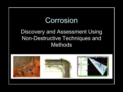
<strong>Corrosion</strong><br />
Discovery and Assessment Using<br />
Non-Destructive Techniques and<br />
Methods
Presentation Outline<br />
• Essentials for developing a corrosion<br />
monitoring program.<br />
• The need for a comprehensive corrosion<br />
monitoring program.<br />
• Tools for monitoring corrosion.<br />
• Example of a corrosion monitoring program.
Program Development<br />
• Essentials for developing a corrosion monitoring<br />
program.<br />
– Understanding of the process stream.<br />
– Identification of known and potential contaminants.<br />
– Identification of known and potential degradation<br />
mechanisms.<br />
– Assessment of metallurgy, configuration, design, and<br />
other mechanical properties that may impact<br />
corrosion severity and its location.<br />
– Assessment of actual and/ or anticipated upset<br />
conditions that may effect corrosion type, severity and<br />
location.
Why monitor corrosion?<br />
• The need for a comprehensive corrosion<br />
monitoring program:<br />
– Safety<br />
– Reliability<br />
– Extension of asset life (increased ROI)<br />
– Flexibility of fixed assets<br />
– Planning<br />
– Overall management of HSE risk
Tools: Presentation Format<br />
• Tools to be used in a corrosion monitoring<br />
program discussed as follows:<br />
– Basic Theory<br />
– Application<br />
– Discovery / Assessment Capability<br />
–Cost<br />
– Conclusion<br />
– Discussion of degradation mechanisms that<br />
tool is effective in monitoring and applications<br />
in the oil sands industry.
UT Thickness<br />
• Tool:<br />
Digital Ultrasonic Thickness Gauge<br />
• Theory<br />
–Apply voltage pulse to piezoelectric<br />
material<br />
–Induce energy (sound wave) and<br />
listen for the echo<br />
–Time of flight indicates thickness<br />
–Factors: Temperature, consistency,<br />
curvature
UT thickness<br />
• Application<br />
– Metals, plastics, composites, ceramics, and<br />
glass.<br />
– On-line or in-process measurement of<br />
extruded plastics and rolled metal is often<br />
possible, as is measurement of individual<br />
layers or coatings in multilayer fabrications.<br />
– Liquid levels and biological samples can also<br />
be measured.<br />
– Materials that are generally not suited for<br />
conventional ultrasonic gauging include wood,<br />
paper, concrete, fiberglass, and foam<br />
products
UT thickness<br />
• Discovery/ Assessment<br />
– <strong>Corrosion</strong> Type:<br />
• General/ Uniform Wall Loss<br />
– Discovery: Locate and measure general / uniform wall<br />
loss.<br />
– Assessment: Provides quantitative data for assessment<br />
of corrosion severity.<br />
• Localized Wall Loss<br />
– Discovery: Ineffective for detecting localized corrosion.<br />
When combined with a comprehensive corrosion<br />
assessment program discovery capability can be greatly<br />
increased.<br />
– Assessment: Provides quantitative assessment of<br />
identified locally corroded areas.<br />
• Mid-Wall:<br />
– Discovery - Limited capability to discover and/ or assess<br />
mid- wall conditions.<br />
– Assessment – Limited assessment capability.
UT thickness<br />
• Cost:<br />
– Very low in basic application, increases proportional<br />
to complexity.<br />
• Conclusion:<br />
– The basic building block for any comprehensive<br />
corrosion monitoring program designed to evaluate<br />
large volumes of surface areas of all types of plant<br />
equipment.<br />
– Effectiveness largely dependant on level of<br />
supporting input.<br />
– Simple technique can be employed by technicians<br />
with minimal experience and basic training (level I).
• Tool<br />
UT Flaw Detection<br />
– Ultrasonic Flaw Detector<br />
• Theory – Usually uses angle beam (shear wave)<br />
for better sensitivity<br />
• Application - detect and<br />
evaluate flaws inside<br />
component<br />
• Weld examination
UT Flaw Detection
UT Flaw Detection<br />
• Discovery/ Assessment<br />
– <strong>Corrosion</strong> Type:<br />
• General/ Uniform Wall Loss<br />
– Discovery: Locating and measure general / uniform wall<br />
loss.<br />
– Assessment: Provides quantitative data for assessment<br />
of corrosion severity.<br />
• Localized Wall Loss<br />
– Discovery: Ineffective for detecting localized corrosion.<br />
When combined with a comprehensive corrosion<br />
assessment program discovery capability can be greatly<br />
increased.<br />
– Assessment: Provides quantitative assessment of<br />
identified locally corroded areas.<br />
• Mid-Wall:<br />
– Discovery - Detection of voids, cracks, lack of weld<br />
fusion, incomplete weld filling, etc.<br />
– Assessment – Provides quantitative measurement /<br />
estimate of depth and size of flaw.
UT Flaw Detection<br />
• Cost:<br />
– Low in basic application, increases proportional to<br />
complexity.<br />
• Conclusion:<br />
– An excellent tool to assess small to moderately sized<br />
areas.<br />
– Ability to scan and query using a variety of probes.<br />
– Requires more experienced technician (level II) to<br />
adequately/ accurately evaluate/ size/ classify.
Radiographic Testing (RT)<br />
• Tool<br />
– Conventional Radiographic Testing (Industrial<br />
Radiography)<br />
• Theory<br />
– Photon source (high energy photons penetrate test<br />
material)<br />
» Isotope (Ir-192, Co-60, Cs-137, others)<br />
» X-Ray Tube<br />
– Film exposed by penetrating photons<br />
» Image represents amount of radiation emerging from<br />
opposite side of test piece<br />
» Image intensity used to measure thickness/ identify<br />
defect<br />
– Image Negative<br />
» White = more radiation<br />
» Black = less radiation
Radiographic Testing (RT)<br />
• Application<br />
– Can be used on any and all materials
Radiographic Testing (RT)<br />
• Discovery/ Assessment<br />
– <strong>Corrosion</strong> Type:<br />
• General/ Uniform Wall Loss<br />
– Discovery: Good tool for locating general/ uniform wall loss.<br />
– Assessment: Acceptable tool for assessing wall loss provided<br />
proper procedures are strictly adhered to. Provides qualitativeto-<br />
semi-quantitative data for the assessment of corrosion<br />
severity.<br />
• Localized Wall Loss<br />
– Discovery: Good tool for detecting localized corrosion.<br />
– Assessment: Acceptable tool for assessing wall loss provided<br />
proper procedures are strictly adhered to. Provides qualitativeto-<br />
semi-quantitative assessment of identified locally corroded<br />
areas.<br />
• Mid-wall<br />
– Discovery: Limited<br />
– Assessment: Limited
Radiographic Testing (RT)<br />
• Cost:<br />
– Low-to-moderate in basic application.<br />
• Conclusion:<br />
– Good tool for examining areas of potential localized corrosion.<br />
– Provides actual picture (film negative) of item/ area inspected.<br />
– Quantitative results generally require supporting methods<br />
(manual UT) for qualitative assessment of findings.<br />
– Large area must be evacuated due to radiation concerns.<br />
– Safety concerns surrounding the use of nuclear source.<br />
– Generally performed at night due to need for evacuation,<br />
increasing safety concerns and cost.<br />
– Relatively slow due to radiation control and film processing.<br />
– Size limitations.<br />
– The following quote is from an OSHA HSE study:<br />
• “Industrial radiography appears to have one of the worst<br />
safety profiles of the radiation professions, possibly because<br />
there are many operators using strong gamma sources (> 2<br />
Ci) in remote sites with little supervision when compared with<br />
workers within the nuclear industry or within hospitals.”
Computed Radiography (CR)<br />
• Tool<br />
– Computed Radiography (Digital Radiography)<br />
• Theory<br />
– Photon source (high energy photons penetrate test<br />
material)<br />
» Isotope (Ir-192, Co-60, Cs-137, others)<br />
» X-Ray Tube<br />
– Image plate exposed by penetrating photons<br />
» Image represents amount of radiation emerging from<br />
opposite side of test piece<br />
» Image intensity used to measure<br />
thickness/ identify defect<br />
– Image Negative or Positive
Computed Radiography (CR)<br />
• Application<br />
– Can be used on any and all materials
Computed Radiography (CR)<br />
• Discovery/ Assessment<br />
• General/ Uniform Wall Loss<br />
– Discovery: Good tool for locating general/ uniform wall loss.<br />
– Assessment: Acceptable tool for assessing wall loss provided<br />
proper procedures are strictly adhered to. Provides qualitativeto-<br />
semi-quantitative data for the assessment of corrosion<br />
severity.<br />
• Localized Wall Loss<br />
– Discovery: Good tool for detecting localized corrosion.<br />
– Assessment: Excellent tool for assessing wall loss provided<br />
proper procedures are strictly adhered to. Provides qualitativeto-<br />
semi-quantitative assessment of identified locally corroded<br />
areas.<br />
• Mid-wall<br />
– Discovery: Acceptable<br />
– Assessment: Good
Computed Radiography (CR)<br />
Broken wire
Computed<br />
Radiography<br />
- Wire<br />
Separation
Computed Radiography - Stack
Computed Radiography (CR)<br />
• Inspection Method: Computed Radiographic<br />
Testing<br />
– Cost: Low-to-moderate in basic application<br />
(comparable to film radiography).<br />
– Conclusion:<br />
• Requires less exposure time.<br />
• In many instances production with CR will be greater than<br />
with conventional radiography.<br />
• Image can be viewed as a whole.<br />
• Tools allow for quantitative assessment.<br />
• Electronic archiving.
Real-time Radiography (RTR)<br />
• Tool<br />
– Real-Time<br />
Radiography<br />
• Theory – Same as for<br />
conventional and digital<br />
radiography, except<br />
that image is captured<br />
“real time” and<br />
displayed on a monitor.<br />
• Application – Can be<br />
used on insulated lines<br />
and very thin wall<br />
components.<br />
C-arm<br />
pipe<br />
insulation<br />
jacket
Real-time Radiography (RTR)<br />
<strong>Corrosion</strong> Under Insulation<br />
Source:<br />
Inspection Techniques for Detecting <strong>Corrosion</strong> Under Insulation<br />
by Michael Twomey, Materials Evaluation, Vol. 55, No. 2, Feb 1997, pp. 129–132.
Real-time Radiography (RTR)<br />
- Security
Real-time Radiography (RTR)<br />
• Discovery/ Assessment<br />
• General/ Uniform Wall Loss<br />
– Discovery: Little to no ability to locate general/ uniform<br />
wall loss.<br />
– Assessment: Little to no ability to assess general/<br />
uniform wall loss.<br />
• Localized Wall Loss<br />
– Discovery: Good tool for detecting localized corrosion –<br />
external only.<br />
– Assessment: Good tool for assessing external localized<br />
corrosion. Assessment is strictly qualitative.<br />
• Mid-wall<br />
– Discovery: None<br />
– Assessment: None
Real-time Radiography (RTR)<br />
• Cost: Moderate<br />
• Conclusion:<br />
– Very good tool for inspecting piping for<br />
corrosion under insulation.<br />
– Excellent tool for locating welds under<br />
insulation.<br />
– Image can be viewed in real time.<br />
– Image can be archived electronically.
• Tool<br />
Automated UT (AUT)<br />
– Automated Ultrasonics (C-Scan)<br />
• Theory<br />
– Computer-controlled scan<br />
– Measure thickness over a surface<br />
– Use shear wave to detect smaller defects such<br />
as hydrogen-induced cracking
• Application<br />
Automated UT (AUT)<br />
– Pipes, vessels, tanks<br />
– <strong>Corrosion</strong> mapping (0-degree thickness)<br />
– Laminations, corrosion, cracking<br />
– Bond integrity<br />
– Shear-wave for plate and welds<br />
– Multi-channel for<br />
advanced HIC<br />
and other<br />
service-related<br />
damage
Automated UT (AUT)<br />
• Discovery/ Assessment<br />
• General/ Uniform Wall Loss<br />
– Discovery: Locate and measure<br />
– Assessment: Quantitative<br />
• Localized Wall Loss<br />
– Discovery: Locate and measure. For thickness<br />
measurement, need a flat reflector face. Shear<br />
wave (angle beam) more sensitive.<br />
– Assessment: Quantitative<br />
•Mid-wall<br />
– Discovery: Locate and measure<br />
– Assessment: Quantitative
•Cost:<br />
• Conclusion:<br />
Automated UT (AUT)<br />
– Complete coverage<br />
– Recorded data<br />
– Trending of thickness and crack growth<br />
– Repeatable year by year
Time of Flight Diffraction (TOFD)<br />
• Tool<br />
– Time of Flight Diffraction<br />
• Theory<br />
– Two probes in send-receive configuration<br />
– Crack tips emit a diffracted signal<br />
– Time of flight indicates depth of crack tip
TOFD /<br />
Pulse-<br />
Echo<br />
probe<br />
combos
TOFD P/E Weld Data<br />
ROOT CAP TOFD CAP ROOT
Time of Flight Diffraction (TOFD)<br />
• Application<br />
– Developed for the British Nuclear Industry<br />
– Used for sizing and trending cracks in welds<br />
– Works for OD, ID, and mid-wall cracks<br />
– Wall thickness > ½ inch<br />
– Pressure vessels<br />
and tank walls<br />
– Used in<br />
conjunction with<br />
pulse-echo to<br />
cover root &<br />
cap
Time of Flight Diffraction (TOFD)<br />
• Discovery/ Assessment<br />
• General/ Uniform Wall Loss<br />
– Discovery: Detectable using TOFD<br />
– Assessment: Accuracy comparable to<br />
conventional UT<br />
• Localized Wall Loss<br />
– Discovery: Detectable by reflection from top<br />
face<br />
– Assessment: Accuracy comparable to<br />
conventional UT<br />
•Mid-wall<br />
– Discovery: More sensitive than conventional UT<br />
– Assessment: Flaw depth and size typically<br />
within 0.5 mm in through-wall direction.
Time of Flight Diffraction (TOFD)<br />
•Cost:<br />
– Cover a typical 50-foot weld in one day<br />
(RT two days)<br />
• Conclusion:<br />
– Magnetic buggy runs probes along length of<br />
weld<br />
– Accurate and sensitive weld examination
• Tool<br />
Phased Array Ultrasonics<br />
– Phased Array Ultrasonics<br />
• Theory<br />
– Beam is steered electronically<br />
– Instantly floods weld with sound<br />
– Creates a sector scan (slice view)
Phased Array Ultrasonics<br />
• Application<br />
– Weld examination in piping and fabrication<br />
– Hydrogen-Induced Cracking<br />
– Complex geometries e.g. turbine blade roots
Phased Array on blade roots<br />
Moles and Zhang, Materials Evaluation Jan 2005
Phased Array Ultrasonics<br />
• Discovery/ Assessment<br />
• General/ Uniform Wall Loss<br />
– Discovery: Set beam at 0° for detection<br />
– Assessment: Quantitative measurement<br />
• Localized Wall Loss<br />
– Discovery: Sensitive and effective<br />
– Assessment: Evaluate flaw on Sector-scan<br />
•Mid-wall<br />
– Discovery: Sensitive and effective<br />
– Assessment: Evaluate flaw on Sector-scan
•Cost:<br />
Phased Array Ultrasonics<br />
– Productivity approximately 1.5 times that of RT.<br />
• Conclusion:<br />
– Weld examination with no need to evacuate area<br />
as with RT<br />
– Requires UT level II technicians with advanced<br />
training
Guided wave UT<br />
• Tool<br />
– Long / Guided Wave Ultrasonics<br />
• Theory<br />
– A "Guided wave" is an ultrasonic beam<br />
restricted to within a thin object such as a pipe<br />
wall<br />
– Collar is applied to pipe, sends ultrasonic beam<br />
along pipe<br />
– Can also send beam through bottom of pipe<br />
from top position<br />
– Problem areas: fittings, corrosion shadow, highdensity<br />
bonded coating, packed earth or<br />
concrete, sleeves
Guided wave UT
Guided wave UT<br />
Wavemaker Pipe Screening System by Guided Ultrasonics Ltd.
Guided wave UT- modes<br />
Longitudinal<br />
Torsional
Guided wave UT
Guided wave UT<br />
• Application<br />
– thermally insulated, coated, and buried pipe<br />
work; road-crossings<br />
– corrosion under pipe supports<br />
– detection of hidden welded joints<br />
– petrochemical process pipe work<br />
– oil and gas transmission lines<br />
– jetty lines<br />
– power station boiler tubes.
Guided wave UT<br />
• Discovery/ Assessment<br />
• General/ Uniform Wall Loss, Localized Wall Loss,<br />
and Mid-wall:<br />
– Discovery: Damage with more than 5% loss of<br />
cross-sectional area returns reflection<br />
– Assessment: Operation and interpretation<br />
highly operator dependent
•Cost:<br />
• Conclusion:<br />
Guided wave UT<br />
– No need to remove paint<br />
– Only need to remove a narrow ring of<br />
insulation for transducer application<br />
– Up to 50 meters tested to either side of a<br />
transducer ring<br />
– Typically 100 meters of pipe inspected from a<br />
test position
• Tool<br />
Acoustic Emission<br />
– Acoustic Emission Testing<br />
• Theory<br />
– Changing applied load causes crack<br />
deformation at high-stress areas - "AE events"<br />
– Sound propagates from "AE events" to sensors<br />
– Defect position obtained by triangulation<br />
– Defect type obtained by<br />
"fingerprint" on energy vs.<br />
frequency plot (next slide)<br />
Tank<br />
Crack<br />
Sensors
Acoustic Emission<br />
"fingerprinting"<br />
1. Creep<br />
2. Background<br />
noise<br />
3. Micro crack
Acoustic Emission<br />
Danger-Level evaluation
• Application<br />
Acoustic Emission<br />
– NDT of heavily mechanically stressed<br />
components or complete structures<br />
– Tank floors<br />
– Plant lines: hot reheat, main steam, cold<br />
reheat, water feed<br />
– Hangers and support performance<br />
– <strong>Monitoring</strong> line integrity
Acoustic Emission<br />
• Discovery/ Assessment<br />
• General / Uniform Wall Loss<br />
• Localized Wall Loss<br />
•Mid-wall<br />
• Early stage detection for most failure mechanisms
•Cost:<br />
Acoustic Emission<br />
– As low as 10% of current NDE Cost for some<br />
jobs<br />
• Conclusion:<br />
– In-service examination<br />
– Inspection of entire line length<br />
– No scaffolds<br />
– No insulation removal
Tubular Electromagnetic NDE<br />
• Tool<br />
– Eddy Current / Remote Field/ Magnetic Flux<br />
Leakage Testing<br />
• Theory<br />
– Magnetic field is applied to tube wall.<br />
– Defects create a response field<br />
– Response is measured for amplitude and time<br />
lag to characterize depth<br />
or volume of metal loss
Tubular Electromagnetic NDE<br />
• Application<br />
– Eddy current testing (ECT)<br />
• Heat exchangers.<br />
• Non-ferromagnetic materials such as copper,<br />
brass, cupronickel<br />
– Remote field testing (RFT)<br />
• Heat exchangers and boilers. Steel tubes and<br />
pipes<br />
• Interpretation challenging due to inconsistent<br />
magnetic properties of pipe<br />
– Magnetic Flux Leakage (MFL)<br />
• Steel tubes and pipes (generally less accurate<br />
than RFT)
Tubular Electromagnetic NDE
Tubular Electromagnetic NDE
Tubular Electromagnetic NDE<br />
• Eddy current testing: crack interrupts flow<br />
of eddy currents
Tubular Electromagnetic NDE<br />
• Discovery/ Assessment<br />
• General/ Uniform Wall Loss<br />
– Discovery: Locate and measure<br />
– Assessment: Quantitative measurement with<br />
good reference standard<br />
• Localized Wall Loss<br />
– Discovery: Eddy current very effective. Remote<br />
field and flux leakage adequate.<br />
– Assessment: Quantitative with eddy current.<br />
Volumetric with remote field and flux leakage<br />
•Mid-wall<br />
– Discovery: Only volumetric flaws. Eddy current,<br />
when flaw interrupts circumferential currents.<br />
– Assessment: Qualitative
Tubular Electromagnetic NDE<br />
•Cost:<br />
• Conclusion:<br />
– Pull speed<br />
• eddy current 2 - 5 foot per second<br />
• remote field 1 fps<br />
– Plug damaged tubes to keep component<br />
operating at peak
Internal Rotating Inspection System<br />
• Tool<br />
– Internal Rotating Inspection System (IRIS)<br />
• Theory<br />
– Rotating mirror directs ultrasonic beam into<br />
tube wall
Internal Rotating Inspection System<br />
• Application<br />
– Metallic tubes, ID 0.5 to 8 inches<br />
– Compared to electromagnetic methods, very<br />
slow but very accurate (pull speed 1 inch per<br />
second, wall thickness accuracy ± 0.005 inch)
Internal Rotating Inspection System<br />
• Discovery/ Assessment<br />
• General/ Uniform Wall Loss<br />
– Discovery: locate and measure thickness or<br />
cracks oriented right-angles to beam<br />
– Assessment: quantitative<br />
• Localized Wall Loss<br />
– Discovery: insensitive to small pits<br />
– Assessment: measures depth of reflectors<br />
•Mid-wall<br />
– Discovery: locate and measure<br />
– Assessment: quantitative
Internal Rotating Inspection System<br />
•Cost:<br />
• Conclusion:<br />
– Commonly used as a follow-up to remote field<br />
testing on selected tubes (e.g. 10 out of 1000)<br />
– For IRIS, tubes must be cleaned to bare metal<br />
– Supply of clean water required to flood tubes
Alternating Current Field<br />
Measurement<br />
• Tool<br />
– Alternating Current Field Measurement<br />
(ACFM)<br />
– Theory<br />
• Induce surface eddy currents in steel with coil<br />
• Surface-breaking cracks disrupt flow of eddy<br />
currents<br />
• Measure<br />
magnetic field<br />
to obtain depth<br />
of crack
Alternating Current Field<br />
Measurement<br />
• Application<br />
– Developed for offshore &<br />
underwater NDE<br />
– Detect surface-breaking cracks<br />
in welds in metals<br />
– Works through coating<br />
– Often replaces wet<br />
flourescent<br />
magnetic<br />
particle<br />
– Industries: civil<br />
engineering, nuclear,<br />
offshore, petrochemical,<br />
power, theme parks
Alternating Current Field<br />
Measurement
Alternating Current Field<br />
Measurement<br />
• Discovery/ Assessment<br />
• General/ Uniform Wall Loss<br />
– Discovery: Insensitive<br />
– Assessment: none<br />
• Localized Wall Loss<br />
– Discovery: Sensitive to surface-breaking cracks<br />
– Assessment: Quantitative measure of crack depth<br />
along crack face (less accurate for slanted cracks)<br />
•Mid-wall<br />
– Discovery: Insensitive<br />
– Assessment: none
•Cost:<br />
Alternating Current Field<br />
• Conclusion:<br />
Measurement<br />
– Fast compared to magnetic particle: welds<br />
done at hand-scanning speed<br />
– Sizes cracks of depth from 0.125 to 1 inch<br />
– Recorded data<br />
– Most common application: steel.<br />
– High-frequency probes available for titanium,<br />
stainless steels, etc.
Electromagnetic Acoustic<br />
Transducer<br />
• Tool<br />
– Electromagnetic Acoustic Transducer (EMAT)<br />
• Theory<br />
– Probe with magnet and coil applies an<br />
electromagnetic pulse to steel which creates an<br />
ultrasonic wave.<br />
– Return ultrasonic<br />
wave (echo)<br />
creates<br />
electromagnetic<br />
pulse, which<br />
is detected.
Electromagnetic Acoustic<br />
Transducer<br />
MAGNET<br />
Current<br />
pulse<br />
Ultrasonic<br />
wave
Electromagnetic Acoustic<br />
• Application<br />
Transducer<br />
– Thickness Measurement<br />
– Weld inspection<br />
– High temperature inspection<br />
– Automated inspection<br />
– Inspection with rough surfaces or minimal<br />
surface preparation
EMAT<br />
FST gauge®
EMAT FST gauge®
Electromagnetic Acoustic<br />
Transducer<br />
• Discovery/ Assessment<br />
• General/ Uniform Wall Loss<br />
– Discovery: Locate and measure<br />
– Assessment: Quantitative<br />
• Localized Wall Loss<br />
– Discovery: Locate and measure with shear wave<br />
– Assessment: Quantitative<br />
•Mid-wall<br />
– Discovery: Locate and measure with shear wave<br />
– Assessment: Quantitative
Electromagnetic Acoustic<br />
Transducer<br />
• Cost:<br />
• Conclusion:<br />
– Requires no couplant<br />
– High speed scanning<br />
– Non-contact; rough surfaces OK; minimal probe wear<br />
– Variety of wave modes<br />
– Thickness in ferromagnetic and bimetallic tubes<br />
– Hydrogen damage detection<br />
– Pit detection and sizing<br />
– <strong>Corrosion</strong> fatigue crack detection
<strong>Corrosion</strong> <strong>Monitoring</strong>: an Example<br />
• Example of a well developed corrosion monitoring<br />
program:<br />
– Sour Water <strong>Corrosion</strong> <strong>Monitoring</strong>:<br />
• Facts:<br />
– Relatively benign in low velocity, constant temperature stream<br />
where a protective sulfide film forms on the line to protect from<br />
corrosion.<br />
– <strong>Corrosion</strong> rates significantly increase with increasing stream<br />
velocity – at velocities > 20 ft./second corrosion rates may<br />
increase by the measure of 1 X 10 4.<br />
– Carries suspended particles that may fall out of solution when<br />
changes to stream occur.<br />
– More severe in vapor phase.<br />
– May cause secondary corrosion in the form of:<br />
» Erosion and Erosion/ <strong>Corrosion</strong><br />
» Under Deposit Pitting<br />
» <strong>Corrosion</strong> in Condensed Acids
<strong>Corrosion</strong> <strong>Monitoring</strong>: an Example<br />
• <strong>Corrosion</strong> <strong>Monitoring</strong> Program for Sour Water<br />
Equipment:<br />
– Assess process stream velocity, pressure, and<br />
temperature.<br />
– Assess mechanic design and determine areas where:<br />
• localized elevated stream velocities may occur.<br />
• Temperature changes may occur.<br />
• Process flow may be disrupted (I.e. localized turbulence or<br />
cavitation)<br />
• Pressure may change.<br />
– Assess previous inspection history or industry data on<br />
similar streams.
<strong>Corrosion</strong> <strong>Monitoring</strong>: an Example<br />
• Straight Run: Assign random points along areas<br />
with low velocity and minimal turbulence.<br />
Predominant focus in vapor phase.<br />
• Elbows: Locate elbows where sweep results in<br />
localized increases in velocity. Assign multiple<br />
points at areas with localized velocity increase<br />
(erosion and erosion-corrosion). Assign bands of<br />
points upstream of elbow (turbulence – erosion<br />
and erosion-corrosion and UDP from solids<br />
released during pressure drop).
<strong>Corrosion</strong> <strong>Monitoring</strong>: an Example<br />
• Other fittings – similar to elbows.<br />
• Stagnant areas and dead legs: Assign multiple<br />
points or grids (corrosion in condensed acids,<br />
UPD)<br />
• Areas where there are external attachments and<br />
supports. Assign multiple points, grids or scans<br />
in vicinity (corrosion in condensed acids).<br />
• When there is evidence of, or history of<br />
corrosion, closely examine potential collection<br />
areas in equipment downstream due to potential<br />
high levels of FeO 2 (UDP, CICA)
Wrap-up<br />
– No tool is a “do it all”<br />
– Tools are mutually supporting and should be used in<br />
combinations that allow the greatest return on inspection dollars<br />
invested.<br />
– The consequence of failure will generally drive the complexity of<br />
the corrosion monitoring program.<br />
– The NPRA estimates the cost of scheduled vs. unscheduled<br />
downtime to be 1:16.<br />
– Properly developed and executed corrosion monitoring<br />
programs, utilizing the appropriate tools can reduce unscheduled<br />
downtimes and reduce SHE exposure.<br />
– Properly developed and executed corrosion monitoring<br />
programs, utilizing the appropriate tools are a good investment<br />
with potential returns on investment of $16 for every $1 invested.