SHT-3005 Operation And Installation Manual - CCTV Direct
SHT-3005 Operation And Installation Manual - CCTV Direct
SHT-3005 Operation And Installation Manual - CCTV Direct

Create successful ePaper yourself
Turn your PDF publications into a flip-book with our unique Google optimized e-Paper software.
<strong>Manual</strong><br />
<strong>SHT</strong>-<strong>3005</strong> <strong>Operation</strong><br />
and <strong>Installation</strong> <strong>Manual</strong><br />
GC68-00915A ED:01
Contents<br />
This marking shown on the product or its<br />
literature, indicates that it should not be<br />
disposed with other household wastes at the<br />
end of its working life. To prevent possible<br />
harm to the environment or human health from<br />
uncontrolled waste disposal, please separate<br />
this from other types of wastes and recycle it<br />
responsibly to promote the sustainable reuse<br />
of material resources.<br />
Household users should contact either the retailer where they<br />
purchased this product, or their local government office, for details<br />
of where and how they can take this item for environmentally safe<br />
recycling.<br />
Business users should contact their supplier and check the terms<br />
and conditions of the purchase contract.<br />
This product should not be mixed with other commercial wastes for<br />
disposal.<br />
FCC NOTICE<br />
NOTE<br />
This equipment has been tested and found to comply with the limits for a Class B digital device,<br />
pursuant to part 15 of the FCC Rules. These limits are designed to provide reasonable protection<br />
against harmful interference in a residential installation.<br />
This equipment generates, uses and can radiate radio frequency energy and, if not installed and used<br />
in accordance with the instructions, may cause harmful interference to radio communications. However,<br />
there is no guarantee that interference will not occur in a particular installation. If this equipment does<br />
cause harmful interference to radio or television reception, which can be determined by turning the<br />
equipment off and on, the user is encouraged to try to correct the interference by one or more of the<br />
following measures :<br />
- Reorient or relocate the receiving antenna.<br />
- Increase the separation between the equipment and receiver.<br />
- Connect the equipment into an outlet on a circuit different from that to which the receiver is<br />
connected.<br />
- Consult the dealer or an experienced radio/TV technician for help.<br />
CAUTION<br />
Changes or modifications not expressly approved by the party responsible for compliance could void<br />
the user’s authority to operate the equipment.<br />
Preface<br />
Precautions<br />
Important Safety Instructions .................... 2<br />
General Safety Precautions....................... 4<br />
Chapter 1 : Preparation<br />
Features and Functions<br />
Product Front & Side ................................ 6<br />
Product Rear ............................................. 7<br />
Chapter 2 : Usage<br />
User Settings<br />
User Setting Mode Selection .................... 8<br />
Melody Volume Setting ............................. 9<br />
Screen Brightness Setting ........................ 9<br />
Burglar Setting .......................................... 9<br />
Automatic Image Capture Setting .............. 10<br />
(Option : <strong>SHT</strong>-<strong>3005</strong>XR)<br />
System Resetting ...................................... 10<br />
Intercom Functions<br />
Answering Visitors at the Door Camera .... 11<br />
Checking the Door Camera Exterior Area .... 12<br />
Automatic Image Capture Functions<br />
(Option : <strong>SHT</strong>-<strong>3005</strong>XR)<br />
Storing Images .......................................... 13<br />
Viewing Stored Images ............................. 13<br />
Interphone Functions (optional)<br />
Calling an Extension ................................. 14<br />
Emergency Alarm Functions<br />
In Case of an Emergency ......................... 15<br />
Chapter 3 : <strong>Installation</strong><br />
Monitor <strong>Installation</strong><br />
Installing the Monitor ................................. 16<br />
Door Camera <strong>Installation</strong><br />
Installing the Door Camera ....................... 17<br />
Wiring<br />
3 Door Cameras + 4 Monitors ................... 18<br />
2 Door Cameras + 4 Monitors + 1 Multi-Lobby Phone..... 20<br />
1 Door Camera + 1 Monitor ....................... 22<br />
Settings<br />
Cable Specifications ................................. 23<br />
Other Settings ........................................... 23<br />
Components<br />
Monitor ...................................................... 24<br />
Door Camera(Optional)................................. 24<br />
Product Specifications<br />
Specifications of the Product ..................... 25<br />
Chapter 4 : Other Information<br />
Troubleshooting<br />
Check This First! .......................................... 27<br />
Product Warranty<br />
Product Warranty ......................................... 28<br />
Contents<br />
1
Precautions<br />
* Please review the content below to ensure safe and precise product usage.<br />
C A U T I O N<br />
RISK OF ELECTRIC SHOCK<br />
DO NOT OPEN<br />
<br />
<br />
<br />
<br />
<br />
<br />
Preface<br />
CAUTION<br />
To reduce the risk of electric shock, do not remove the top cover (or the rear section).<br />
No user serviceable parts inside, refer servicing to qualified personnel.<br />
This symbol, wherever it appears, alerts you to the presence of uninsulated dangerous<br />
voltage inside the enclosure-voltage that may be sufficient to constitute a risk of shock.<br />
<br />
<br />
<br />
This symbol, wherever it appears, alerts you to the important operating and maintenance<br />
instructions in the accompanying literature. Please read the manual.<br />
I Important Safety Instructions<br />
<br />
<br />
<br />
<br />
<br />
<br />
<br />
<br />
<br />
<br />
<br />
<br />
<br />
<br />
<br />
<br />
<br />
<br />
<br />
<br />
<br />
<br />
<br />
<br />
<br />
<br />
<br />
<br />
<br />
<br />
2<br />
3
Precautions<br />
* Please review the content below to ensure safe and precise product usage.<br />
I Safety Precautions<br />
WARNING<br />
Neglecting to follow these directions<br />
can result in death or serious injury.<br />
CAUTION<br />
Neglecting to follow these directions can<br />
result in injury or material loss.<br />
Do not use pins or any sharp, pointy<br />
objects to press buttons, or insert them<br />
into holes.<br />
This may cause product electrical shock and/or<br />
fire.<br />
Do not clean using a wet cloths or a volatile<br />
substances (e.g. alcohol, benzene, thinner).<br />
This may cause product electrical shock and/or fire.<br />
Preface<br />
WARNING<br />
Do not disassemble, install, or repair this<br />
product on your own initiative.<br />
Contact the service center regarding any repair<br />
needs.<br />
Unauthorized handling<br />
may cause product<br />
malfunction, electric<br />
shock, and/or fire.<br />
“Disconnecting the device from<br />
mains-The mains plug is the means of disconnecting<br />
the device. The plug must remain readily operable.”<br />
Do not subject the product to any heavy<br />
shock such as striking with a hard object<br />
(e.g. hammer, etc.).<br />
This may cause product<br />
malfunction, electrical<br />
shock, and/or fire.<br />
If the product emits any peculiar noise, odor,<br />
and/or smoke, immediately turn off the circuit<br />
breaker connected to the electric heater<br />
switch (ONT product connection)<br />
in the power cabinet panel,<br />
and then contact the<br />
service center.<br />
Be aware of the risk of<br />
electrical shock and/or fire.<br />
Do not place the product near a heat<br />
source (e.g. heater) or a source of<br />
moisture (e.g. aquarium, humidifier).<br />
This may cause product<br />
malfunction and/or fire.<br />
Do not allow water or other liquid to enter<br />
the product.<br />
This may cause electrical<br />
shock and/or fire.<br />
“The device must not be<br />
exposed to dripping or<br />
splashing and no object,<br />
filled with liquids, such as a<br />
vase, shall be placed on<br />
the device.”<br />
Do not allow water to enter the camera<br />
when cleaning.<br />
This may result in electrical<br />
shock and/or fire.<br />
“WARNING-To Reduce The<br />
Risk Of Fire Or Electric Shock,<br />
Do Not Expose This Apparatus<br />
To Rain Or Moisture.”<br />
After receiving service, ask the service representative to perform a safety inspection.<br />
CAUTION<br />
Do not hang on or pull on the installed<br />
product.<br />
Take special care to<br />
prevent such mishanding<br />
of the product<br />
by small children as<br />
injury may occur.<br />
If you are leaving the product in a dwelling when you move, make<br />
sure to pass the user manual on to the new home owner/tenant.<br />
This is important to prevent any misuse of the product by the new home<br />
owner/tenant.<br />
Be careful when standing up after sitting<br />
under the installed product.<br />
A head injury may<br />
occur from any<br />
impact with the<br />
installed product.<br />
4<br />
5
Features and Functions<br />
Chapter 1<br />
I Product Front & Side<br />
Handset<br />
The handset is used to communicate with a visitor who is standing in<br />
front of the door camera, or to make calls to an extension. When not in<br />
use for communication, lifting the handset allows the user to view the<br />
exterior area of the unit entrance.<br />
Monitor<br />
Visitors are shown on screen.<br />
Power Indicator Lamp<br />
When power is normal, the indicator<br />
lamp is illuminated in blue.<br />
I Product Rear<br />
JP4/5/6 : Sub 1/2/3 Connector Terminals<br />
Connects the extension / sub-monitors in sequence.<br />
S1 : Various Settings SW<br />
Used for setting the door camera, main<br />
monitor, extension / sub-monitors, etc.<br />
JP400 : Multi-lobby phone Jumper<br />
Used to set the multi-lobby phone connection.<br />
JP1/2/3 : CAM1/2/3 Connector Terminals<br />
Connects the door cameras in sequence.<br />
Preparation<br />
Interphone Button/Lamp<br />
This is used to communicate with a sub unit.<br />
POWER Switch<br />
Use to turn power on and off.<br />
Door Button/Lamp<br />
This is used to answer calls from a visitor who<br />
is standing in front of the door camera .<br />
Open Button/Lamp<br />
This is used to open the entrance door during<br />
a call.<br />
Mode Button<br />
This is used to make changes to<br />
various settings. (eg. melody<br />
volume, screen brightness)<br />
+/- Button<br />
This is used to adjust<br />
communication volume, melody<br />
volume and screen brightness.<br />
Speaker<br />
Sounds melody, alarms, etc.<br />
JP7 : EXT Connector Terminal<br />
Connects the door lock and other external peripherals.<br />
JP13/14 : Main/Sub Selection Jumper<br />
Used to set the product as a main monitor or as an extension / submonitor.<br />
Note<br />
Communication Volume Adjustment<br />
Press the + or - button to adjust communication volume during calls.<br />
Melody Volume Adjustment<br />
After pressing the Mode button and selecting a Melody Setting, press the + or - button to adjust.<br />
Screen Brightness Adjustment<br />
After pressing the Mode button and selecting a Brightness Setting, press the + or - button to<br />
adjust.<br />
6<br />
7
User Setting Functions<br />
Set some product functions in advance according to the usage environment.<br />
Chapter 2<br />
I User Setting Mode Selection<br />
1<br />
When<br />
not in use, press the MODE<br />
button to view the User Settings<br />
menu on the screen.<br />
2<br />
Press the + or - buttons to scroll<br />
and select the desired setting<br />
mode.<br />
I Melody Volume Setting<br />
1<br />
After<br />
entering the Melody Setting<br />
Mode, press the + or - buttons to<br />
adjust the melody volume.<br />
I Screen Brightness Setting<br />
1<br />
When<br />
entering the Screen<br />
Brightness Setting Mode, the view<br />
seen from door camera will<br />
appear. Press the + or - buttons<br />
to adjust the screen brightness.<br />
Usage<br />
Setting Mode<br />
1. Melody Set<br />
2. Burglar Set<br />
3. Bright Set<br />
4. Capture Set<br />
5. Reset<br />
Ver. 1.X<br />
Setting Mode<br />
1. Melody Set<br />
2. Burglar Set<br />
3. Bright Set<br />
4. Capture Set<br />
5. Reset<br />
Ver. 1.X<br />
Melody Set<br />
Mel Volume : 2<br />
Press the MODE button to return the screen to the main<br />
menu.<br />
After the melody settings have been made, the melody<br />
volume of door camera calls and calls to<br />
extensions(interphone) will be adjusted equally.<br />
Press the MODE button to return to the main menu.<br />
3<br />
Press<br />
the MODE button to enter<br />
the selected setting mode.<br />
Note<br />
User Setting Mode<br />
I Burglar Setting<br />
Melody Set<br />
Mel Volume : 2<br />
Setting Mode<br />
1. Melody Set<br />
2. Burglar Set<br />
3. Bright Set<br />
4. Capture Set<br />
5. Reset<br />
Ver. 1.X<br />
Set Melody Volume<br />
Set Burglar Mode<br />
Set Screen Brightness<br />
Set Image Capture Mode<br />
Reset System<br />
1<br />
In<br />
the Burglar Setting Mode,<br />
pressing the + button will activate<br />
the burglar alarm, and the OPEN<br />
lamp will turn red.<br />
2<br />
Pressing<br />
the - button will deactivate<br />
the burglar alarm function, and the<br />
OPEN lamp will turn blue.<br />
To exit the User Setting Mode, press and hold the<br />
MODE button for 2~3 seconds.<br />
The Automatic Image Capture setting is available only<br />
on product model <strong>3005</strong>XR.<br />
Burglar Set<br />
Burglar On<br />
Burglar Set<br />
Burglar Off<br />
CAUTION:<br />
This function can only be activated when the door is fully<br />
closed and the magnetic door entry contact sensor is<br />
installed.<br />
Press the MODE button to return to the<br />
main menu.<br />
8<br />
9
User Setting Functions<br />
Set some product functions in advance according to the usage environment.<br />
Intercom Functions<br />
Intercom functions include the ability to speak with visitors and to open the entrance door.<br />
Chapter 2<br />
I Automatic Image Capture Setting<br />
1<br />
In<br />
the Automatic Image Capture<br />
Setting Mode, pressing the +<br />
button will activate the automatic<br />
image capture function.<br />
(Option : <strong>SHT</strong>-<strong>3005</strong>XR)<br />
2<br />
Pressing<br />
the - button will deactivate<br />
the automatic image capture<br />
function.<br />
I Answering Visitors at the Door Camera<br />
1<br />
The<br />
monitor sounds a melodic chime,<br />
and the visitor appears on the screen.<br />
To speak to the visitor, lift the handset.<br />
Usage<br />
Capture Set<br />
Capture Set<br />
Capture Mode :<br />
Capture Mode :<br />
Auto<br />
Normal<br />
During automatic image capture, if a visitors presses the<br />
call button that activates the door camera, the visitor’s<br />
image will automatically be saved in black and white.<br />
Press the MODE button to return to the main menu.<br />
If the handset is not lifted within a fixed period of time, the<br />
screen will turn off.<br />
The maximum time per call is one minute.<br />
I System Resetting<br />
2<br />
During<br />
a call, pressing the OPEN<br />
button will open the entrance door.<br />
3<br />
To<br />
end a call, place the handset in its<br />
normal position.<br />
1<br />
In<br />
the Reset System Mode,<br />
pressing the + button will reset all<br />
settings to their original factory<br />
settings.<br />
Reset<br />
Push Plus Key<br />
Note<br />
Settings after system reset<br />
- Melody : 2<br />
- Burglar : Off<br />
- Bright : 2<br />
Note<br />
1. An electric door strike and digital door lock are supplied separately as an option.<br />
2. To adjust the volume during a call, use the + or - buttons.<br />
10<br />
11
Intercom Functions<br />
Functions include viewing the exterior area of the unit entrance.<br />
For 1 Door Camera<br />
Lift the handset, and the front view of the<br />
door camera will appear on the screen.<br />
1<br />
Pressing<br />
Automatic Image Capture Functions<br />
(Option : <strong>SHT</strong>-<strong>3005</strong>XR)<br />
Functions include the storing and viewing of visitor images.<br />
I Checking the Door Camera Exterior Area I Storing Images I Viewing Stored Images<br />
the MODE button during<br />
a call will capture and store the<br />
image of the visitor.<br />
1<br />
When<br />
not in use, press and hold<br />
the DOOR button for two seconds.<br />
Chapter 2<br />
Usage<br />
The front view of the door camera area automatically<br />
turns off after 50 ~ 60 seconds.<br />
The image of the visitor will be stored.<br />
(requires 8 ~ 12 seconds)<br />
After setting the automatic image capture function, the<br />
DOOR lamp will blink when a visitor image has been stored.<br />
The image of the most recently saved visitor image will<br />
appear.<br />
For 2 or More Door Cameras(optional)<br />
If you have 2 or more door cameras installed, it will function as follows ;<br />
Lift the handset to see the front view of door camera 1, and then press the DOOR button to<br />
see subsequent door camera views in sequential order.<br />
2<br />
Scroll<br />
using the + or - buttons to<br />
see the stored visitor images<br />
2<br />
When<br />
viewing a stored visitor<br />
image, pressing the MODE button<br />
will delete that image.<br />
If no button is pressed for approximately 10seconds,<br />
the viewing mode will be cancelled and the unit will<br />
return to standby mode.<br />
If no button is pressed for approximately 10 seconds,<br />
viewing mode will be cancelled and the unit will<br />
return to standby mode.<br />
12<br />
13
1<br />
Lift<br />
Interphone Functions (Optional)<br />
Functions apply to calls between units when 2 or more monitors have been installed.<br />
I Calling an Extension<br />
the handset and press the<br />
INTERPHONE button.<br />
2<br />
The<br />
melody will sound on the other<br />
monitor and the call is connected<br />
when the handset is lifted.<br />
1<br />
When<br />
Emergency Alarm Functions<br />
I In Case of an Emergency<br />
the external emergency<br />
sensor is activated, an alarm will<br />
sound and the word “Emergency”<br />
will flash on the monitor screen.<br />
2<br />
To deactivate the alarm, press the<br />
MODE button.<br />
The alarm will turn off.<br />
Chapter 2<br />
Usage<br />
Emergency<br />
Emergency<br />
Note<br />
1. This function is available when 2 or more monitors are installed. It is not possible to call a specific<br />
extension / monitor or to call several parties simultaneously.<br />
2. If the receiving party does not answer a call within 30 seconds, the call is automatically terminated.<br />
3. Interphone calls are automatically terminated after approximately 3 minutes.<br />
In the case of an emergency, one or more of the<br />
follow alarm messages will be displayed.<br />
- For a General Emergency : Emergency<br />
- For a Fire : Fire<br />
- For the Intrusion of a Burglar : Burglar<br />
3<br />
Resetting<br />
the external emergency<br />
sensor will return the unit to its<br />
normal standby mode.<br />
Note<br />
In Case of an Emergency<br />
Pressing the MODE button will deactivate the alarm<br />
word “Emergency” will flash. Check the external switch<br />
where the emergency was activated, and turn it off to<br />
return the screen to its normal standby mode.<br />
In Case of a Burglar<br />
Pressing the MODE button will deactivate the alarm, and<br />
the screen will flash. Closing the door will return the<br />
screen to its normal standby mode.<br />
14<br />
15
Monitor <strong>Installation</strong><br />
I Installing the Monitor<br />
Product <strong>Installation</strong> Diagram - Monitor <strong>Installation</strong> Method and Height<br />
Door Camera <strong>Installation</strong><br />
I Installing the Door Camera<br />
Door Camera <strong>Installation</strong> Diagram - Door Camera <strong>Installation</strong> Method and Height<br />
<strong>SHT</strong>-CN510 (Optional : only for <strong>SHT</strong>-<strong>3005</strong>XA model)<br />
Chapter 3<br />
<strong>Installation</strong><br />
57.1inch<br />
5.4inch<br />
57.1inch<br />
27.6inch<br />
3.6inch<br />
05.inch<br />
27.6inch<br />
<strong>SHT</strong>-CP610 (Optional : only for <strong>SHT</strong>-<strong>3005</strong>XB model)<br />
57.1inch<br />
WARNING<br />
Beware of electrical shock or fire when connecting to AC power.<br />
<strong>Installation</strong> Method<br />
1. Select an appropriate site for product installation.<br />
(Set product height so that the center of the monitor is at least 145cm from the floor.)<br />
2. Affix the wall mount bracket at the selected site using the 4 screws.<br />
3. Connect the door camera wire and the sub-monitor (optional) wires to the monitor terminal.<br />
4. After mounting the monitor on the bracket, affix the screw at the base of the unit.<br />
5. Connect the AC power cord.<br />
6. Turn on the power switch at the bottom of the unit and confirm power supply to the product.<br />
<strong>Installation</strong> Method<br />
1. Select an appropriate site for product installation.<br />
(Set product height so that the center of the door camera is at least 145cm from the floor.)<br />
2. Affix the wall mount bracket at the selected site using the two screws.<br />
3. Connect the monitor connection wire to the door camera terminal.<br />
4. Confirm that the function of calling to the monitor is operable.<br />
<strong>Installation</strong> Precautions<br />
1. Avoid installation in areas that are exposed to direct sunlight, rain, chemicals, and/or high voltage<br />
electrical cables.<br />
2. Avoid installation in areas of excessive heat or cold.<br />
27.6inch<br />
16<br />
17
Wiring<br />
I 3 Door Cameras + 4 Monitors (1 Main + 3 Sub)<br />
Sub 3<br />
C<br />
<br />
<br />
A<br />
<br />
<br />
Chapter 3<br />
<strong>Installation</strong><br />
Door Camera 3<br />
Sub 2<br />
Door Camera 2<br />
B<br />
Sub 1<br />
<br />
<br />
Main<br />
Door Camera 1<br />
0.65mm<br />
22AWG<br />
1.0mm<br />
18AWG<br />
A<br />
30m<br />
100’<br />
60m<br />
200’<br />
Door Lock 2<br />
Door Lock 1<br />
B<br />
C<br />
30m<br />
15m<br />
100’<br />
50’<br />
60m<br />
30m<br />
200’<br />
100’<br />
Note<br />
The CAM3 does not support door release function.<br />
Do not connect a door camera to the CAM3 for the door release during a call.<br />
18<br />
19
Wiring<br />
I 2 Door Cameras + 4 Monitors (1 Main + 3 Sub) + 1 Multi-Lobby Phone<br />
Sub 3<br />
<br />
<br />
<br />
<br />
Chapter 3<br />
<strong>Installation</strong><br />
Sub 2<br />
Door Camera 2<br />
Multi-Lobby<br />
Phone<br />
Sub 1<br />
<br />
<br />
Main<br />
Door Camera 1<br />
An electric door strike<br />
connected to Multi-Lobby<br />
Phone requires it’s own<br />
power source.<br />
Door Lock 1<br />
Note<br />
1. The CAM3 dose not support door release function. Do not connect a camera to the CAM3 for the<br />
door release during a call.<br />
2. Connect the Multi-Lobby Phone to the CAM2 only. The door strike contacts on the Multi-Lobby<br />
Phone may not work if connecting the Multi-Lobby Phone to the CAM1 or CAM3.<br />
3. The rating of an electric door strike contacts on the Multi-Lobby Phone supports Max. at 250V AC,<br />
2A or 30V DC, 5A. (Any electric door strike rating below 250V AC, 2A or 30V DC, 5A can be used<br />
with Multi-Lobby Phone.)<br />
20<br />
21
Wiring<br />
Settings<br />
Chapter 3<br />
I 1 Door Camera + 1 Monitor(Main)<br />
<br />
<br />
<br />
<br />
I Cable Specifications<br />
Main and Sub Connection [4pin]<br />
1 [RED] VOICE<br />
2 [GREEN] COMM<br />
3 [WHITE] VIDEO<br />
4 [BLACK] GND<br />
External Expansion Connection [12pin]<br />
1/2 [RED/WHITE] Door Lock 1<br />
3/4 [ORANGE/WHITE] Door Lock 2<br />
5/6 [YELLOW/WHITE] Fire Sensor<br />
7/8 [GREEN/WHITE] Magnetic Sensor<br />
9/10 [BLUE/WHITE] Emergency Switch<br />
<strong>Installation</strong><br />
Monitor and Door Phone Connection [4pin]<br />
11/12 [VIOLET/WHITE] External Lamp<br />
1 [RED] + 12V<br />
2 [GREEN] VOICE<br />
CAUTION<br />
3 [WHITE] VIDEO<br />
4 [BLACK] GND<br />
Do not connect to AC power.<br />
It may result in electrical shock and/or fire.<br />
<br />
<br />
Door Camera 1<br />
I Other Settings<br />
Sub/Main Setting [JP13/14]<br />
Other Settings SW [S1]<br />
Main<br />
When using as main:<br />
Insert jumper<br />
When using as sub:<br />
Remove jumper<br />
Main Monitor / 1 Door Camera Setting<br />
When Using as Main : ON<br />
When Using only 1 Door Camera: OFF<br />
Door Lock 1<br />
JP13<br />
JP14<br />
JP13<br />
JP14<br />
Additional Door Camera Setting (only for Main)<br />
[pin 1/2/3 of S1]<br />
When using 1 Camera When using 2 Cameras When using 3 Cameras<br />
Multi-Lobby Phone Setting [JP400]<br />
Without the multi-lobby<br />
phone : Insert jumper<br />
With the multi-lobby<br />
phone : Remove jumper<br />
Sub Monitor Setting [pin 1/2/3/5/8 of S1]<br />
When using as Sub1 When using as Sub2 When using as Sub3<br />
JP400<br />
JP400<br />
CAUTION<br />
Make sure to turn power off before changing the<br />
S/W settings.<br />
22<br />
23
I Monitor<br />
Components<br />
The following is a list of <strong>SHT</strong>-<strong>3005</strong> components. Please start by confirming that all components listed below<br />
have been included.<br />
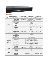
Product Specifications<br />
I Specifications of the Product<br />
Household Unit<br />
Device<br />
Category<br />
Specifications<br />
Input Power<br />
AC 100V ~ 220V 20%, 50Hz/60Hz<br />
SMPS<br />
Maximum Power Consumption<br />
20W<br />
DC Output Voltage / Current<br />
12V / 1.8A<br />
Weight<br />
400g / 0.9lb<br />
Chapter 3<br />
<strong>Installation</strong><br />
Communication Mode<br />
Handset Communication<br />
Monitor Screen Size<br />
5-Inch LCD<br />
LCD Resolution (dot)<br />
320(H) x 240(V)<br />
(Two Product Fixing Screw Added)<br />
LCD Back-light<br />
CCFL Back-light Type<br />
LCD Back-light Life Cycle<br />
10,000 Hours 25<br />
LCD Screen Visible Angles<br />
Horizontal : 45, Vertical : +30/-10<br />
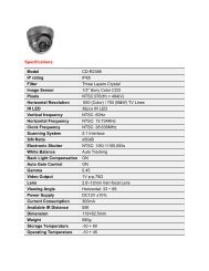
I Door Camera (Optional)<br />
<strong>SHT</strong>-<strong>3005</strong><br />
Video Signal Scanning<br />
Video Signal Wire Connection<br />
US : NTSC (Composite), EN : PAL (Composite)<br />
Two-Wire Connection<br />
<strong>SHT</strong>-CN510 (Optional : only for <strong>SHT</strong>-<strong>3005</strong>XA model)<br />
Camera Transmission<br />
Diameter : 0.65mm<br />
Distance<br />
Optimal Distance : 30m or less<br />
Chime Melody<br />
Ding~Dong<br />
Main Unit Electricity Consumption<br />
1.5 A<br />
Weight (Main Unit)<br />
1.2 Kg / 2.7 lb<br />
Dimensions<br />
275mm (W) x 125mm(H) x 40mm (D)<br />
10.8inch(W) x 4.9inch(H) x 1.6inch(D)<br />
<strong>SHT</strong>-CP610 (Optional : only for <strong>SHT</strong>-<strong>3005</strong>XB model)<br />
24<br />
25
Product Specifications<br />
Troubleshooting<br />
Chapter 4<br />
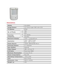
Door Camera<br />
<strong>SHT</strong>-CN510 (Optional : only for <strong>SHT</strong>-<strong>3005</strong>XA model)<br />
Device<br />
Door<br />
Camera<br />
Category<br />
Input Power<br />
Video Signal Scanning Mode<br />
Weight (Main Unit)<br />
Dimensions<br />
Specifications<br />
DC 12V (Receive power from monitor)<br />
US : NTSC (Composite), EN : PAL (Composite)<br />
150 g / 0.3 lb<br />
92mm(W) x 136mm(H) x 12mm(D)<br />
3.6inch(W) x 5.4inch(H) x 0.5inch(D)<br />
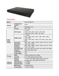
<strong>SHT</strong>-CP610 (Optional : only for <strong>SHT</strong>-<strong>3005</strong>XB model)<br />
Device<br />
Category<br />
Specifications<br />
I Check This First!<br />
The power does not turn on.<br />
Ensure that the power is connected.<br />
The screen is too dark.<br />
Check the exterior lighting conditions in the area of the camera.<br />
Clean the exterior surface of the door camera.<br />
Adjust the screen brightness, using the function settings. (refer to page 9)<br />
Screen brightness can be set to one of 4 levels. The factory default setting is 2.<br />
Other Information<br />
Input Power<br />
DC 12V (Receive power from monitor)<br />
Door<br />
Camera<br />
Video Signal Scanning Mode<br />
Weight (Main Unit)<br />
Dimensions<br />
US : NTSC (Composite), EN : PAL (Composite)<br />
390 g / 0.9 lb<br />
96mm(W) x 129mm(H) x 24mm(D)<br />
3.8inch(W) x 5.1inch(H) x 0.9inch(D)<br />
There is too much noise during calls.<br />
Check to see if the door phone line has been short-circuited with the ground.<br />
Calls are not audible.<br />
Check the volume setting.<br />
Check the wire connection between the monitor and the camera.<br />
26<br />
27
Product Warranty<br />
I Product Warranty<br />
Seoul Commtech products are supplied with a one (1) year warranty based on the<br />
date of purchase, during which time any defective product will be repaired or<br />
replaced with a new or factory rebuilt replacement at no charge.<br />
Warranty Conditions<br />
1. This warranty applies to the original purchaser only.<br />
2. The warranty is void if any unauthorized repair or modifications are<br />
performed to the unit, or in any case of accident, misuse, damage caused by<br />
improper installation or altered serial numbers.<br />
3. If warranty service is required, the customer must send the product to the<br />
customer service center or to an authorized dealer. In all cases, the product must<br />
be accompanied by the following items: customer name, address, telephone<br />
number, product serial numbers, and a copy of the purchase receipt that shows<br />
the purchase date and location.<br />
The product model number is included on the package and on the front of the<br />
manual. The serial number is located on the product unit. Please record the<br />
product model number and serial number in the spaces provided below. Refer to<br />
these numbers for warranty service.<br />
Model No.<br />
Serial No.<br />
28