A.C. Electrical Testing and Troubleshooting Guide - Westerbeke
A.C. Electrical Testing and Troubleshooting Guide - Westerbeke
A.C. Electrical Testing and Troubleshooting Guide - Westerbeke

Create successful ePaper yourself
Turn your PDF publications into a flip-book with our unique Google optimized e-Paper software.
A C ELECTRICAL TESTING<br />
AND TROUBLESHOOTING GUIDE<br />
Be GEN<br />
TORS<br />
~ WESTERBEKE<br />
WESTERBEKE CORPORATION· MYLES STANDISH INDUSTRIAL PARK<br />
150 JOHN HANCOCK ROAD, TAUNTON, MA 02780-7319 U.S.A.<br />
TEL: (508)823-7677· FAX: (508)884-9688· WEBSITE: www.WESTERBEKE.COM<br />
- WESTERBEKE #65103 .<br />
.tWA MI!m1nr National MariM MWlujactu.rm As,rocialioll<br />
MARCH 2000 2ND EDITION
TABLE OF CONTENTS<br />
BC Generator <strong>Electrical</strong> <strong>Testing</strong> ............................ 2 Battery Charging Circuit/Bridge Rectifier ......... 10<br />
Generator <strong>Troubleshooting</strong> Chart...: ................. 2 <strong>Testing</strong> the Bridge Rectifier .......................... .1 0<br />
Internal Wiring Schematic .................................. 3 Integral Controller/Ballast Resistor .................. 11<br />
AC Terminal Board, .............................................. 3 Integral Controller (LC.) ............................... .11<br />
Low Voltage-Rotating Field Windings Tests .......4 Ballast Resistor ..........................,................... 11<br />
<strong>Testing</strong> the Diodes ............................................4<br />
Measuring Resistance .................................... 11<br />
<strong>Testing</strong> the Rotor Field Windings ..................... 5 Integral Controller/No-Load Voltage Adj . ............ 12<br />
Residual Voltage Exciter Circuit Tests ................. 6 <strong>Testing</strong> the Integral Controller ...................... 12<br />
Fuse Protection .............................................. 12<br />
<strong>Testing</strong> the Exciter Windings ........................... 6<br />
Single/Dual Capacitor No-Load<br />
Exciter Circuit Capacitor(s) Tests ........................ 7<br />
Voltage Adjustment ....................................... 12<br />
Measuring Resistance ....................................... 7<br />
Checking Continuity ......................................... 7<br />
No-Load Voltage Adjustment Dual Exciter ........ 13<br />
<strong>Testing</strong> the Capacitor(s) .................................... 7 Dual Exciter Circuit Model ........................... 13<br />
Exciting the Generator ...................................... 8 BC Generator Parts Identification ....................... 14<br />
No Voltage Main Stator Windings Tests ............. 8<br />
<strong>Testing</strong> Residual Voltage .................................. 8<br />
Checking Resistance ......................................... 8<br />
T . C ..<br />
estmg ontmlilty ............................................. 9<br />
-.Y' WESTERBEKE<br />
Engines & Generators<br />
1
OESCRIPTION<br />
The Be generator is a brushless, self-excited generator which<br />
requires only the driving force of the engine to produce an<br />
AC output. The stator houses two sets of windings; the main<br />
stator windings <strong>and</strong> the exciter windings. When the generator<br />
is started, residual magnetism in the four rotating poles<br />
induces a voltage in the stator which then generates an even<br />
larger voltage in the exciter windings. This mutual build up<br />
of voltage in the four rotating poles <strong>and</strong> in the exciter windings<br />
quickly reaches the saturation point of the capacitor(s)<br />
<strong>and</strong> a regulated energy field is then maintained in the stator.<br />
At the same time, this regulated field produces a steady volt~<br />
age in the stator windings which can then be drawn off the<br />
generator's AC tenrunals to operate AC equipment. The<br />
generator is a single-phase, reconnectable 120 volt AC<br />
two-wire or 115 voltAC two-wire or 230 voltAC two-wire,<br />
at 50 hertz.<br />
BC GENERATOR ELECTRICAL TESTING<br />
The generator's data plate gives the voltage, current <strong>and</strong><br />
frequency rating of the generator. An AC wiring decal is<br />
affixed to the inside of the louvered cover at the generator<br />
end. A diagram of the various AC voltage connections is<br />
provided on the decal. An Integral Controller (IC) is mounted<br />
inside the generator <strong>and</strong> supplies a continuous DC charge to<br />
the generators starting battery when the generator is running.<br />
INTROOUCTION TO TROUBLESHOOTING<br />
The following test procedures can be used to troubleshoot<br />
WESTERBEKE'S 4 POLE SINGLE AND DUAL CAPACI<br />
TOR BRUSHLESS GENERATORS. Due to the simplicity<br />
of the generator, troubleshooting is relatively easy.<br />
Field testing <strong>and</strong> repairing can be accomplished with basic<br />
tools <strong>and</strong> repair parts which should include the following:<br />
A quality multimeter [muititesterj capable of reading<br />
less than one ohm <strong>and</strong> with a specific diode testing<br />
function.<br />
Basic electrical tools including cutters, soldering iron,<br />
wire strapperlcrimper, terminals connectors, etc.<br />
Repair parts such as diodes, fuses, bridge rectifier, etc.<br />
PRELIMINARY CHECKING<br />
Before electrical testing check for proper engine<br />
speed/hertz adjustment. Low engine speed will cause low<br />
AC voltage output, high engine speed~high AC output.<br />
Refer to WESTERBEKE'S operators manual or service<br />
manual for engine speed/hertz adjustment or for other<br />
possible engine related problems.<br />
Before testing, get a clear explanation of the problem that<br />
exists, be certain it relates to generator components.<br />
A WARNING: AC <strong>and</strong> DC circuits often share the same<br />
distributor panel. Be certain to unplug AC power cords<br />
<strong>and</strong> shutdown DC/AC Inverters. Simply switching off<br />
circuit breakers will not do the Job since it will stili<br />
leave hot wires on the supply side of the panel.<br />
I "'fIIV'IWESTERBEKE<br />
I Engines & Generators<br />
2<br />
GENERATOR TROUBLESHOOTING CHART<br />
A, B, C, & 0 refer to the components of the INTERNAL WIRING<br />
DIAGRAM <strong>and</strong> their test procedures in the following pages.<br />
NOTE: This fault finding chan is compiled assuming the engine<br />
is operating at the correct speed/henz.<br />
FAULT CAUSE TEST/CORRECTION<br />
No AG Output Shorted stator B<br />
Open stator<br />
B<br />
Shorted diodes [two] A<br />
Residual Voltage Faulty capacitor C<br />
4-6 VAG (Hot N) Open exciter B<br />
at no-load<br />
Shorted exciter B<br />
Engine speed [hertz]<br />
is too low<br />
Adjust'<br />
<strong>Electrical</strong> connections Inspect wiring<br />
are faulty<br />
connections<br />
High AC Output Incorrect voltage tap<br />
at No-Load on capacitor C<br />
Incorrect capacitor C<br />
Incorrect hertz tap<br />
;on capacitor<br />
C<br />
Engine speed [hertz]<br />
is too hiqh<br />
. Adjust'<br />
Low AC Output Faulty rotor winding A<br />
60-106V Faulty diode A<br />
Faulty capacitor<br />
!:I<br />
Voltage Drop Faulty diode A<br />
Under Load<br />
Faulty capacitor C<br />
(or at No-Load)<br />
Engine speed [hertz]<br />
is too low Adjust'<br />
No Battery Charge Faulty bridge rectifier D<br />
Low Battery Charge<br />
Faulty integral controller D<br />
Blown fuse<br />
B<br />
Faulty winding B<br />
High Voltage Engine speed [hertz]<br />
Output when Load . is too high<br />
Adjust'<br />
is applied<br />
Unstable Voltage <strong>Electrical</strong> connections Inspect wiring<br />
are faulty, loose<br />
connections<br />
Noisy Operation Faulty support bearing I nspect rear<br />
bearing"<br />
Generator rotor<br />
connection to engine Check rotor<br />
is loose<br />
security"<br />
• Refer to the GENERATORS OPERATOR MANUAL<br />
** Refer to the GENERATORS SERVICE MANUAL
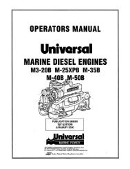
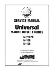
Be GENERATORS PARTS<br />
INTEGRAL CONTROLLER<br />
GROUND TERMINAl<br />
EARLY BC MODELS<br />
BC GENERATORS<br />
ELECTRICAL COMPONENTS<br />
[DUAL CAPACITOR SHOWN]<br />
GENERATOR<br />
CASE<br />
AC TERMINAL<br />
BOARD<br />
\<br />
/ •...)<br />
0/<br />
BALLAST RESISTER<br />
[EARLY MODElSj<br />
CAPACITOR<br />
CURRENT MODEL<br />
B C GENERATORS<br />
ELECTRICAL COMPONENTS<br />
[SINGLE CAPACITOR SHOWN]<br />
. ,~NTEGRAL CONTROLLER<br />
(~ilif"',<br />
,<br />
j<br />
30 AMP FUSE<br />
CURRENT MODEL<br />
B C GENERATORS<br />
INTEGRAL CONTROLLER<br />
// ..... _;y._- ......<br />
'
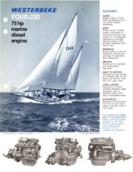
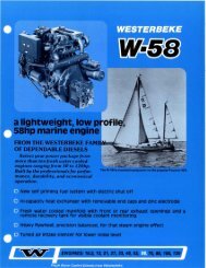
INTERNAL WIRING SCHEMATIC<br />
DC BATTERY CHARGING CIRCUIT<br />
FUSE - INTEGRAL CONTROLLER ______________________ _<br />
D<br />
A - ROTOR WINDINGS<br />
.<br />
8 - STATOR WINDINGS<br />
I ,<br />
C • CAPACITOR WINDING<br />
WINDING: NO TIME DELAY<br />
pn#43634 30A<br />
250V MDA-30<br />
r-·-----,I ,<br />
;Dlooq ~ ~-~-----------1-;------- _______ ~N~ -j<br />
I I ,<br />
I I B I<br />
I I ,<br />
'A I 2, _60.,<br />
I I 3 I<br />
~-~!~!<br />
l _______ r,g-rn-u::----- 1S - J<br />
CONNECT FOR THE: 18. C :<br />
REQUIRED FREQUENCY<br />
AND OUTPUT VOLTAG;E.<br />
L~50":<br />
.. -.t:f~O~ -J<br />
WINDING RESISTANCE VALUES IN OHMS<br />
MODEL- SINGLE<br />
CAPACITOR<br />
MODEL- DUAL<br />
CAPACITOR<br />
A<br />
B<br />
C<br />
0<br />
A<br />
B<br />
C<br />
0<br />
ROTOR<br />
STATOR<br />
EXCITER.<br />
CHARGER<br />
ROTOR<br />
STATOR<br />
EXCITER<br />
CHARGER<br />
I<br />
3.SD<br />
O.6D<br />
1.9D<br />
O.14D<br />
4.0D<br />
DAD<br />
2.2D<br />
D.14D<br />
o . BATIERY CHARGE WINDING<br />
BALLAST RESISTER<br />
(EARLY MODELS}<br />
Ie<br />
+<br />
DC CHARGE<br />
GND -=- GND -=--<br />
r - - - ---- -- - - -- - ---------------- .. ,<br />
I 0 CHARGE •<br />
• -------,: * ~ :<br />
tEl i i [.-------:-'----------------":'-:<br />
I I J<br />
I f .J<br />
: I : : CAPACITOR RATINGS<br />
: A : I 28: 18MF· 25MF· 31_5MF<br />
ffI ': ~'<br />
MAKE CERTAIN A REPLACEMENT<br />
: I : CAPACITOR HAS THE CORRECT PART<br />
I I I NUMBER. CHECK THE BODY OFTHE<br />
I I I CAPACITOR FOR THE RATiNG AND<br />
, I I I PART NUMBER.<br />
~----- __ J r-n- -----:·-:n-~--- ---~JNNECTFORTHE<br />
: ,! 9 18! REQUIRED FREQUENCY<br />
MODEL- DUAL A ROTOR 4.0D ,0" 1 AND OUTPUT VOLTAGE.<br />
EXCITER CIRCUIT B STATOR O.3D , • I<br />
C EXCITER b:~s~mlwinding :50., ~r-J C ~I 60,50.,:<br />
~ ____________________.__ J<br />
0 CHARGER<br />
N<br />
A C TERMINAL BOARD CONNECTIONS<br />
WITH CIRCUIT BREAKER (CURRENT MODELS]<br />
N<br />
NOTE: When changing from 60Hz 10<br />
50Hz. make certain lhe ground wire is<br />
properly repositioned according 10<br />
these diagrams.<br />
@<br />
L1<br />
120V/60Hz<br />
115V/50Hz<br />
n3EPQl 230V/50Hz<br />
• •<br />
L1 N<br />
Engines & Generators<br />
3
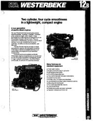
LOW VOLTAGE - ROTATING FIELD AUXILIARY WINDINGS TESTS<br />
A WARNING: Some of the following tests require the<br />
generator to be running, make certain the front pulley<br />
cover <strong>and</strong> timing belt covers are in place.<br />
ROTATING FIELD/AUXILIARY WINDINGS<br />
r------------------~<br />
• A '<br />
.~ :<br />
1iiiIQ~<br />
j<br />
L __________________ J<br />
TESTING THE DIODES<br />
If a distinct difference is noted in the ohm value, carefully<br />
unsolder the lead on the top of the diode <strong>and</strong> remove the<br />
diode from its isolated heat sink using a thin walled, deep<br />
well 7/16 in (II mm) socket.<br />
To check the diode, unsolder the connection from the top of<br />
the diode. Place one ohmmeter lead on the connection at the<br />
top of the diode <strong>and</strong> the other ohmmeter lead to the diode's<br />
base. Then reverse the position of the ohmmeter leads.<br />
lOW RESISTANCE (.)<br />
Description<br />
Two sets of windings are found in the rotor assembly. An AC<br />
voltage is produced in two groups of windings as the rotor<br />
turns at rated rpm. The AC voltage passes through each of<br />
the two diodes mounted on the isolated fixture just before the<br />
rotor carrier bearing. The AC sine wave is changed to a DC<br />
<strong>and</strong> tills DC voltage is passed through the two groups of<br />
rotating field windings producing a DC field around these<br />
windings. This field affects the AC winding of the two main<br />
stator groups inducing an AC voltage in these windings that<br />
is available at the AC terminal block connections.<br />
<strong>Testing</strong> The Windings Thru the Diodes<br />
To check the resistance values, rotate the engine's crankshaft<br />
to position the diode(s) on the generator's shaft at 12 o'clock.<br />
To make a quick check of these windings, presume the<br />
diode is OK <strong>and</strong> place one of the ohmmeter's leads on the<br />
connection at the top of the diode <strong>and</strong> the other lead at the<br />
connection at the base of the diode. Compare readings with<br />
the figures below.<br />
STANDARD RESISTANCE VALUES<br />
ROTATING FIELD I AUXILIARY WINDINGS<br />
Single Capacitor 3.8 Ohms<br />
Dual Capacitor 4.0 Ohms<br />
TESTING THE DIODES<br />
A low resistance should be found with the leads in one<br />
direction, <strong>and</strong> infinite resistance (blocking) in the other<br />
direction.<br />
DIODES 8 • 9.5 OHMS (APPROXIMATELY) USING A 260 SIMPSO/\<br />
ANALOG METER.<br />
NOTE: Different meter models may show different ohm<br />
values, but should read the same jar both diodes.<br />
DIODE RATING: 1600 AMPS 26 AMPS<br />
The diode's rating is far in excess of the circuit's requirements.<br />
Most likely a diode failure will result from an overspeed or<br />
load surge.<br />
A CAUTION: [ON SOLDERING] When soldering, use a<br />
large enough soldering iron to get the job done quickly.<br />
Excessive heat will damage the diodes.<br />
Also make certain no soldering splashes onto the<br />
windings as it will melt the insulation.<br />
~ WESTERBEKE<br />
Engines & Generators<br />
4
LOW VOLTAGE· ROTATING FIELD AUXILIARY WINDINGS TESTS<br />
<strong>Testing</strong> the Rotor Field Auxiliary Windings<br />
With the diode removed, both leads for the first group of<br />
rotating field/auxiliary windings will be isolated with no<br />
interference from a possibly faulty diode.<br />
Check the resistance value of the rotating windings by<br />
placing the ohmmeter's probes across the two exposed<br />
leads.<br />
ROTOR WINDINGS RESISTANCE VALUES<br />
Single Capacitor 3.8 ohms<br />
Dual Capacitor 4.0 ohms<br />
Dual Exciter Circuit 4.0 ohms<br />
<strong>Testing</strong> Continuity<br />
Check that no continuity exists between either of the winding<br />
leads <strong>and</strong> the generator shaft. If continuity is found,<br />
there is a short in the windings.<br />
Repeat the above tests on the second set of windings on<br />
the opposite side.<br />
TESTlNG THE WINDING LEADS<br />
TESTING FOR<br />
CONTINUITY<br />
[TEST BOTH LEADS]<br />
Engines & Generators<br />
5
RESIDUAL VOLTAGE - EXCITER CIRCUIT TESTS<br />
TESTING THE EXCITER WINDINGS<br />
AC voltage can be measured across the capacitor(s) while the<br />
generator is operating. This voltage may be as high as 400 to<br />
SOO volts AC. This voltage buildup is accomplished as the<br />
exciter windings charge the capacitor(s) <strong>and</strong> the capacitor(s)<br />
discharge back into the exciter windings. This AC voltage<br />
reading is taken between the #60 Hertz connector <strong>and</strong> the #<br />
connection plugged into the capacitor(s) while the generator<br />
is operating at its rated Hertz (60.S - 61.S for gasoline models<br />
<strong>and</strong> 61.S - 62.0 for diesel models). This flow of saturating<br />
AC in the exciter windings produces a phase-imbalance type<br />
of field that effects the auxiliary windings: a beneficial result<br />
that produces good motor starting characteristics for this type<br />
of generator.<br />
. SINGLE CAPACITOR<br />
c DUAl EXCITER<br />
DUAL CAPACITOR<br />
MEASURING<br />
ACVOLTAGE<br />
GENERATOR<br />
RUNNING<br />
Engines & Generators<br />
6
EXCITER CIRCUIT CAPACITOR(S) TESTS<br />
Measuring Resistance<br />
To measure the resistance of the exciter winding locate the<br />
#9 <strong>and</strong> the #50 Hertz capacitor connections.<br />
NOTE: Three numbered capacitor connections exist: #7, #8,<br />
<strong>and</strong> #9; <strong>and</strong> two Hertz connections #50 <strong>and</strong> #60.<br />
Unplug any other connections from the capacitor noting<br />
their position on the capacitor. Place one probe of the multimeter<br />
on plug connection #9 <strong>and</strong> the other probe on the<br />
50 Hertz lead. Measure the resistance value of the exciter<br />
windings <strong>and</strong> compare to the figures below.<br />
NOTE: Lower residual voltage along with a lower winding<br />
resistance will confirm a/aulty winding.<br />
EXCITER WINDINGS RESISTANCE<br />
Single Capacitor Dual Capacitor Dual Exciter 8CA Model<br />
1.9 ohms 2.2 ohms 1.3 ohms 1.5 ohms<br />
GENERATOR \!ll<br />
CASE<br />
CHECKING FOR<br />
CONTINUITY BETWEEN<br />
LEAD 50Hz & LEAO<br />
#9 TO CASE GROUND •<br />
-,~;:;:'<br />
... -","'"<br />
MEASURING RESISTANCE<br />
VALUE OF THHXCITER 11<br />
WINDINGS BETWEEN<br />
LEAOS 19 & 50Hz<br />
I~~~:~<br />
TESTING THE CAPACITORS ~:.<br />
_/ -<br />
d:: -~l<br />
~(I<br />
. i<br />
8/1 I i<br />
~ , ' .)J<br />
DISCHARGING<br />
THE CAPACITOR<br />
A WARNING: CapaCitors must be discharged before<br />
h<strong>and</strong>ling as they store electricity <strong>and</strong> can pack a potentially<br />
lethal charge even when disconnected from their<br />
power source.<br />
Discharge the capacitor by a bridging the terminals with an<br />
insulated screwdriver.<br />
Connect a multitester (highest ohm scale) to the capacitor terminals.<br />
The meter should go to zero ohms <strong>and</strong> slowly return<br />
to high. Discharge the capacitor again <strong>and</strong> reverse the leads,<br />
the same results should be obtained.<br />
If the meter goes down <strong>and</strong> stays at zero ohms, the capacitor<br />
is faulty (shorted) .<br />
If the meter fails to go down to zero, the capacitor is faulty<br />
(open circuited).<br />
Indications of a defective capacitor:<br />
D Infinite resistance, or no rise in resistance<br />
(shorted capacitor)<br />
D Infinite resistance (open capacitor)<br />
Checking Continuity<br />
CHECKING FOR<br />
CONTINUITY BETWEEN<br />
LEAO 50Hz ANO LEAO 19<br />
TO THE AC TERMINAL LEAOS<br />
Check to make sure there is no continuity to the<br />
ground/generator case from either of the two leads. Also<br />
check that no continuity exists between either the #50<br />
Hertz plug or the #9 plug <strong>and</strong> any of the main stator<br />
winding leads on the AC output. If continuity is found<br />
here, a fault exists between these two winding groups.<br />
An AC voltage is induced in these windings by the<br />
rotating field. Checking the residual voltage output from<br />
this winding can determine the condition of the winding<br />
when troubleshooting. Test between leads #50 <strong>and</strong> #9 with<br />
leads lifted off the capacitor(s).<br />
RESIDUAL VOLTAGE:<br />
Single Capacitor Model:<br />
Dual Exciter Model:<br />
Dual CapaCitor Model:<br />
10 -14 Volts AC from each winding<br />
7 - 9 Volts AC from each winding<br />
14 ·16 Volts AC from each winding<br />
AC<br />
TERMINAL<br />
BOARD<br />
CAPACITOR RATINGS<br />
Single Capacitor Models<br />
Dual Capacitor Models<br />
Dual Exciter Models<br />
MEASURING<br />
CAPACITOR<br />
RESISTANCE<br />
CAPACITOR<br />
CONNECTIONS<br />
25.0 MFD Pn#035985<br />
31.5 MFD Pn#035978<br />
18.0 MFIl Pn#039556<br />
NOTE: The older single capacitor models have 25.0 microfarad<br />
capacitors. New models now have 31.5 microfarad capacitors.<br />
Dual exciter models have Q 18.0 MFD capacity.<br />
The capacitor rating is marked on the housing of the capaciioT.<br />
Engines & Generators<br />
7
NO VOLTAGE OUTPUT· MAIN STATOR WINDINGS TESTS<br />
B<br />
NOTE: The studs on the AC terminal board are identified by<br />
the six red wire that attach to them. These wires are num~<br />
bered I thru 6. There are no numbers on the terminal block.<br />
EXCITING THE GENERATOR<br />
The generator may be excited using 12 volts DC taken<br />
from the engine's starting battery. This voltage is applied<br />
across the #50 <strong>and</strong> #9 leads of the exciter circuit windings<br />
(unplugged) with any other numbered leads unplugged<br />
from the capacitors. The generator's reaction
NO VOLTAGE OUTPUT - MAIN STATOR WINDINGS TESTS<br />
<strong>Testing</strong> Continuity<br />
There should not be any continuity between these two winding<br />
groups. Test between terminal #3 <strong>and</strong> tenninal #6. If continuity<br />
exists, there is a short in the windings.<br />
There also should be no continuity between the terminals <strong>and</strong><br />
the generator case (ground).<br />
MAIN STATOR<br />
WINDING LEADS<br />
TESTING CONTINUITY<br />
BETWEEN THE TWO<br />
WINDING GROUPS<br />
TESTING CONTINUITY<br />
EACH TERMINAL TO<br />
CASE GROUND<br />
,<br />
I<br />
I<br />
I<br />
I<br />
I<br />
I<br />
I<br />
I<br />
jI<br />
-.v WESTERBEKE<br />
Engines & Generators<br />
9
BATTERY CHARGING CIRCUIT I BRIDGE RECTIFIER<br />
TESTING THE BATTERY CHARGING CIRCUIT<br />
"- - -~------,<br />
DC CHARGE,<br />
I L ________________________________ oJ<br />
NOTE: The battery charging circuit is totally separate from the<br />
AC output afthe generator: The generator output affects the<br />
circuits output, but not the reverse.<br />
Nonnal AC voltage running to the rectifier (while the<br />
engine is operating at 1800 rpm) is measured across the<br />
two AC connections on the bridge rectifier (shown below).<br />
AC VOLTAGE TO THE BRIDGE RECTIFIER (APPROXIMATELY):<br />
No-load 011 the generator<br />
Full-load 011 the generator<br />
16.0 volts AC<br />
17.5 volts AC<br />
Nonnal DC voltage running out of the rectifier (in volts<br />
DC) is measured across the two DC connections of the<br />
bridge rectifier, that is + <strong>and</strong> - as illustrated.<br />
DC VOLTAGE FROM THE BRIDGE RECTIFIER (APPROXIMATELY):<br />
No-load 011 the generator<br />
Full-load 011 the generator<br />
17.0 volts DC<br />
18.5 volts DC<br />
Lift the two AC wire leads off the bridge rectifier <strong>and</strong><br />
measure the resistance between these two leads. It should<br />
measure 0.14 ohm. No continuity should exist between<br />
these two leads <strong>and</strong> the ground or the main stator windings.<br />
RESISTANCE BETWEEN AC LEADS 0.14 OHMS<br />
~,<br />
I -.........:..~<br />
, '''''........<br />
,N TESTING<br />
.-.'I~ CONTINUITY<br />
: , BETWEEN .J\~-~~~
INTEGRAL CONTROLLER I BALLAST RESISTOR<br />
INTEGRAL CONTROLLER 1 VOLT. ADJ POT<br />
~ ,~yyyy<br />
VOLT<br />
® + AC<br />
BRIDGE<br />
+ - GND RECTIFIER<br />
0<br />
BLACK<br />
YEllOW<br />
'- AC<br />
-~ INTEGRAL CONTROLLER<br />
GROUND<br />
-')<br />
INTEGRAL CONTROLLER (I.C.)<br />
The Integral Controller (I.e.) is an encapsulated, solid-state<br />
unit that supplies a DC charging voltage to the generator's<br />
starting battery while the generator is operating.<br />
Charging Voltage: 13.0 -14.0 Yolts DC<br />
Charging Amperage: 0 -10 amps DC [Early Models]<br />
Charging Amperage: 0 - 17 amps DC [Current Models]<br />
A separate group of stator windings supplies AC voltage to a<br />
bridge rectifier which converts the AC current to supply the<br />
I.C. unit. The I.e. unit senses the needs of the starting battery<br />
<strong>and</strong> supplies a DC charge when one is needed. If you suspect<br />
that the I.C. unit is faulty (that is, if the battery's charge is<br />
low), check the charging circuit <strong>and</strong> it's components as<br />
described in the following steps. Check all connections for<br />
cleanliness <strong>and</strong> tightness including the ground before replacing<br />
the I.e.. unit.<br />
NOTE: When the generator is first started, the I. C. unit will<br />
produce a low charging rate. This charging rate will rise as<br />
the generator is operated.<br />
The Integral Controller is mounted inside the generator housing<br />
in the 12:00 position. There is a voltage output adjustment<br />
on the controller that will allow a DC voltage output<br />
adjustment of ± 2 volts.<br />
DC CHARGE<br />
ISOLATOR<br />
TERMINAL 1:CI.....l;v~.,<br />
EARLIER MODEL<br />
INTEGRAL CONTROLLER<br />
THIS CONTROLLER PERFORMS THE<br />
SAME FUNCTION AS THE CURRENT<br />
MODEL CONTROLLERS.<br />
THE DC CHARGE ISOLATDR TERMINAL IS<br />
NO LONGER USEO. THE DC CHARGE LEAO<br />
GO'S DIRECTLY TO THE BATTERY TERMINAL<br />
ON THE STARTER SOLENOIO. STRIPEO<br />
WIRES ARE NOW SOLID COLORS.<br />
\\",dP\i""t~~<br />
. _II<br />
TO GROUNO TERMINAL<br />
BALLAST RESISTOR<br />
Early model integral controllers have a ballast resistor<br />
installed along the DC( +) lead running from the bridge rectifier<br />
to the integral controller. This coil-type resistor functions<br />
to suppress high amperage draw coming from the controller<br />
when it is trying to charge a discharged starting battery.<br />
BAllAST RESISTO~<br />
~ 50HZ-'<br />
r '::: 60Hz DC CHARGE<br />
~.<br />
1-----.lL..---~<br />
- =<br />
GNO<br />
EARLIER MODEL<br />
CAPACITOR ---I>-I//'<br />
BRIDGE<br />
RECTIFIER<br />
BALLAST RESISTOR<br />
0.3 OHM<br />
Measuring Resistance<br />
The resistance value of the ballast coil is measured between<br />
the lifted (+) lead at the bridge rectifier <strong>and</strong> the 60 Hertz<br />
connection unplugged from the controller (that is, controllers<br />
having plugs in the connector).<br />
Controllers with three leads corning from the controller<br />
measure resistance between the unplugged 60 Hertz<br />
connection at the bridge rectifier <strong>and</strong> the brown lead<br />
connection on the coil resistor tenninal block.<br />
NOTE: New four wire controllers eliminate the ballast resistor<br />
circuit since the ballast resistor s function is now h<strong>and</strong>led<br />
internally. Whenever replacing an early style controller with<br />
the newer four wire model, remove the ballast resistor <strong>and</strong> its<br />
wiring.<br />
«ilo
INTEGRAL CONTROLLER I NO-LOAD VOLTAGE ADJUSTMENT<br />
TESTING THE INTEGRAL CONTROLLER<br />
To test the battery charger, put a multimeter between the<br />
positive (+) <strong>and</strong> negative (-) leads to the battery. It should<br />
indicate l3.5V to l4V with the engine running. !f only the<br />
battery voltage is indicated, check that the battery charger<br />
terminal connections are tight. With the unit running, test<br />
between the (+) <strong>and</strong> (-) tenninals for l3.5V to l4Y. !fno<br />
charge is indicated, replace the charger.<br />
f GROUND<br />
II CONNECTION INTEGRAL CONTROLLER<br />
A WARNING: Capacitors must be discharged before<br />
h<strong>and</strong>ling as they store electricity <strong>and</strong> can pack a potential/y<br />
lethal charge even when disconnected from their<br />
power source_<br />
NOTE: Simply cross the capacitor s two tenninals with an insulated<br />
(plastic h<strong>and</strong>le) screwdriver. This will discharge any<br />
excess electricity.<br />
A WARNING: 00 not attempt to make a no-load<br />
voltage adjustment while the generator is operating.<br />
The capacitor can produce a 400-500 volt charge.<br />
Touching any wiring can produce a severe electrical<br />
shock. In addition, attempting to make a no-load voltage<br />
adjustment while the generator is operating could<br />
cause your fingers to be caught in the generator's rotor_<br />
FUSE PROTECTION<br />
-'-<br />
A 30 amp fuse protects the windings from a failure of the<br />
bridge rectifier or integral controller (high amperage or a<br />
short)<br />
SINGLE AND DUAL CAPACITOR NO-LOAD VOLTAGE<br />
ADJUSTMENT<br />
}, Remove the louvered metal plate, at the back of the<br />
generator, covering tile AC terminal connections <strong>and</strong><br />
the capacitor(s).<br />
2, Start the generator <strong>and</strong> allow it to run for approximately<br />
five minutes so the engine can warm up. Make sure the<br />
generator is oper.ating without any equipment drawing AC<br />
current from the generator (that is, shut off all electrical<br />
appliances). Make sure the engine's speed (Hertz) is<br />
correct. Adjust the governor as needed to obtain the<br />
correct engine speed before proceeding.<br />
3. Refer to the AC TERMINAL BOARD CONNECTIONS<br />
DIAGRAM for the correct configuration then check the<br />
generator's no-load voltage by measuring the voltage<br />
across the neutral lead <strong>and</strong> the hot lead with a voltmeter.<br />
Make sure you record this reading. The generator's noload<br />
voltage is lIS - 124 volts at 60.5 - 61.5 Hertz. If the<br />
voltage output is higher or lower than specified, proceed.<br />
4. Shut off the generator. Make sure the correct Hertz lead<br />
(60 Hertz #6, or 50 Hertz #5) is plugged into the<br />
capacitor(s).<br />
DUAL CAPACITOR<br />
c<br />
5. There are three plugs grouped for the right capacitor<br />
tenninal, #7, #8, <strong>and</strong> #9. If the generator's no-load voltage<br />
is low, then disconnect the lower numbered plug <strong>and</strong><br />
connect the plug with the next higher number. If the<br />
generator's no-load voltage is high, then disconnect the<br />
higher numbered plug <strong>and</strong> connect the plug with the next<br />
lower number. Note that the plug presently connected to<br />
this tenninal may.be anyone of the three plugs available.<br />
6. If the generator's no-load voltage cannot be adjusted<br />
because the voltage needs to be increased <strong>and</strong> the highest<br />
numbered plug is already connected to the right tenninal,<br />
or the voltage needs to be lowered <strong>and</strong> the lowest numbered<br />
plug is connected, refer to HERTZ ADJUSTMENT in the<br />
operators manual.<br />
::'i':!<br />
o 0<br />
~ ~<br />
!<br />
::'i':!#7#8#9<br />
THE CONNECTIONS<br />
SHOWN DEMONSTRATE<br />
HOW THESE AOJUSTMENTS<br />
CAN BE MADE<br />
SUHz 60Hz<br />
~_ WBTERSEKE<br />
#7 #8 #9 Engines & Generators<br />
12
NO-LOAD VOLTAGE ADJUSTMENT DUAL EXCITER<br />
DUAL EXCITER CIRCUIT MODEL<br />
These generators have dual Hertz <strong>and</strong> no-load voltage adjustment<br />
connectors at each capacitor. There are five connectors<br />
available for each capacitor. Two connectors are for Hertz<br />
selection, 60 Hertz or 50 Hertz, <strong>and</strong> three connectors, #7, #8,<br />
<strong>and</strong> #9, are for no-load voltage adjustment.<br />
When making Hertz change or no-load voltage adjustments<br />
proceed as follows:<br />
1. Shut the generator down.<br />
2. Select the appropriate Hertz connection to plug into each<br />
capacitor #60, 60 Hertz, 1800 RPM or #50 Hertz, 1500<br />
RPM. The three other connectors at each capacitor, #7,<br />
#8, <strong>and</strong> #9, will have an effect on the no-load voltage<br />
produced by the generator. One connector from each<br />
group can be plugged into each capacitor. No-load voltage<br />
will increase or decrease approximately 8 - 10 volts<br />
between connectors used in any pair combination to<br />
achieve the prescribed no-load voltage.<br />
C<br />
NOTE: When changing Hertz produced by the generatOl; {III<br />
engine speed adjustment at the governor must be made.<br />
The AC output connections on the terminal blocks must be<br />
selected for the voltage <strong>and</strong> Hem to be produced The<br />
Hertzp!ug connection at the capacitor must be changed/or<br />
50 Hem (#5) or 60 Hem (#6). Theframe ground wire<br />
must be moved when changing from 11 5 volts, 50 Hem to<br />
230 volts, 50 Hertz. Refer to the AC TERMINAL BOARD<br />
CONNECTIONS.<br />
3. On later model BC generators, a 50Hz/60Hz connection<br />
is provided for the DC battery circuit. When changing<br />
hertz, connect the proper lead (50Hz or 60Hz) to the<br />
bridge rectifier.<br />
50Hz #7 #8 #9 50Hz 60Hz #8 #9<br />
~t---1<br />
~r----l<br />
BATTERY CIRCUIT<br />
CONNECTIONS 5O/60Hz<br />
[CURRENT MODELS]<br />
A WARNING: Make certain the insulating covers on<br />
the unused leads are in place <strong>and</strong> are NOT in contact<br />
with each other or in contact with the generator's<br />
housing.<br />
AC CONNECTION<br />
Engines & Generators<br />
13
1033 WM/DW 3/2000<br />
Engines & Generators