AS-Scientific SIVL PDF - Asistec
AS-Scientific SIVL PDF - Asistec
AS-Scientific SIVL PDF - Asistec

You also want an ePaper? Increase the reach of your titles
YUMPU automatically turns print PDFs into web optimized ePapers that Google loves.
-------------------------------------------<br />
INTRODUCTION TO <strong>SIVL</strong><br />
-------------------------------------------<br />
(1 of 7)<br />
…for the transfer of Liquefied Gases and Extreme<br />
Temperature Fluids<br />
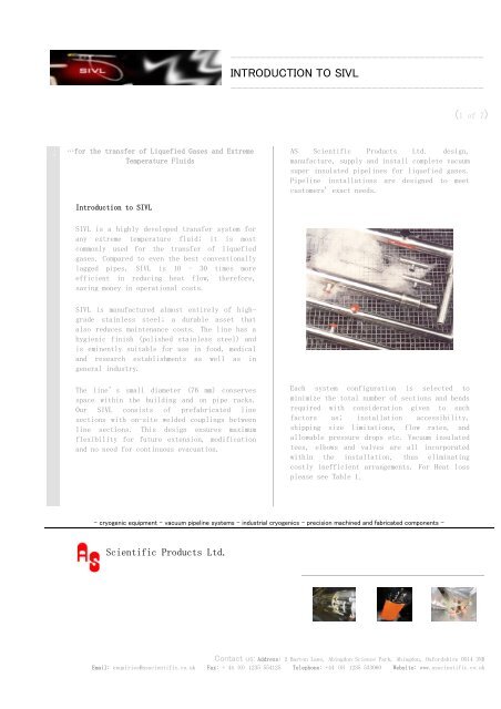
<strong>AS</strong> <strong>Scientific</strong> Products Ltd. design,<br />
manufacture, supply and install complete vacuum<br />
super insulated pipelines for liquefied gases.<br />
Pipeline installations are designed to meet<br />
customers' exact needs.<br />
Introduction to <strong>SIVL</strong><br />
<strong>SIVL</strong> is a highly developed transfer system for<br />
any extreme temperature fluid; it is most<br />
commonly used for the transfer of liquefied<br />
gases. Compared to even the best conventionally<br />
lagged pipes, <strong>SIVL</strong> is 10 - 30 times more<br />
efficient in reducing heat flow, therefore,<br />
saving money in operational costs.<br />
<strong>SIVL</strong> is manufactured almost entirely of highgrade<br />
stainless steel; a durable asset that<br />
also reduces maintenance costs. The line has a<br />
hygienic finish (polished stainless steel) and<br />
is eminently suitable for use in food, medical<br />
and research establishments as well as in<br />
general industry.<br />
The line’s small diameter (76 mm) conserves<br />
space within the building and on pipe racks.<br />
Our <strong>SIVL</strong> consists of prefabricated line<br />
sections with on-site welded couplings between<br />
line sections. This design ensures maximum<br />
flexibility for future extension, modification<br />
and no need for continuous evacuation.<br />
Each system configuration is selected to<br />
minimize the total number of sections and bends<br />
required with consideration given to such<br />
factors as; installation accessibility,<br />
shipping size limitations, flow rates, and<br />
allowable pressure drops etc. Vacuum insulated<br />
tees, elbows and valves are all incorporated<br />
within the installation, thus eliminating<br />
costly inefficient arrangements. For Heat loss<br />
please see Table 1.<br />
- cryogenic equipment - vacuum pipeline systems - industrial cryogenics - precision machined and fabricated components -<br />
<strong>Scientific</strong> Products Ltd.<br />
Contact us: Address: 2 Barton Lane, Abingdon Science Park, Abingdon, Oxfordshire OX14 3NB<br />
Email: enquiries@asscientific.co.uk Fax: + 44 (0) 1235 554125 Telephone: +44 (0) 1235 533060 Website: www.asscientific.co.uk
-------------------------------------------<br />
HEAT LOSS<br />
-------------------------------------------<br />
(2 of 7)<br />
Table 1: Heat Loss of the <strong>SIVL</strong><br />
Tube---- -Watts Meter-- Elbow--- Tee---Welded joint---_Bayonet connection<br />
15 mm Tube------0.16------0.24---- 0.24------1.50---------------1.50<br />
1" Tube-------- 0.26------0.38---- 0.39------2.53---------------2.50<br />
1" Pipe---------0.35------0.50---- 0.51------2.53---------------2.50<br />
1½”Tube--------0.40------0.56-----0.56------3.10---------------3.00<br />
1½" Pipe--------0.50------0.71-----0.71------3.10---------------3.00<br />
This unique feature minimizes heat - leak,<br />
reduces frosting and allows for rapid<br />
disconnection of the line.<br />
In addition, bayonet connections provide an<br />
economic method of joining vacuum-insulated<br />
transfer lines. They allow for liquid savings<br />
because of low heat influx, decreased<br />
installation time, and lower field installation<br />
costs. Once installed, they require no<br />
maintenance, and the insulation suffers no<br />
deterioration during operation regardless of<br />
where the pipeline is installed.<br />
Design<br />
Maximum Operating Pressure = 10.5 bar<br />
Bayonet connections<br />
The bayonet connection is a close tolerance fit<br />
between male and female, forming a thin<br />
cylindrical cavity. During cryogenic transfer,<br />
gas from the process liquid is vaporized in the<br />
long narrow cavity forming a vapour seal, which<br />
is at process stream temperature at one end and<br />
ambient temperature at the other. The vapour<br />
seal isolates the mechanical seal from the<br />
cryogenic temperatures.<br />
Rigid pipelines<br />
Rigid pipelines are the best for getting optimum<br />
quality of the liquid cryogen. In some cases it<br />
cannot be avoided that flexible parts have to be<br />
used. This leads to deterioration in the liquid<br />
quality as the corrugations cause a much higher<br />
pressure drop along the pipeline. Furthermore,<br />
the investment costs are much higher. <strong>AS</strong><br />
<strong>Scientific</strong> Products Ltd. do supply flexible<br />
sections in the pipeline, however, only if<br />
absolutely necessary. To improve the quality of<br />
the liquid cryogen further, other provisions can<br />
be incorporated in the system such as phase<br />
separators, gas vents or subcoolers.<br />
- cryogenic equipment - vacuum pipeline systems - industrial cryogenics - precision machined and fabricated components -<br />
________________________________________________________________________________________________________<br />
<strong>Scientific</strong> Products Ltd.<br />
Contact us: Address: 2 Barton Lane, Abingdon Science Park, Abingdon, Oxfordshire OX14 3NB<br />
Email: enquiries@asscientific.co.uk Fax: + 44 (0) 1235 554125 Telephone: +44 (0) 1235 533060 Website: www.asscientific.co.uk
-------------------------------------------<br />
INTRODUCTION TO <strong>SIVL</strong><br />
-------------------------------------------<br />
(3 of 7)<br />
Cooling capability of nitrogen<br />
About 50% of the cooling capability of liquid<br />
nitrogen results from liquid boiling to vapour.<br />
Getting the nitrogen to the point of use as a<br />
liquid is therefore important.<br />
Liquid nitrogen is delivered to the point of<br />
use by maintaining the storage tank at an<br />
elevated pressure. System heat leak frequently<br />
causes the pressurized liquid to become<br />
saturated at this elevated pressure. As the<br />
liquid flows from the tank in a normally<br />
horizontal delivery line, it begins to boil<br />
since it is flowing to a point of lower<br />
pressure. The fluid, now in two-phase flow,<br />
causes a pressure drop substantially greater<br />
than the pressure loss, which would result from<br />
the same mass flow as 100 % liquid. The<br />
increased line pressure loss causes even more<br />
vapour to be formed and the loss of compounds<br />
themselves.<br />
As the boiling two-phase liquid reaches the end<br />
valve, the pressure is further reduced and the<br />
vapour component is increased, resulting in<br />
liquid / vapour pulsations.<br />
Flexibility of the line<br />
Each coupling provides access to the existing<br />
line<br />
…for additional drops or feeds to other<br />
equipment. These additional feeds are taken off<br />
without affecting the main line section vacuums.<br />
Similar, the line can be cut back to a coupling<br />
and rerouted without affecting the vacuum in the<br />
remaining line sections. When no longer required,<br />
the line can be dismantled and used elsewhere.<br />
Installation Advantages<br />
Short installation time.<br />
For manufacturing and physical reasons all<br />
transfer line installations are built in<br />
sections. From the insulation aspect, each<br />
section of the line is a sealed unit and<br />
therefore, to maintain continuity of insulation,<br />
the couplings between each section have been<br />
designed as bayonets with extremely low heat leak<br />
characteristics. They enable quick installation<br />
and disconnection, and solve special performance<br />
requirements in the vacuum insulated cryogenic<br />
transfer lines. A 50 - 60 m line is installed in<br />
two to three days depending on how easily the<br />
line hangers can be reached. No external<br />
insulation required, therefore, the start time is<br />
reduced. Liquid gas is flowing 4 hours after<br />
completion of the last weld.<br />
- cryogenic equipment - vacuum pipeline systems - industrial cryogenics - precision machined and fabricated components -<br />
<strong>Scientific</strong> Products Ltd.<br />
Contact us: Address: 2 Barton Lane, Abingdon Science Park, Abingdon, Oxfordshire OX14 3NB<br />
Email: enquiries@asscientific.co.uk Fax: + 44 (0) 1235 554125 Telephone: +44 (0) 1235 533060 Website: www.asscientific.co.uk
-------------------------------------------<br />
INTRODUCTION<br />
-------------------------------------------<br />
(4 of 7)<br />
Servicing Advantages<br />
The line is virtually maintenance free (no<br />
crumbling insulation to be replaced every year<br />
or so). Any deterioration in vacuum will only<br />
affect that section and not the whole line.<br />
Losses to the system<br />
In the supply line, there are several kinds of<br />
losses to the system as follows:<br />
Straight line pressure drop. This is a<br />
function of _____flow rate, line length, line<br />
diameter and liquid in _____the tank. A system<br />
which is expected to deliver _____comparatively<br />
'warm' liquid to the supply line _____should<br />
have a larger bore to attain the same<br />
_____pressure drop and flow rate. On the other<br />
hand, _____alternate surges of vapour and<br />
liquid usually _____result from an oversized<br />
line.<br />
Losses caused by turbulence in elbows and<br />
tees.<br />
Cool down losses. This depends upon type of<br />
_____line used and is a linear function of<br />
diameter _____and length.<br />
Hydrostatic head losses. If the flowing<br />
liquid is _____at its boiling point, there can<br />
be no syphon _____effect so there will be no<br />
recovery of upward _____heat loss on downward<br />
runs. Each vertical _____meter of upward run is<br />
equivalent to a line _____length of about 10<br />
horizontal meters. _____Unavoidable vertical<br />
runs should be placed as _____far downstream as<br />
possible to minimize the _____compounded effects<br />
of two phase flow.<br />
Insulation or steady state losses. These<br />
losses _____are a function of the flow through<br />
the line and _____total heat leak through the<br />
insulation. Although _____this heat leak applies<br />
mostly to overall system _____thermal<br />
efficiency, it also can affect line<br />
_____pressure drop where it contributes<br />
appreciably _____to the generation of vapour and<br />
two-phase flow _____in the line.<br />
Size Range of Line Sections<br />
Line sections are made in lengths up to a<br />
maximum of 6 m and have a standard 16 gauge<br />
polished stainless outer tube of diameter 76.2<br />
mm. The inner tube size is chosen for the<br />
required flow of liquid gas.<br />
- cryogenic equipment - vacuum pipeline systems - industrial cryogenics - precision machined and fabricated components -<br />
________________________________________________________________________________________________________<br />
<strong>Scientific</strong> Products Ltd.<br />
Contact us: Address: 2 Barton Lane, Abingdon Science Park, Abingdon, Oxfordshire OX14 3NB<br />
Email: enquiries@asscientific.co.uk Fax: + 44 (0) 1235 554125 Telephone: +44 (0) 1235 533060 Website: www.asscientific.co.uk
-------------------------------------------<br />
INTRODUCTION<br />
-------------------------------------------<br />
(5 of 7)<br />
Construction and Testing<br />
Super insulation is applied in clean factory<br />
conditions and sealed in each line section<br />
prior to shipment. Line sections are evacuated<br />
in the factory using large diffusion pumps<br />
fitted with liquid nitrogen cold traps or<br />
turbomolecular pumps. With this method, the<br />
line sections can be mounted directly on a pump<br />
giving a maximum pumping path length of 3.5 m.<br />
Even so, pumping times of seven days are normal<br />
to reduce the outgassing rate to an acceptable<br />
level.<br />
Photographs of a typical handler installation<br />
in the semiconductor industry<br />
After satisfactory completion of pumping, each<br />
line section is helium leak tested, using a<br />
mass spectrometer, to
-------------------------------------------<br />
INTRODUCTION<br />
-------------------------------------------<br />
(6 of 7)<br />
Line Section<br />
Welded Coupling<br />
- cryogenic equipment - vacuum pipeline systems - industrial cryogenics - precision machined and fabricated components -<br />
________________________________________________________________________________________________________<br />
<strong>Scientific</strong> Products Ltd.<br />
L________________________________________<br />
Contact us: Address: 2 Barton Lane, Abingdon Science Park, Abingdon, Oxfordshire OX14 3NB<br />
Email: enquiries@asscientific.co.uk Fax: + 44 (0) 1235 554125 Telephone: +44 (0) 1235 533060 Website: www.asscientific.co.uk
-------------------------------------------<br />
BAYONET <strong>AS</strong>SEMBLY<br />
-------------------------------------------<br />
(7 of 7)<br />
Contact us: Address: 2 Barton Lane, Abingdon Science Park, Abingdon, Oxfordshire OX14 3NB<br />
Email: enquiries@asscientific.co.uk Fax: + 44 (0) 1235 554125 Telephone: +44 (0) 1235 533060 Website: www.asscientific.co.uk