CORREVIT® S-350 Aqua USER MANUAL VOLUME I - Corrsys-Datron
CORREVIT® S-350 Aqua USER MANUAL VOLUME I - Corrsys-Datron
CORREVIT® S-350 Aqua USER MANUAL VOLUME I - Corrsys-Datron

Create successful ePaper yourself
Turn your PDF publications into a flip-book with our unique Google optimized e-Paper software.
User Manual<br />
CORREVIT ® S-<strong>350</strong> Sensor<br />
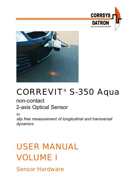
CORREVIT ® S-<strong>350</strong> <strong>Aqua</strong><br />
non-contact<br />
2-axis Optical Sensor<br />
for<br />
slip free measurement of longitudinal and transversal<br />
dynamics<br />
<strong>USER</strong> <strong>MANUAL</strong><br />
<strong>VOLUME</strong> I<br />
Sensor Hardware<br />
© 2008 CORRSYS-DATRON Sensorsysteme GmbH, Wetzlar S-<strong>350</strong>_m-640-p1-e-rev001 10/08 1
User Manual<br />
CORREVIT ® S-<strong>350</strong> Sensor<br />
Note: For a general description of the CeCalWin Pro Software refer<br />
to the separate user manual Volume II.<br />
For the specific software description for the S-<strong>350</strong> Sensor<br />
refer to the separate user manual Volume III.<br />
© 2008 CORRSYS-DATRON Sensorsysteme GmbH, Wetzlar S-<strong>350</strong>_m-640-p1-e-rev001 10/08 2
User Manual<br />
CORREVIT ® S-<strong>350</strong> Sensor<br />
<strong>VOLUME</strong> I - Sensor Hardware<br />
Table of Contents<br />
General Information . . . . . . . . . . . . . . . . . . . . . . . . . . . . . . . . . . . . . . . . . . . .4<br />
Safety Instructions . . . . . . . . . . . . . . . . . . . . . . . . . . . . . . . . . . . . . . . . . . . . .5<br />
1. Overview . . . . . . . . . . . . . . . . . . . . . . . . . . . . . . . . . . . . . . . . . . . . . . . . . .6<br />
2. Extent of Delivery . . . . . . . . . . . . . . . . . . . . . . . . . . . . . . . . . . . . . . . . . .8<br />
3. Technical Data . . . . . . . . . . . . . . . . . . . . . . . . . . . . . . . . . . . . . . . . . . . .10<br />
3.1 Specifications . . . . . . . . . . . . . . . . . . . . . . . . . . . . . . . . . . . . . . . . . . .10<br />
3.2 Pin Assignments . . . . . . . . . . . . . . . . . . . . . . . . . . . . . . . . . . . . . . . . .11<br />
3.3 Default-Settings for Analog and Digital Outputs . . . . . . . . . . . . . . . . . .13<br />
3.3.1 Analog Output Default Settings . . . . . . . . . . . . . . . . . . . . . . .13<br />
3.3.2 Digital Output Default Settings . . . . . . . . . . . . . . . . . . . . . . . .13<br />
3.4 Internal Signal Filtering . . . . . . . . . . . . . . . . . . . . . . . . . . . . . . . . . . . .14<br />
3.4.1 Moving Average Filter . . . . . . . . . . . . . . . . . . . . . . . . . . . . . . .14<br />
3.4.2 FIR Filter . . . . . . . . . . . . . . . . . . . . . . . . . . . . . . . . . . . . . . . .14<br />
4. Set-up and Connection . . . . . . . . . . . . . . . . . . . . . . . . . . . . . . . . . . . .15<br />
4.1 Mounting Options . . . . . . . . . . . . . . . . . . . . . . . . . . . . . . . . . . . . . . . .15<br />
4.2 Sensor Mounting Jig . . . . . . . . . . . . . . . . . . . . . . . . . . . . . . . . . . . . .15<br />
4.3 Mounting Instructions . . . . . . . . . . . . . . . . . . . . . . . . . . . . . . . . . . . . .16<br />
4.3.1 Installation with Suction Holder for Front Mounting . . . . . . . . .16<br />
4.3.2 Installation with Magnetic Pate Holder at the Vehicle Side . . . .21<br />
4.4 Connecting the Sensor . . . . . . . . . . . . . . . . . . . . . . . . . . . . . . . . . . . .24<br />
5. Trouble Shooting . . . . . . . . . . . . . . . . . . . . . . . . . . . . . . . . . . . . . . . . . .25<br />
Appendix A:<br />
Technical Drawing<br />
Appendix B: Mounting Photo S-<strong>350</strong><br />
Installation with Suction Holder<br />
for Front Mounting<br />
Appendix C: Mounting Photo S-<strong>350</strong><br />
Installation with Magnetic Plate Holder<br />
for Mounting at the Vehicle Side<br />
CORREVIT ® is a registered trademark of CORRSYS-DATRON Sensorsysteme GmbH, Wetzlar Germany. In a continuous effort to<br />
improve our products CORRSYS-DATRON reserves the right to change specifications without prior notice.<br />
© 2008 CORRSYS-DATRON Sensorsysteme GmbH, Wetzlar S-<strong>350</strong>_m-640-p1-e-rev001 10/08 3
User Manual<br />
General Information<br />
CORREVIT ® S-<strong>350</strong> Sensor<br />
Legal Notice<br />
Information furnished is believed to be accurate and reliable. However, CORRSYS-DATRON assumes<br />
no responsibility for the consequences of use of such information nor for any infringement of patents<br />
or other rights of third parties which may result from its use. No license is granted by implication or<br />
otherwise under any patent or patent rights of CORRSYS-DATRON. Specifications mentioned in this<br />
publication are subject to change without notice and do not represent a commitment on the part of<br />
CORRSYS-DATRON. This publication supersedes and replaces all information previously supplied.<br />
All brand names are trademarks of their respective holders.<br />
Copyright<br />
©Copyright 2008, CORRSYS-DATRON<br />
Revision<br />
S-<strong>350</strong>_m-640-p1-e-rev001 10/08<br />
Contact<br />
International Headquarters:<br />
CORRSYS-DATRON Sensorsysteme GmbH<br />
Charlotte-Bamberg-Str. 12<br />
35578 Wetzlar / Germany<br />
Phone ++49 (6441) 9282-0<br />
Hotline ++49 (6441) 9282-82<br />
Fax ++49 (6441) 9282-17<br />
E-mail sales@corrsys-datron.com<br />
URL www.corrsys-datron.com<br />
North American Headquarters:<br />
CORRSYS-DATRON Sensorsystems, Inc.<br />
40000 Grand River, Suite 503<br />
Novi, MI 48375 / USA<br />
Phone ++1 (248) 615-2035<br />
Toll-free++1 (800) 832-0732<br />
Fax ++1 (248) 615-2184<br />
E-mail USA-sales@corrsys-datron.com<br />
URL www.corrsys-datron.com<br />
China Headquarters:<br />
CORRSYS-DATRON Sensorsysteme GmbH, China Office<br />
Room 708, JinTianDi International Mansion,<br />
No. 998 RenMin Road, Shanghai (200021), P.R.China<br />
Tel.: ++86-21-63114144<br />
Fax: ++86-21-63114154<br />
E-mail: Xiaoying.Li@corrsys-datron.com.cn<br />
URL: www.corrsys-datron.com.cn<br />
© 2008 CORRSYS-DATRON Sensorsysteme GmbH, Wetzlar S-<strong>350</strong>_m-640-p1-e-rev001 10/08 4
User Manual<br />
Safety Instructions<br />
CORREVIT ® S-<strong>350</strong> Sensor<br />
Please read carefully before operating the equipment.<br />
CORRSYS-DATRON is not responsible for damage that may occur when this system is used in<br />
any way other than that for which it is intended.<br />
To assure safe and proper operation, all supplied equipment, components and/or accessories must be<br />
carefully transported and stored, as well as professionally installed and operated. Careful maintenance<br />
and usage in full accordance with operating instructions is imperative.<br />
CORRSYS-DATRON equipment should be installed and operated only by qualified persons who are<br />
familiar with devices of this type.<br />
Local regulations may not permit the operation of motor vehicles on public highways while the<br />
equipment is mounted on the exterior of the vehicle.<br />
• Use the equipment only for intended applications. Improper application is not advised.<br />
• Do not modify or change the equipment or its accessories in any way.<br />
• Improper use or mounting of the equipment may affect the safety of the vehicle and/or occupants.<br />
• The equipment must not be mounted and/or operated in any way that may compromise vehicle or<br />
and/or occupant safety.<br />
• Equipment must be mounted firmly and securely.<br />
• Use only original equipment, components and/or accessories included in the scope of delivery.<br />
• Do not mount equipment, components and/or accessories near heat sources (e.g. exhaust).<br />
• Do not use defective or damaged equipment, components and/or accessories .<br />
• Always note correct pin assignments and operating voltages when connecting equipment to<br />
power supplies, data acquisition/evaluation systems, and/or any other applicable system or<br />
component. Equipment may be damaged if not properly connected and/or operated.<br />
• For additional information, please call the CORRSYS-DATRON Hotline: ++49 (6441) 9282-82<br />
or email: hotline@corrsys-datron.com.<br />
Danger<br />
Warning<br />
• Use caution when exchanging sensor lamps – lamps are extremely hot, and may cause injury.<br />
• Do not look into sensor lamps – lamps are extremely bright, and may cause eye injury.<br />
• Sensor head can become very hot and may cause injury if power has been applied to the<br />
sensor for extended periods of time. This is especially true if the sensor is used in hot<br />
environmental conditions.<br />
• The sensor and/or sensor components may be damaged if power is applied for extended<br />
periods, especially in hot environmental conditions.<br />
• To avoid damage to the sensor lens, please do only clean it with a micro-fiber cloth.<br />
• Disconnect power from the sensor if the vehicle is stationary for extended periods.<br />
© 2008 CORRSYS-DATRON Sensorsysteme GmbH, Wetzlar S-<strong>350</strong>_m-640-p1-e-rev001 10/08 5
User Manual<br />
CORREVIT ® S-<strong>350</strong> Sensor<br />
1. Overview<br />
CORREVIT ®<br />
S-<strong>350</strong> <strong>Aqua</strong><br />
Non-Contact 2-Axis<br />
Optical Sensor<br />
for<br />
slip-free measurement of<br />
longitudinal and transversal<br />
dynamics<br />
Art. No.<br />
S-<strong>350</strong> <strong>Aqua</strong> longitudinal 15377<br />
S-<strong>350</strong> <strong>Aqua</strong> transversal 15378<br />
The new CORREVIT ® S-<strong>350</strong> <strong>Aqua</strong> Optical Sensor represents yet another step<br />
forward in the advancement of optical measurement technology. It produces<br />
unparalleled accuracy, even under the most challenging conditions.<br />
Compact and lightweight, the S-<strong>350</strong> <strong>Aqua</strong> Sensor can be mounted in seconds, and<br />
features the latest advanced spectral/optical filters, state-of-the-art digital signal<br />
processing and surface-adaptive illumination.<br />
Speed and distance information is updated at 250 Hz to track every highly dynamic<br />
maneuver.<br />
The extended working range of the CORREVIT ® S-<strong>350</strong> <strong>Aqua</strong> Sensor makes it ideal for<br />
measurement of transversal dynamics with trucks, busses and off-road vehicles.<br />
© 2008 CORRSYS-DATRON Sensorsysteme GmbH, Wetzlar S-<strong>350</strong>_m-640-p1-e-rev001 10/08 6
User Manual<br />
CORREVIT ® S-<strong>350</strong> Sensor<br />
Features<br />
• CORREVIT ® S-<strong>350</strong> <strong>Aqua</strong> with working range of <strong>350</strong> ±100 mm<br />
• Applicable from 0.5 kph ... 250 kph*<br />
• Due to its considerably extended working range, the S-<strong>350</strong> <strong>Aqua</strong> Sensor is<br />
ideally suited for application with trucks, busses and off-road vehicles.<br />
• Sensor Electronics provide option for connection of a Gyro to attain yaw rate for<br />
measurement of sideslip angle relative to the vehicle´s center of gravity<br />
• Adjustable filter time (unfiltered, 8 ... 512 ms)<br />
FIR Filter with constant filter time (adjustable)<br />
Considerably improved performance is enabled by the application of the latest technologies:<br />
Latest halogen lamp with aluminum reflector<br />
Smallest dimensions<br />
Improved distance linearity,<br />
Easier mounting<br />
Improved signal processing by ideal combination of the analog and digital signal<br />
conditioning (DSP-FPGA technology).<br />
Reduced noise of the output signal<br />
Improved measurement features on various surfaces<br />
Improved standstill<br />
Quick filter start-up<br />
• Extremely high measuring accuracy** better than ±0.1% as a result of precise optics<br />
and digital signal processing.<br />
• Programmable standard analog and digital signal outputs<br />
• All measured values available<br />
• Direct connection to PC and virtually all data acquisition systems<br />
Signal outputs: Analog<br />
Digital<br />
CAN Bus V 2.0B<br />
USB or RS232<br />
• Negligible service and maintenance requirements as a result of durable technology<br />
• Tested and used under extreme environmental conditions<br />
Application<br />
The compact, low-weight CORRSYS-DATRON S-<strong>350</strong> <strong>Aqua</strong> Sensor is designed for<br />
application in dynamic vehicle tests, which require precise measurement of the following<br />
parameters:<br />
• Distance<br />
• Speed (longitudinal and transversal dynamics)<br />
• Angle<br />
* optional: calibrated up to 400 kph<br />
** with calibration on the test surface<br />
© 2008 CORRSYS-DATRON Sensorsysteme GmbH, Wetzlar S-<strong>350</strong>_m-640-p1-e-rev001 10/08 7
User Manual<br />
CORREVIT ® S-<strong>350</strong> Sensor<br />
2. Extent of Delivery<br />
11<br />
3<br />
4<br />
16<br />
15<br />
1<br />
5<br />
18<br />
13<br />
6<br />
7<br />
8<br />
14<br />
17<br />
9<br />
2<br />
12<br />
10<br />
Standard Extent of delivery for Art.no. 15377 - S-<strong>350</strong> <strong>Aqua</strong> longitudinal<br />
1. (1) 15714 Sensor head S-<strong>350</strong> longitudinal<br />
2. (1) 15248 Sensor Electronics L-<strong>350</strong> <strong>Aqua</strong> / S-<strong>350</strong> <strong>Aqua</strong><br />
3. (1) 14862 Sensor cable, 5m, MIL, small version, #K-003-1J2-12-5m<br />
4. (1) 10413 Power cable, 2m, MIL 6P banana plug, #K-003-16N-12-2m<br />
5. (1) 13946 CAN cable 2m 3P Binder 9pin Sub-D, #K-030-14N-10-2m<br />
5. (1) 13425 PC cable RS232 2m 4P Binder -> 9P Sub-D for HT500, RV4 and L-400 Brake,<br />
L-<strong>350</strong>, MSW processor II, RV3 processor II; #K045-14N-10-2m<br />
7. (1) 10527 1m, 5xBNC, S-400, HS-CE, SL, #K003-592-11-1m<br />
8. (1) 13947 Cable USB 2m ->4P Binder, #K-041-14N-20-2 m<br />
9. (1) 14893 Halogen lamp 20W/12V for L-<strong>350</strong> <strong>Aqua</strong> / S-<strong>350</strong><br />
10. (1) 15176 Plastic transport case, black, 545x405x120 mm<br />
11. (1) 15182 Foam insole for transport case L-<strong>350</strong> <strong>Aqua</strong> / S-<strong>350</strong><br />
12. (1) 15478 Foam insole for transport case L-<strong>350</strong> <strong>Aqua</strong> / S-<strong>350</strong><br />
13. (1) 15271 Spray guard L-<strong>350</strong> <strong>Aqua</strong> / S-<strong>350</strong><br />
14. (1) 15437 Tool to exchange the Sensor halogen lamp<br />
15. (1) 15436 Screw Driver Torx<br />
16. (1) 14283 Allen wrench 4mm<br />
17. (1) 14643 Mini folding rule<br />
18. (1) 11343 Software CeCalWin Pro<br />
19. (1) 11427 Calibration of a Sensor with DIN EN ISO 9001 manufacturer certificate type "M" to<br />
DIN 55<strong>350</strong>, part 18 for all 2-axis optical sensors<br />
© 2008 CORRSYS-DATRON Sensorsysteme GmbH, Wetzlar S-<strong>350</strong>_m-640-p1-e-rev001 10/08 8
User Manual<br />
CORREVIT ® S-<strong>350</strong> Sensor<br />
Standard Extent of Delivery for Art.no. 15378 - S-<strong>350</strong> <strong>Aqua</strong> transversal<br />
(see photo on page 8)<br />
1. (1) 15713 Sensor head S-<strong>350</strong> transversal<br />
2. (1) 15248 Sensor Electronics L-<strong>350</strong> <strong>Aqua</strong> / S-<strong>350</strong> <strong>Aqua</strong><br />
3. (1) 14862 Sensor cable, 5m, MIL, small version, #K-003-1J2-12-5m<br />
4. (1) 10413 Power cable, 2m, MIL 6P banana plug, #K-003-16N-12-2m<br />
5. (1) 13946 CAN cable 2m 3P Binder 9pin Sub-D, #K-030-14N-10-2m<br />
5. (1) 13425 PC cable RS232 2m 4P Binder -> 9P Sub-D for HT500, RV4 and L-400 Brake,<br />
L-<strong>350</strong>, MSW processor II, RV3 processor II; #K045-14N-10-2m<br />
7. (1) 10527 1m, 5xBNC, S-400, HS-CE, SL, #K003-592-11-1m<br />
8. (1) 13947 Cable USB 2m ->4P Binder, #K-041-14N-20-2 m<br />
9. (1) 14893 Halogen lamp 20W/12V for L-<strong>350</strong> <strong>Aqua</strong> / S-<strong>350</strong><br />
10. (1) 15176 Plastic transport case, black, 545x405x120 mm<br />
11. (1) 15182 Foam insole for transport case L-<strong>350</strong> <strong>Aqua</strong> / S-<strong>350</strong><br />
12. (1) 15478 Foam insole for transport case L-<strong>350</strong> <strong>Aqua</strong> / S-<strong>350</strong><br />
13. (1) 15271 Spray guard L-<strong>350</strong> <strong>Aqua</strong> / S-<strong>350</strong><br />
14. (1) 15437 Tool to exchange the Sensor halogen lamp<br />
15. (1) 15436 Screw Driver Torx<br />
16. (1) 14283 Allen wrench 4mm<br />
17. (1) 14643 Mini folding rule<br />
18. (1) 11343 Software CeCalWin Pro<br />
19. (1) 11427 Calibration of a Sensor with DIN EN ISO 9001 manufacturer certificate type "M" to<br />
DIN 55<strong>350</strong>, part 18 for all 2-axis optical sensors<br />
About replacement halogen lamps<br />
It is recommended that only halogen lamps<br />
supplied by CORRSYS-DATRON be used as<br />
these have been subjected to a special treatment.<br />
Optimal sensor function can only be assured<br />
when using original-equipment lamps.<br />
© 2008 CORRSYS-DATRON Sensorsysteme GmbH, Wetzlar S-<strong>350</strong>_m-640-p1-e-rev001 10/08 9
User Manual<br />
CORREVIT ® S-<strong>350</strong> Sensor<br />
3. Typical Technical Data<br />
3.1 Specifications<br />
Performance specifications<br />
Speed range: 0.5 ... 250 kph *<br />
Distance resolution:<br />
2.47 mm<br />
Distance measurement deviation:
User Manual<br />
CORREVIT ® S-<strong>350</strong> Sensor<br />
3.2 Pin Assignments<br />
4<br />
CAN 3 pin Binder 718 flange, male<br />
Pin 1: CAN high<br />
Pin 3: CAN low<br />
Pin 4: CAN-GND<br />
1<br />
3<br />
2 4<br />
1<br />
3<br />
USB 4 pin Binder 718 flange, female<br />
Pin 1: D+<br />
Pin 2: D-<br />
Pin 3: DGND<br />
Pin 4: Switch<br />
2 4<br />
1 3<br />
continued next page...<br />
RS-232 4 pin Binder 718 flange, male<br />
Pin 1: TX<br />
Pin 2: RX<br />
Pin 3: RS232 GND<br />
Pin 4: RS232 GND<br />
ATTENTION!<br />
All views are of the front of the connector.<br />
© 2008 CORRSYS-DATRON Sensorsysteme GmbH, Wetzlar S-<strong>350</strong>_m-640-p1-e-rev001 10/08 11
User Manual<br />
CORREVIT ® S-<strong>350</strong> Sensor<br />
3.2 Pin Assignments (continued) ATTENTION!<br />
D<br />
All views are of the front of the connector.<br />
E<br />
C SENSOR 19-pin MIL, female<br />
F<br />
G<br />
H<br />
T<br />
S<br />
J<br />
U<br />
K<br />
L<br />
V<br />
R<br />
P<br />
A<br />
N<br />
B<br />
M<br />
Pin A: V_ILLU<br />
Pin B: V_ILLU<br />
Pin C: A1<br />
Pin D: +8V<br />
Pin E: B1<br />
Pin F: GND_ILLU<br />
Pin G: GND_ILLU<br />
Pin H: GND_ILLU<br />
Pin J: OPT_02<br />
Pin K: Internal use<br />
Pin L: OPT_01<br />
Pin M: V_ILLU<br />
Pin N: OPT_05<br />
Pin P: A2<br />
Pin R: AGND<br />
Pin S: B2<br />
Pin T: OPT_04<br />
Pin U: OPT_03<br />
Pin V: -8 V<br />
E<br />
POWER<br />
6 pin MIL, male<br />
D<br />
F<br />
A<br />
Pin A: +UB (12 ... 14 V)<br />
Pin B: +UB (12 ... 14 V)<br />
Pin C: +UB (12 ... 14 V)<br />
Pin D: GND<br />
Pin E: GND<br />
Pin F: GND<br />
C<br />
B<br />
1 12<br />
3 4 5<br />
6 7 8 9<br />
1 12<br />
3 4 5<br />
IN: 9 pin SUB-D, male<br />
Pin 1: n.c.<br />
Pin 2: n.c.<br />
Pin 3: counter IN (TTL Input)<br />
Pin 4: +UB (12 ... 14 V),<br />
max. 300 mA<br />
Pin 5: GND<br />
OUT: 9 pin SUB-D, male<br />
Pin 1: analog 1<br />
Pin 2: analog 2<br />
Pin 3: analog 3<br />
Pin 4: analog GND<br />
Pin 5: analog 4<br />
Pin 6: used for CDS brake switch<br />
Pin 7: n.c.<br />
Pin 8: light barrier input<br />
Pin 9: GND<br />
Pin 6: digital 3<br />
Pin 7: digital 1.<br />
Pin 8: digital 2<br />
Pin 9: digital GND<br />
6 7 8 9<br />
ANA IN1 / IN2:<br />
Pin 1: +5 V out<br />
Pin 2: +12 V out<br />
Pin 3: -ANA_IN<br />
Pin 4: n.c.<br />
Pin 5: +ANA_IN<br />
Pin 6: AGND<br />
6 pin Lemo, female<br />
© 2008 CORRSYS-DATRON Sensorsysteme GmbH, Wetzlar S-<strong>350</strong>_m-640-p1-e-rev001 10/08 12
User Manual<br />
CORREVIT ® S-<strong>350</strong> Sensor<br />
3.3 Default Settings for Analog and Digital Outputs<br />
3.3.1 Analog Output Default Settings<br />
Analog 1 40<br />
mV<br />
kph<br />
magnitude speed IVI<br />
or<br />
40<br />
mV<br />
kph longitudinal speed V L<br />
Analog 2 100 mV transversal speed V q<br />
kph<br />
Analog 3 100 mV angle<br />
°<br />
The above settings produce the following values:<br />
50 kph = 2.0 V<br />
100 kph = 4.0 V<br />
150 kph = 8.0 V<br />
250 kph = 10.0 V<br />
All signals can be used as inputs to all common data acquisition systems. Should any problems arise,<br />
please contact CORRSYS-DATRON.<br />
Use CeCalWin Pro Software to change the settings.<br />
3.3.2 Digital Output Default Settings<br />
Digital 1 340<br />
pulses<br />
m<br />
magnitude distance (output as pulses)<br />
or<br />
340<br />
__°__<br />
m<br />
longitudinal distance (output as pulses)<br />
Digital 2 5 KHz+100 _Hz_ transversal speed<br />
kph<br />
or<br />
5 KHz+50 _Hz_ angle<br />
°<br />
Use CeCalWin Pro Software to change the settings.<br />
© 2008 CORRSYS-DATRON Sensorsysteme GmbH, Wetzlar S-<strong>350</strong>_m-640-p1-e-rev001 10/08 13
User Manual<br />
CORREVIT ® S-<strong>350</strong> Sensor<br />
3.4 Internal Signal Filtering<br />
Signals may be smoothed by using a signal filter that can be set in CeCalWin Pro Software. You can<br />
choose between a moving average filter and a symmetric FIR filter.<br />
When using the FIR filter, you will see the signal dynamic in the selected frequency range (0 Hz to<br />
selected frequency) without a reduction of the signal amplitude. The delay time is constant over the<br />
complete frequency range.<br />
When using the moving average filter, the signal amplitude is reduced with increasing frequency.<br />
The FIR filter is preferably used for dynamic tests. The moving average filter shall be used to<br />
achieve a smoother signal.<br />
Please note that signal accuracy and dynamic decreases with increasing smoothing of the signal (higher<br />
filter times with the moving average filter, lower frequency limit with the FIR filter).<br />
3.4.1 Moving Average Filter<br />
8 ms<br />
increased signal detail and dynamics (as well as noise)<br />
minimum signal delay<br />
8 ... 512 ms in steps from 4 ms - switchable in CeCalWin Pro<br />
512 ms<br />
smoothest signal<br />
maximum signal delay<br />
The moving average filter can be set within the range of 8 ms to 512 ms. Signal delay increase and<br />
signal accuracy and signal dynamic (as well as noise) decrease with ascending values.<br />
Use CeCalWin Pro Software to change the settings. Please note that in CeCalWin Pro Software multiple<br />
of 4ms are set.<br />
3.4.2 FIR-Filter*<br />
With the FIR filter the limit frequency can be set in varying steps with CeCalWin Pro Software. A lower limit<br />
frequency means also a lower signal dynamic. The delay time of the filtered signal is stated in<br />
brackets. You can take over this value to your data acquisition, to show all signals (e.g. trigger signals)<br />
isochronous.<br />
Use CeCalWin Pro Software to change the settings.<br />
* FIR = Finite Impulse Response<br />
© 2008 CORRSYS-DATRON Sensorsysteme GmbH, Wetzlar S-<strong>350</strong>_m-640-p1-e-rev001 10/08 14
User Manual<br />
CORREVIT ® S-<strong>350</strong> Sensor<br />
4. Set-Up and Connection<br />
4.1 Mounting Options<br />
Sensor Body<br />
<strong>350</strong> mm <strong>350</strong> mm <strong>350</strong> mm<br />
longitudinal mounting<br />
transversal mounting<br />
Spray Guard<br />
<strong>350</strong> mm<br />
Road Surface<br />
To achieve optimum performance and<br />
accuracy, the mounting distance from<br />
the lower surface of the sensor body (not<br />
including the spray guard) to the road<br />
surface must be <strong>350</strong> mm ±130 mm.<br />
i<br />
Notice: In wet or snowy conditions, please mount the sensor at the front of the vehicle.<br />
This will help to prevent measurement anomalies that can be caused by spray and/or<br />
blowing snow.<br />
4.2 Sensor Mounting Jig<br />
19 pin MIL plug<br />
Mounting holes<br />
Fillister-head screw M55x55<br />
DIN 912; ISO 4762<br />
Note: Always mount with<br />
spring washer DIN 137 B<br />
© 2008 CORRSYS-DATRON Sensorsysteme GmbH, Wetzlar S-<strong>350</strong>_m-640-p1-e-rev001 10/08 15
User Manual<br />
CORREVIT ® S-<strong>350</strong> Sensor<br />
4.3 Mounting Instructions<br />
4.3.1 Installation with Suction Holder for Front Mounting<br />
CORRSYS-DATRON 3-Point Suction Holder S-<strong>350</strong><br />
Art.no. 15408<br />
B<br />
Stabilizing Element of<br />
the Suction Holder Unit<br />
A = Suction Pad<br />
B = Pumping Piston<br />
C = Stabilizer Rod 1<br />
D = Stabilizer Rod 2<br />
E = Locking Levers<br />
C<br />
5<br />
D<br />
E<br />
A<br />
6<br />
5 4<br />
2<br />
1<br />
Suction Holder Unit<br />
4<br />
1 = Suction Pads<br />
2 = Pumping Pistons<br />
3 = Sensor Mounting Plate<br />
4 = Level Indicator<br />
5 = Locking Lever<br />
3<br />
1<br />
2<br />
1<br />
3<br />
Extension with Mounting Plates<br />
1 = Mounting Plate 1<br />
2 = Mounting Plate 2<br />
3 = Level Indicator<br />
4 = Rod 1<br />
5 = Rod 2<br />
6 = Locking Lever<br />
2<br />
License Plate Mounting Device<br />
Photo of the complete installation with suction holder for front<br />
mounting, see Appendix B, page 27.<br />
ATTENTION:<br />
To assure proper function of the suction holders, the mounting area must be free of grease, oil,<br />
dust and other contaminants. For this reason it its necessary to clean the painted surface in<br />
the mounting area before attaching the suction holders. Do not use cleaning products that<br />
leave residue of any kind on the surface.<br />
Always inspect the Suction Mounting Unit before use. Special attention should be paid to the<br />
condition of the rubber suction pads, which must be absolutely intact. Replace damaged pads<br />
immediately.<br />
© 2008 CORRSYS-DATRON Sensorsysteme GmbH, Wetzlar S-<strong>350</strong>_m-640-p1-e-rev001 10/08 16
User Manual<br />
CORREVIT ® S-<strong>350</strong> Sensor<br />
1. Remove the license plate and attach the license plate<br />
mounting device.<br />
Fig. 1<br />
2. Remove the protection caps of the suction holder pads (Fig. 2b)<br />
and place the suctions holder unit onto the hood (Fig. 2a).<br />
Preferred mounting position<br />
is the middle of the hood,<br />
but you may also place it<br />
laterally shifted if the design<br />
of the hood does not allow a<br />
position in the middle.<br />
You can mount the suction<br />
holder device either horizontal<br />
or vertical.<br />
Fig. 2b<br />
Fig. 2a<br />
3. When the suction holder unit is correctly positioned, press the<br />
suction holders - one after the other - firmly against the vehicle<br />
body to flatten the rubber pads against the body surface. Then,<br />
push the two pumping pistons repeatedly until the red warning<br />
ring is not visible any more (Fig. 3a).<br />
ATTENTION: Please monitor the pumping pistons<br />
during use to be sure that the suction pads adhere<br />
firmly!<br />
If the red warning ring is going to become visible (Fig.<br />
3b) , the suction pad are going to loosen. In this case<br />
please interrupt use and push the pistons until the red<br />
ring is invisible again.<br />
A completely visible red warning ring (Fig. 3c) means<br />
that the vacuum is lost and the suction pads do not<br />
adhere any more. Interrupt use immediately and<br />
remount the suctin holder unit.<br />
It is strongly recommended to use a safety line to<br />
secure the suction holder unit during the applicationl<br />
Fig. 3<br />
Fig. 3a<br />
Fig. 3b<br />
Fig. 3c<br />
© 2008 CORRSYS-DATRON Sensorsysteme GmbH, Wetzlar S-<strong>350</strong>_m-640-p1-e-rev001 10/08 17
User Manual<br />
CORREVIT ® S-<strong>350</strong> Sensor<br />
4. Tighten the locking lever of the stabilization element of the<br />
suction holder unit.<br />
Fig.4<br />
5. Take the Extension with Mounting Plates and affix it to the<br />
License Plate Mounting Device as shown in Fig. 5.<br />
Measure the sensor mounting height to be sure that the sensor<br />
will be within the specified vertical operating range of <strong>350</strong> ±130<br />
mm; this distance is measured from the bottom of the sensor<br />
body (= the bottom of the mounting plate) to the road or track<br />
surface (Fig. 5a).<br />
Fig. 5a<br />
Fig. 5<br />
6. Mount the upper mounting plate (Mounting Plate 1) of the<br />
extension to the mounting plate of the suction holder unit.<br />
NOTE: Take care that the nuts of the mounting screws (see<br />
Fig. 6a) are retained when you tighten the screws.<br />
Fig.6a<br />
Fig. 6<br />
© 2008 CORRSYS-DATRON Sensorsysteme GmbH, Wetzlar S-<strong>350</strong>_m-640-p1-e-rev001 10/08 18
User Manual<br />
CORREVIT ® S-<strong>350</strong> Sensor<br />
7. Adjust the lower mounting plate (Mounting Plate 2) on which<br />
the sensor is to be mounted perpendicular to the ground<br />
(observe the built-in level indicator, Fig. 7a) and lock the levers.<br />
Fig. 7 shows the completely installed mounting unit Art. no.<br />
15408.<br />
Fig.7a<br />
Fig. 7<br />
8. Attach the S-<strong>350</strong> Sensor and tighten the screws with an allen<br />
wrench (size 4 mm).<br />
Fig.8a<br />
Fig.8<br />
9. Connect the signal cabel to the sensor (Fig. 9a) and route it into<br />
the interior of the car to the sensor electronics unit (Fig. 9).<br />
Fig.9a<br />
Fig. 9<br />
© 2008 CORRSYS-DATRON Sensorsysteme GmbH, Wetzlar S-<strong>350</strong>_m-640-p1-e-rev001 10/08 19
User Manual<br />
CORREVIT ® S-<strong>350</strong> Sensor<br />
10. Use cable ties to fix the signal cable at the mounting unit.<br />
Fig. 10<br />
11. Affix the safety line at the mounting unit (Fig. 11) and secure<br />
it as shown in Fig. 11b.<br />
Fig.11a<br />
Fig.11b<br />
Fig.11<br />
We recommend to protect the painted surface in<br />
this area with an easy-to-remove tape (Fig.<br />
11a).<br />
To avoid temperature drifts of the electronics<br />
during the measurement, we recommend to<br />
switch on the Sensor 15 minutes before you will<br />
start the measurement.<br />
12. Now, your S-<strong>350</strong> <strong>Aqua</strong> Sensor is ready<br />
for use.<br />
Fig.12<br />
© 2008 CORRSYS-DATRON Sensorsysteme GmbH, Wetzlar S-<strong>350</strong>_m-640-p1-e-rev001 10/08 20
User Manual<br />
CORREVIT ® S-<strong>350</strong> Sensor<br />
4.3.2 Installation with Magnetic Plate Holder for Mounting at the<br />
Vehicle Side<br />
CORRSYS-DATRON<br />
6-Point Magnetic Plate Holder S-<strong>350</strong><br />
Art.no. 15213<br />
B<br />
A<br />
Stabilizing Element of the<br />
Magnetic Plate Holder<br />
A = Magnet<br />
B = Magnet Release Device<br />
C = Stabilizer Rod 1<br />
D = Stabilizer Rod 2<br />
E = Locking Lever<br />
C<br />
D<br />
E<br />
Magnetic Plate Holder<br />
1 = Magnet<br />
2 = Magnet Release Device<br />
3 = Sensor Mounting Plate<br />
4 = Level Indicator<br />
5 = Locking Levers<br />
5<br />
5<br />
1<br />
2 1<br />
4<br />
3<br />
2<br />
Photo of the complete installation with magnetic plate holder for mounting<br />
at the vehicle side, see Appendix C, page 28.<br />
1. You can install the magnetic plate holder S-<strong>350</strong> either<br />
horizontal (Fig. 1) or vertical (Fig. 1a).<br />
Fig. 1a<br />
Fig. 1<br />
© 2008 CORRSYS-DATRON Sensorsysteme GmbH, Wetzlar S-<strong>350</strong>_m-640-p1-e-rev001 10/08 21
User Manual<br />
CORREVIT ® S-<strong>350</strong> Sensor<br />
2. Mount the stabilizing element to the magnetic plate holder as<br />
shown in Fig. 2a and 2b.<br />
The complete magnetic plate holder should look as shown in<br />
Fig. 2.<br />
Fig. 2a<br />
Fig. 2b<br />
Fig. 2<br />
3. Take the pre-assembled CORRSYS-DATRON magnetic plate<br />
holder S-<strong>350</strong> and place it parallel to the vehicle body (e.g. at the<br />
rear passenger door), as shown in Fig. 3. The magnetic plates<br />
will automatically hold fast to the (metal) vehicle door/body panel.<br />
Measure the sensor mounting height to be<br />
sure that sensor is within the specified vertical<br />
operating range (see page 9). This distance<br />
is measured from the bottom of the sensor<br />
body (i.e. the lower edge of the mounting<br />
plate) to the road or track surface. If the<br />
sensor is not within the operating range of<br />
<strong>350</strong> ±130 mm, loosen the black levers at the<br />
magnetic holder and reposition the mounting<br />
unit so that the height is correct.<br />
Fig. 3a<br />
Fig. 3<br />
4. Adjust the sensor mounting plate so that it is perpendicular to<br />
the ground. The top of the sensor mounting plate is fitted with<br />
liquid level indicator for this purpose (Fig. 4a).<br />
liquid level<br />
indicator<br />
Fig. 4a<br />
Fig. 4<br />
© 2008 CORRSYS-DATRON Sensorsysteme GmbH, Wetzlar S-<strong>350</strong>_m-640-p1-e-rev001 10/08 22
User Manual<br />
CORREVIT ® S-<strong>350</strong> Sensor<br />
5. Insert the sensor mounting screws (included in the scope of<br />
delivery) through the mounting holes in the sensor, then into the<br />
holes of the mounting plate and tighten the screws with an allen<br />
wrench (size 4 mm).<br />
Fig. 5a<br />
Fig. 5<br />
6. Connect the signal cable to the sensor and route the cable into<br />
the interior of the vehicle to the sensor electronics device and<br />
connect it there too.<br />
To avoid temperature drifts of the electronics during the<br />
measurement, we recommend to switch on the Sensor<br />
15 minutes before you will start the measurement.<br />
Now, Your CORREVIT ® S-<strong>350</strong> <strong>Aqua</strong><br />
Sensor is ready for use.<br />
Fig. 6<br />
7. In most cases it will not be necessary to use a safety line as the<br />
magnets hold automatically fast to the (metal) vehicle body.<br />
If you think it is indicated to use a safety line, you may mount it<br />
as shown in Fig. 7.<br />
Pay attention<br />
that the<br />
metal clamp<br />
of the safetyline cannot<br />
come into contact<br />
with the painted<br />
surface of the vehicle<br />
body!<br />
Fig. 7a: Wind the safety<br />
line around stabilizer rod 2<br />
Fig. 7b: Mount the metal<br />
clamp<br />
Fig. 7c: Adjust the lenght of<br />
the safety line<br />
Fig. 7d: Secure the safety line<br />
(at the window in this case)<br />
Fig. 7<br />
© 2008 CORRSYS-DATRON Sensorsysteme GmbH, Wetzlar S-<strong>350</strong>_m-640-p1-e-rev001 10/08 23
User Manual<br />
4.5 Connecting the Sensor<br />
Sensor Connections<br />
CAN<br />
Interface<br />
CORREVIT ® S-<strong>350</strong> Sensor<br />
Sensor Electronic Connections<br />
USB PC serial Power<br />
Interface Interface LED<br />
Standstill<br />
LED<br />
digital<br />
input +<br />
Trigger<br />
inputs<br />
digital +<br />
analog<br />
outputs<br />
to electronics unit<br />
to<br />
Sensor<br />
to power<br />
supply<br />
analog inputs<br />
Reverse polarityprotection<br />
The electronic unit is equipped with reverse polarity protection. In the event that<br />
polarity is inverted (10 V - 14,5 V DC), the unit will not be damaged but the power<br />
LED will illuminate red! Immediately disconnect power from the unit and correct the<br />
power supply connection.<br />
1. Connect the sensor to the electronics unit:<br />
Connect signal output on the sensor to the signal input on the electronics with cable<br />
#K003-1J2-12-5 m.<br />
2. Connect the electronics to data acquisition:<br />
Connect the data acquisition with 9-Pin D-SUB (Out) to 5 BNC cable #K003-292-11-1m and/or<br />
connect the CAN connector to data acquisition with cable #K030-14N-10-2m.<br />
Note: The CAN bus of the S-<strong>350</strong> <strong>Aqua</strong> electronics is equipped with a 120 Ω termination<br />
resistor! Switch-on/Switch-off the Resistor with CeCalWin Pro.<br />
3. Connect the power cable from the electronic to a CORRSYS-DATRON power distribution unit with<br />
cable #K003-16N-12-2m (6-pin to 2 banana plugs).<br />
4. Be sure that the individual switches on each power output circuit on the power distribution unit are in<br />
the "OFF" position.<br />
5. Start the vehicle engine and carefully connect the power distribution unit to the vehicle power<br />
supply.<br />
6. Switch the power circuit on to send power to the sensor electronics unit. The S-<strong>350</strong> Sensor is ready<br />
when the USB and RS232 LED stop to blink regularly.<br />
7. The sensor is now ready for set-up and calibration using CeCalWin Pro Software. Connect the<br />
PC output (RS 232) on the electronics to a PC operating CeCalWin Pro (see Volume II:<br />
“CeCalWin Pro Sensor Configuration and Data Acquisition Software” for complete<br />
details). Use the RS-232 to 9-pin D-SUB serial communication cable (#K045-14N-10-2m) or the USB<br />
cable (#K-041-14N-20-2 m) to make the connection between electronic and PC.<br />
© 2008 CORRSYS-DATRON Sensorsysteme GmbH, Wetzlar S-<strong>350</strong>_m-640-p1-e-rev001 10/08 24
User Manual<br />
CORREVIT ® S-<strong>350</strong> Sensor<br />
5. Troubleshooting<br />
When troubleshooting the CORREVIT ® S-<strong>350</strong> <strong>Aqua</strong> Sensor,<br />
begin by checking the following:<br />
Cables and power supply<br />
• Check all connections to determine that each is complete and that the system is connected to<br />
a power supply that provides voltage output within the specified range.<br />
• Check to determine that the correct cables have been used for all connections.<br />
• The following problems can be caused by incorrect or incomplete cable connections and/or<br />
connection to incorrect power supply voltage:<br />
- Output signals are not available to data acquisition and/or connected PC.<br />
- A sensor will not go out of standstill mode with vehicle motion.<br />
Status LED’s on sensor electronic boxes<br />
• If all connections are correct and no faults are present, the "PWR" (power) LED on the sensor electronic<br />
will be illuminated orange. If the "PWR" LED is red, a fault is indicated. Additionally, the green<br />
"ST" (standstill) LED will be illuminated if all connections are correct and no faults are present.<br />
• If the "PWR" LED is red and the green "ST" LED is not illuminated, polarity of the power supply has<br />
been reversed and must be corrected.<br />
• The sensor cannot be read out with CeCalWinPro Software and the USB-LED is illuminated, although<br />
the RS232 interface is used:<br />
Solution: As long as the sensor electronics is not ready for reading out with CeCalWinPro Software,<br />
the RS232- and USB LED are illuminated constantly. During this time, the sensor must not be read<br />
out with CeCalWin Pro Software.<br />
Halogen Lamps<br />
Check to be sure that the lamp in the sensor is illuminated. Check and replace lamps as necessary.<br />
Also be sure that connections and supply voltage are correct.<br />
Operating range<br />
If the sensor is mounted out of the recommended height range (standoff distance), it may not go out<br />
of standstill mode with vehicle motion, and no measurement signals will be output. Check and correct<br />
mounting as necessary.<br />
Sensor lens<br />
The sensor lens (located on the underside of the sensor housing) may occasionally become dirty,<br />
preventing proper operation. Check and clean the sensor lens regularly.<br />
© 2008 CORRSYS-DATRON Sensorsysteme GmbH, Wetzlar S-<strong>350</strong>_m-640-p1-e-rev001 10/08 25
User Manual<br />
CORREVIT ® S-<strong>350</strong> Sensor<br />
• If one or more output signals appear to be incorrect, the sensor may have been set-up incorrectly via<br />
CeCalWin Pro Software. Check all relevant settings in CeCalWin Pro:<br />
- All analog voltage settings must be within range and should be conforme with the data<br />
acquisition system settings to which they are connected.<br />
- All digital pulse and resolution settings must be set within range and should be conforme with the<br />
data acquisition system settings to which they are connected.<br />
- Check all offset values and recalibrate sensor as necessary.<br />
• If no output signals are available and all connections are correct, use the CeCalWin Pro Test Function<br />
to determine that all outputs are fully operational. See Section 6, Using the CeCalWin Pro Software<br />
Package for complete details.<br />
EMC interference<br />
If the sensor starts to send output signals without vehicle motion, triggering may have been caused<br />
by excessive EMC interference from the test vehicle. To correct this condition, reset the sensor by<br />
disconnecting from power and then re-connecting, or by switching power off and then back on at the<br />
power distribution box. If the condition persists, disconnect sensor from vehicle ground and isolate it at<br />
all mounting points<br />
If none of the above recommendations provides a solution, you may wish<br />
to contact CORRSYS-DATRON. Before doing so, please be ready to supply<br />
the following:<br />
• A .ccw file saved from CeCalWin Pro Software to serve as an example of the problem or fault<br />
condition.<br />
• A list of all outputs that appear to be problematic, i.e. analog, digital, CAN, RS-232.<br />
• The serial numbers of all relevant components.<br />
Note: With the S-<strong>350</strong> <strong>Aqua</strong> Sensor you have purchased a premium, high-precison<br />
product. To assure continued optimum performance, we recommend that you send it<br />
to CORRSYS-DATRON once per year for inspection, maintenance, and calibration."<br />
© 2008 CORRSYS-DATRON Sensorsysteme GmbH, Wetzlar S-<strong>350</strong>_m-640-p1-e-rev001 10/08 26
User Manual<br />
CORREVIT ® S-<strong>350</strong> Sensor<br />
Appendix A: Technical Drawing<br />
LED illumination<br />
mounting holes for<br />
driving direction<br />
isometric M12<br />
S-<strong>350</strong><br />
illumination<br />
radiation course<br />
protection glass<br />
measuring surface<br />
objective<br />
19 pin MIL plug<br />
adjustment cross<br />
© 2008 CORRSYS-DATRON Sensorsysteme GmbH, Wetzlar S-<strong>350</strong>_m-640-p1-e-rev001 10/08 27
User Manual<br />
CORREVIT ® S-<strong>350</strong> Sensor<br />
Appendix B: Mounting Photo S-<strong>350</strong><br />
Installation with Suction Holder<br />
for Front Mounting<br />
© 2008 CORRSYS-DATRON Sensorsysteme GmbH, Wetzlar S-<strong>350</strong>_m-640-p1-e-rev001 10/08 28
User Manual<br />
CORREVIT ® S-<strong>350</strong> Sensor<br />
Appendix C: Mounting Photo S-<strong>350</strong><br />
Installation with Magnetic<br />
Plate Holder for Mounting<br />
at the Vehicle Side<br />
NOTE: In contrary to the suction holder mounting unit, the use of a safety line is not strictly<br />
recommended for the magnetic plate holder.<br />
If you think it is indicated to use a safety line, please pay attention that the metal clamp of the<br />
safetyline cannot come into contact with the painted surface of the vehicle body!<br />
© 2008 CORRSYS-DATRON Sensorsysteme GmbH, Wetzlar S-<strong>350</strong>_m-640-p1-e-rev001 10/08 29