ARMT Series Frequency Range: 950 -2000MHz - Satcom Services
ARMT Series Frequency Range: 950 -2000MHz - Satcom Services
ARMT Series Frequency Range: 950 -2000MHz - Satcom Services

You also want an ePaper? Increase the reach of your titles
YUMPU automatically turns print PDFs into web optimized ePapers that Google loves.
High Performance<br />
Up/Down Converter<br />
<strong>ARMT</strong> <strong>Series</strong><br />
FEATURES:<br />
‣ Low phase noise<br />
‣ High linearity<br />
‣ Local/Remote Monitor & Control<br />
‣ No Spectral inversion<br />
‣ 20 dB gain control<br />
‣ 1MHz step size<br />
‣ Down-converts L-band (<strong>950</strong> – 2000 MHz) to 70 MHz<br />
‣ Up-converts 70 MHz to L-band (<strong>950</strong> – 2000 MHz)<br />
‣ Compact rackmount package (1RU)<br />
OPTIONS:<br />
‣ 125 kHz step size<br />
‣ 140 MHz IF frequency<br />
‣ Power and refence supplied to LNB/BUC<br />
‣ Automatic lock to external 5 or 10 MHz reference<br />
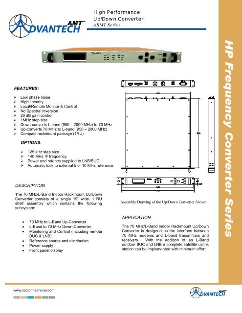
DESCRIPTION<br />
The 70 MHz/L-Band Indoor Rackmount Up/Down<br />
Converter consists of a single 19” wide, 1 RU<br />
shelf assembly which contains the following<br />
subsystem:<br />
• 70 MHz to L-Band Up-Converter<br />
• L-Band to 70 MHz Down-Converter<br />
• Monitoring and Control (including remote<br />
BUC & LNB)<br />
• Reference source and distribution<br />
• Power supply<br />
• Front panel display<br />
Assembly Drawing of the Up/Down Converter Shown<br />
APPLICATION<br />
The 70 MHz/L-Band Indoor Rackmount Up/Down<br />
Converter is designed as the interface between<br />
70 MHz modems and L-band transmitters and<br />
receivers. With the addition of an L-Band<br />
outdoor BUC and LNB a complete satellite uplink<br />
station can be implemented with minimum effort.<br />
www.satcom-servicescom
High Performance<br />
Up/Down Converter<br />
<strong>ARMT</strong> <strong>Series</strong><br />
Up-Converter<br />
Down-Converter<br />
IF input<br />
<strong>Frequency</strong> <strong>Range</strong><br />
Input Power<br />
Impedance<br />
Return Loss<br />
<strong>Frequency</strong> Step Size<br />
70 ± 18 MHz or 140 ± 36 MHz<br />
-30 dBm to -5 dBm<br />
50 Ω<br />
16 dB<br />
1 MHz, 125 kHz optional<br />
RF input<br />
<strong>Frequency</strong> range<br />
Input Power<br />
Impedance<br />
Return loss<br />
<strong>Frequency</strong> Step Size<br />
<strong>950</strong> – 2000 MHz<br />
-60 dBm to -30 dBm<br />
50 Ω<br />
16 dB<br />
1 MHz, 125 kHz optional<br />
RF output<br />
<strong>Frequency</strong> <strong>Range</strong> <strong>950</strong> – 2000 MHz<br />
Output Power (P1dB) +5 dBm<br />
Third Order Intercept +15 dBm<br />
Impedance<br />
50 Ω<br />
Return Loss<br />
16 dB<br />
Spurious (in 36 MHz band) -55 dBc<br />
Transfer Characteristics<br />
Conversion Gain<br />
10 dB @ max gain setting<br />
Gain Adjustment <strong>Range</strong> 20 dB (-10 dB to + 20 dB)<br />
Attenuator Step Size 0.1 dB<br />
Noise Figure<br />
20 dB @ max gain setting<br />
Freq. Response Flatness 70 ± 18 MHz: 1.0 dB p-p<br />
140 ± 36 MHz: 1.5 dB p-p<br />
Phase Noise<br />
-42 @ 10Hz<br />
-72 @ 100 Hz<br />
-82 @ 1 kHz<br />
-92 @ 10 kHz<br />
-102 @ 100 kHz<br />
-112 @ 1 MHz<br />
-118 @ 10 MHz<br />
-118 @ 100 MHz<br />
Reference<br />
<strong>Frequency</strong> Stability<br />
Aging<br />
Environmental<br />
Operational<br />
Gain vs. Temp. Variation<br />
Storage<br />
Humidity<br />
Altitude<br />
+/-1 x 10 -8 / day<br />
+/-3 x 10 -7 / year<br />
0°C to +50°C standard<br />
1 dB p-p for Up-converter<br />
0.75 dB/15 o C for Down-converter<br />
-55°C to +85°C<br />
Non-condensing<br />
3,000m AMSL<br />
Power Supply<br />
Voltage<br />
90 – 264 VAC (47 – 63 Hz)<br />
Power<br />
45W (typical)<br />
Output Level @ mute -65 dBm max.<br />
Power Available @ +24 VDC@ 3.5A<br />
L-band Connectors +48VDC @ 2.2 A for BUC<br />
+20VDC @ 400mA for LNB<br />
IF output<br />
<strong>Frequency</strong> range<br />
70 ± 18 MHz or 140 ± 36 MHz<br />
Output power (P1dB) 0 dBm<br />
Third order intercept +10 dBm<br />
Impedance<br />
50 Ω<br />
Return loss<br />
16 dB<br />
Spurious (in 36 MHz band) -55 dBc<br />
Transfer Characteristics<br />
Conversion Gain<br />
20 dB @ max gain setting<br />
Gain Adjustment <strong>Range</strong> 20 dB<br />
Attenuator Step Size 0.1 dB<br />
Noise Figure<br />
20 dB @ 0 dB attenuation<br />
Freq. Response Flatness 70 ± 18 MHz: 1.0 dB p-p<br />
140 ± 36 MHz: 1.5 dB p-p<br />
Phase Noise<br />
-38 @ 10Hz<br />
-68 @ 100 Hz<br />
-78 @ 1 kHz<br />
-88 @ 10 kHz<br />
-98 @ 100 kHz<br />
-108 @ 1 MHz<br />
-118 @ 10 MHz<br />
-118 @ 100 MHz<br />
Mechanical<br />
Dimensions Width 19” (482.6 mm)<br />
Height 1U 1.75” (44.45 mm)<br />
Depth 20” (508 mm)<br />
Weight<br />
6 kg (13.2 lbs)<br />
Interfaces<br />
70 MHz Input BNC female<br />
L-Band Output<br />
Type-N female<br />
L-Band Input<br />
Type-N female<br />
70 MHz Output BNC female<br />
Serial Port<br />
D-sub9 (RS485)<br />
Serial to PC<br />
D-sub9 (RS232)<br />
Serial BUC Control D-sub9 (RS485)<br />
Alarm Contacts<br />
Form C<br />
Alarm and Mute D-sub9<br />
Power<br />
IEC 60320 10 amp<br />
PB-RC510-01 Rev.01 issued 05/18/2007<br />
Specifications are subject to change without notice<br />
An ISO9001: 2000 Company<br />
United States<br />
1SATCOM SERVICES<br />
T25 Creek Lane<br />
UOak View, CA. 93510 USA<br />
Tel.: (805) 649-1384<br />
Fax: (805) 500-4328<br />
Email: Mike@satcom-services.com