Whirlybird Wind Turbine User Manual - Super Science Fair Projects
Whirlybird Wind Turbine User Manual - Super Science Fair Projects
Whirlybird Wind Turbine User Manual - Super Science Fair Projects

You also want an ePaper? Increase the reach of your titles
YUMPU automatically turns print PDFs into web optimized ePapers that Google loves.
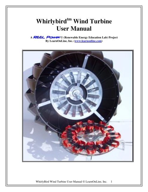
<strong>Whirlybird</strong> tm <strong>Wind</strong> <strong>Turbine</strong><br />
<strong>User</strong> <strong>Manual</strong><br />
A REEL Power © (Renewable Energy Education Lab) Project<br />
By LearnOnLine, Inc. (www.learnonline.com)<br />
WhirlyBird <strong>Wind</strong> <strong>Turbine</strong> <strong>User</strong> <strong>Manual</strong> © LearnOnLine, Inc. 1
Contents<br />
1. Overview<br />
2. Intended Use<br />
3. General Safety Precautions<br />
4. Related Issues<br />
5. Assembling the <strong>Wind</strong> <strong>Turbine</strong><br />
6. Attaching to the 3-Phase Bar Graph Board<br />
<strong>Wind</strong> <strong>Turbine</strong> Design and <strong>User</strong> <strong>Manual</strong> by…<br />
LearnOnLine, Inc. – creator, sponsor and host of the REEL Power © Project<br />
567 W. Channel Islands Blvd. #101<br />
Port Hueneme, CA 93041<br />
e-mail information@learnonline.com<br />
website www.learnonline.com<br />
Caution<br />
This kit contains powerful magnets.<br />
People with pacemakers should not<br />
handle or go near strong magnets.<br />
WhirlyBird <strong>Wind</strong> <strong>Turbine</strong> <strong>User</strong> <strong>Manual</strong> © LearnOnLine, Inc. 2
1. Overview<br />
Imagine creating a 3-phase wind turbine from<br />
a common, everyday roof ventilator along<br />
with some magnets and coils of wire. That’s<br />
what we’ve created for your study of wind<br />
technology.<br />
We chose the <strong>Whirlybird</strong> tm<br />
several reasons.<br />
roof ventilator for<br />
First, it has great bearings that simply will not<br />
wear out under normal – and even severe –<br />
use. Without great bearings your wind<br />
turbine is always fighting friction that only<br />
serves to slow it down with the attendant loss<br />
of power.<br />
Second, it can be easily constructed<br />
with common tools and without<br />
soldering or drilling.<br />
Third, it can be used indoors and<br />
[especially] outdoors where your<br />
study of day-to-day and season-byseason<br />
wind never stops.<br />
Fourth, it produces 3-phase power<br />
just like the commercial wind<br />
turbines, which allows you to study<br />
this marvelous electrical principle first<br />
hand by using your computer and our<br />
3-phase Bar Graph Board.<br />
And, fifth, you will be able to modify it in order to study the effects of magnetism<br />
and how you can optimize the mechanical components to produce maximum power.<br />
Here is what is included in the <strong>Whirlybird</strong> tm <strong>Wind</strong> <strong>Turbine</strong> Kit:<br />
12 Wire Coils<br />
16 Bar magnets<br />
1 6-position terminal block<br />
1 8” diameter round metal rotor disk<br />
1 8” diameter round Plexiglas stator disk<br />
1 5/16”, 7/8” long threaded rod extender<br />
1 5/16”, 1 ½” long bolt<br />
10 5/16” flat washers<br />
3 1” flat washers<br />
Lomanco <strong>Whirlybird</strong> tm model B1B-12 roof ventilator purchased separately at Home<br />
Depot and other home improvement outlets.<br />
WhirlyBird <strong>Wind</strong> <strong>Turbine</strong> <strong>User</strong> <strong>Manual</strong> © LearnOnLine, Inc. 3
2. Intended Use<br />
The hardware, software and experiments are developed exclusively for educational<br />
teaching and demonstration purposes. Any other use such as in life-critical applications is<br />
prohibited!<br />
3. Safety Precautions<br />
In order to avoid any risks, you must abide by the following Safety Precautions when<br />
working with the <strong>Whirlybird</strong> tm <strong>Wind</strong> <strong>Turbine</strong>.<br />
• The system may only be set up and operated by a competent person. Younger<br />
students require adult supervision at all times.<br />
• Read the assembly instructions and experiments before executing them.<br />
• The <strong>Whirlybird</strong> tm <strong>Wind</strong> <strong>Turbine</strong> is not a toy. Assemble and operate it<br />
responsibly. The use of safety glasses and protective gloves while assembling<br />
the wind turbine and performing experiments is highly recommended<br />
• READ AND UNDERSTAND EACH ASSEMBLY PROCEDURE BEFORE<br />
EXECUTING IT. This will help to understand what is to be done and, also,<br />
prevent inadvertent mistakes that could lead to incorrect results or possible injury.<br />
• LearnOnLine, its distributors or affiliates will not accept responsibility for injuries<br />
or damage sustained in the event that these Safety Precautions not followed<br />
completely.<br />
Caution<br />
This kit contains powerful magnets.<br />
People with pacemakers should not<br />
handle or go near strong magnets.<br />
WhirlyBird <strong>Wind</strong> <strong>Turbine</strong> <strong>User</strong> <strong>Manual</strong> © LearnOnLine, Inc. 4
4. Related Issues<br />
4.1 Reverse Engineering<br />
You are not entitled to reverse engineer, decompile or disassemble the software product<br />
in whole or in part.<br />
4.2 Errors and Omissions<br />
LearnOnLine has made every effort to supply the software and hardware without errors;<br />
however, we are not responsible for any unintentional errors or omissions in the design,<br />
construction or operation of the product. If you should notice undiscovered errors, please<br />
contact us.<br />
LearnOnLine, Inc.<br />
information@learnonline.com<br />
4.3 System Requirements<br />
<strong>Wind</strong>ows Pentium class computer with USB interface port. MACs with INTEL<br />
processors can use Parallels “Desktop 3.0 for Mac”.<br />
4.4 Software Installation<br />
You will need administrator rights for software installation under <strong>Wind</strong>ows 2000,<br />
<strong>Wind</strong>ows XP or <strong>Wind</strong>ows Vista.<br />
4.5 Warranty<br />
LearnOnLine, Inc. warrants its products against defects in materials and workmanship for<br />
a period of 90 days. If you discover a defect, LearnOnLine will, at its option, repair,<br />
replace or refund the purchase price. Simply contact us at information@learnonline.com.<br />
4.6 Disclaimer of Liability<br />
LearnOnLine, Inc. is not responsible for special, incidental or consequential damages<br />
resulting from any breach of warranty, or under any legal theory, including lost profits,<br />
downtime, goodwill, damage to or replacement of equipment or property, and any costs<br />
for recovering or reproducing any data stored in or used with LearnOnLine products.<br />
LearnOnLine is also not responsible for any personal damage, including that to life and<br />
health, resulting from use of any of our products. You take full responsibility for using<br />
LearnOnLine products and experiments no matter how life threatening it may be.<br />
WhirlyBird <strong>Wind</strong> <strong>Turbine</strong> <strong>User</strong> <strong>Manual</strong> © LearnOnLine, Inc. 5
5. Assembling the <strong>Wind</strong> <strong>Turbine</strong><br />
You are about to begin a worthwhile and engaging project by creating a 3-phase wind<br />
turbine from a common, everyday roof ventilator, some magnets and coils of wire.<br />
Before starting first check to see that you have the following component parts that came<br />
with your kit to begin assembly:<br />
1 Lomanco <strong>Whirlybird</strong> tm roof ventilator (purchased separately)<br />
12 Wire Coils<br />
16 Bar magnets<br />
1 6-position terminal block<br />
2 8” diameter round metal rotor disk<br />
2 8” diameter round Plexiglas stator disk<br />
1 5/16”, 7/8” long threaded rod coupler<br />
2 5/16”, 1 ½” long bolt<br />
3 1” flat washers<br />
10 5/16” flat washers<br />
You will also need the following tools and materials to complete the assembly:<br />
• Flat head screwdriver<br />
Crescent wrench<br />
• Grease marking pen<br />
Multimeter<br />
• Pocket or Exacto tm knife<br />
2-part Epoxy Glue + stirring stick<br />
• Latex gloves & Safety Glasses Electrical tape<br />
• Length of 6-conductor wire (length to be determined by your setup)<br />
The <strong>Whirlybird</strong> tm <strong>Wind</strong> <strong>Turbine</strong> is designed to work with the 3-Phase Bar Graph<br />
Board. You are not required to have this board; however, the experiments towards the<br />
end of this <strong>User</strong> <strong>Manual</strong> use the 3-Phase Bar Graph Board along with your computer<br />
for graphic display.<br />
WhirlyBird <strong>Wind</strong> <strong>Turbine</strong> <strong>User</strong> <strong>Manual</strong> © LearnOnLine, Inc. 6
Part 1 – Preparing the <strong>Wind</strong> <strong>Turbine</strong> for Assembly<br />
1.1 The core part of the wind turbine assembly is the <strong>Whirlybird</strong> 12” diameter roof<br />
ventilator manufactured by Lomanco (part number B1B-12). You can find it in most<br />
Home Depots or other hardware stores in the roofing section. It looks like this all<br />
packaged up in its box (left). Carefully remove the staples, open the top and this is<br />
what you will see inside (right).<br />
1.2 Remove the wind turbine from the box and turn it over (left). You will see that<br />
the 3-leg triangular base is attached to the fan assembly by a single nut. Remove the<br />
nut and washer and save them for later use (right).<br />
WhirlyBird <strong>Wind</strong> <strong>Turbine</strong> <strong>User</strong> <strong>Manual</strong> © LearnOnLine, Inc. 7
1.3 Next, remove the 3-leg base assembly by holding onto the fan struts with one<br />
hand and carefully wiggling off the leg assembly (left) with the other. Then screw on<br />
the 7/8” threaded rod coupler to the fan’s shaft (right). Finger tight is fine.<br />
1.4 With the 3-leg base sitting upright (below) place a 1” flat washer on each of the<br />
three rivets on the top triangular section. Mix a small portion of epoxy glue and dab<br />
the glue into the middle of each washer to hold the washer to the aluminum section.<br />
Use a plastic knife or a Popsicle stick to mix and dab the epoxy. BE VERY<br />
CAREFUL NOT TO INHALE THE FUMES AND, ALSO, WEAR<br />
PROTECTIVE GLOVES AND SAFTEY GLASSES. Allow the glue to dry for<br />
about 10 to 15 minutes.<br />
WhirlyBird <strong>Wind</strong> <strong>Turbine</strong> <strong>User</strong> <strong>Manual</strong> © LearnOnLine, Inc. 8
Part 2 – Assembling the Magnet Rotor<br />
Caution<br />
This kit contains powerful magnets.<br />
People with pacemakers should not<br />
handle or go near strong magnets.<br />
2.1 Starting with the 16 bar magnets, use a grease pen to mark each magnet’s side<br />
with an “N” and the opposite side with an “S” for North and South. It’s not important<br />
to know which side is actually North or South, only that they are marked as opposites.<br />
If you really want to know North from South, use a compass needle to indicate which<br />
is which. Do this with the remainder of the magnets. Be careful not to allow the<br />
magnets to crimp your fingers…they are very powerful!! Also, wear safety<br />
glasses since the magnets may shatter and fling sharp particles into your eyes.<br />
The magnets should look like this when finished (right).<br />
2.2 Next, place the 16 magnets around the edge of the 8” metal disk with the large<br />
hole in the middle. Make sure to alternate the magnets N-S-N-S…. as shown below.<br />
This is VERY IMPORTANT, which is why you marked them North and South in the<br />
first place. This may take some time since the magnets will want to snap together.<br />
Once in place, epoxy the each magnet to the metal disk by lifting up on the magnet<br />
and dabbing a bead of epoxy to the top and bottom ends. Use a plastic knife or a<br />
Popsicle stick to mix and to dab the epoxy. BE VERY CAREFUL NOT TO<br />
INHALE THE FUMES AND, ALSO, WEAR PROTECTIVE GLOVES AND<br />
SAFETY GLASSES. This epoxy sets very quickly so make sure you have the<br />
magnets correctly arranged before you start.<br />
WhirlyBird <strong>Wind</strong> <strong>Turbine</strong> <strong>User</strong> <strong>Manual</strong> © LearnOnLine, Inc. 9
2.3 After the epoxy has had a chance to<br />
set, temporally place the magnet disk on the<br />
fan struts of the wind turbine. Holding the<br />
center shaft in one hand, carefully give the<br />
turbine fan a gentle spin to see if the rotor<br />
disk is centered on the shaft. Adjust the<br />
rotor disk until it is properly centered. With<br />
a grease pen mark the struts to indicate the<br />
disk’s outer edge. You can now epoxy the<br />
disk to the struts by placing a dab of epoxy<br />
both on each strut and the corresponding<br />
back of the metal disk. Before the epoxy has<br />
a chance to set, again make sure that the disk<br />
is centered. BE VERY CAREFUL NOT<br />
TO INHALE THE FUMES AND, ALSO,<br />
WEAR PROTECTIVE GLOVES AND SAFETY GLASSES.<br />
WhirlyBird <strong>Wind</strong> <strong>Turbine</strong> <strong>User</strong> <strong>Manual</strong> © LearnOnLine, Inc. 10
Part 3 – Assembling the Coil Stator<br />
3.1 There are twelve coils that form the 3-phase<br />
electrical coil assembly. With a pocket or Exacto tm<br />
knife carefully strip away about ½ inch of the<br />
enamel coating from both ends of each coil. Make<br />
sure all the enamel has been stripped away. Be<br />
careful not to cut your fingers in the process.<br />
3.2 You will need to add more length to the coil<br />
ends so “gently” pull one wire at a time towards you to find where it starts. Then pull<br />
the wire out from the electrical tape to make it longer.<br />
3.3 Strip the paper from the 8” Plexiglas disk.<br />
3.4 Place four coils around<br />
the disk in the 12, 3, 6 and 9<br />
o’clock positions as shown.<br />
Make sure that the coil wire<br />
ends face the outside of the<br />
plastic disk.<br />
Put a dab of epoxy on the<br />
bottoms of each coil and<br />
adhere it to the plastic disk.<br />
This will form Phase 1 of the<br />
three coil phases.<br />
3.5 Twist tie<br />
three of the coil<br />
wire ends<br />
together going<br />
from the left wire<br />
of one coil to the<br />
right wire of the<br />
next coil. There<br />
should be two<br />
free wires<br />
remaining from<br />
two of the coils.<br />
The free ends in<br />
the photo are on<br />
the coils in the 3<br />
and 6 o’clock<br />
positions.<br />
WhirlyBird <strong>Wind</strong> <strong>Turbine</strong> <strong>User</strong> <strong>Manual</strong> © LearnOnLine, Inc. 11
3.6 Turn the plastic disk<br />
over and fold over the<br />
twisted wire ends to the<br />
underside of the disk. Apply<br />
a piece of electrical tape to<br />
hold them to the disk.<br />
3.7 Place a dab of epoxy<br />
glue on the end of the 6<br />
position barrier strip and<br />
glue it to the underside of the<br />
disk as shown.<br />
3.8 With a grease pen label<br />
the screws as 1 through 6 as<br />
shown.<br />
3.9 Attach the left-most<br />
free wire to screw #1 and the<br />
right-most free wire to screw<br />
#2 and screw them in place.<br />
Make sure that these wires are attached to the screws nearest the outer edge of the<br />
disk, as the equivalent inner screws will eventually attach to a cable leading to the 3-<br />
Phase Bar Graph Board.<br />
The wire attachments should<br />
look like this on the screw<br />
terminals.<br />
WhirlyBird <strong>Wind</strong> <strong>Turbine</strong> <strong>User</strong> <strong>Manual</strong> © LearnOnLine, Inc. 12
3.10 Repeat the<br />
procedure for the<br />
next four coils.<br />
3.11 Attach the<br />
left-most free wire<br />
to screw terminal #3<br />
and the right-most<br />
free wire to screw<br />
terminal #4.<br />
WhirlyBird <strong>Wind</strong> <strong>Turbine</strong> <strong>User</strong> <strong>Manual</strong> © LearnOnLine, Inc. 13
3.12 Repeat the<br />
procedure for the<br />
last four coils.<br />
3.13 Attach the<br />
left-most free wire<br />
to screw terminal<br />
#5 and the rightmost<br />
free wire to<br />
screw terminal #6.<br />
Tip<br />
If the coils get<br />
crowded<br />
together, squeeze<br />
the inner part of<br />
the coils so that<br />
they fit better<br />
side by side.<br />
WhirlyBird <strong>Wind</strong> <strong>Turbine</strong> <strong>User</strong> <strong>Manual</strong> © LearnOnLine, Inc. 14
3.14 Before going further it’s time to test the coil<br />
connections with a multimeter. Set the multimeter<br />
dial to resistance (sometimes indicated by the ohm<br />
symbol). Next, apply the probes to screw terminals<br />
#1 and #2. If all is correct, the reading should be<br />
between 25 and 30 ohms. This is the total resistance<br />
of the first four coils taken together (in series). If<br />
your reading is well above this value, you probably<br />
have an “open circuit” and need to re-check the coil<br />
connections as they most likely are not stripped of<br />
enable and are not making contact. Re strip the wires<br />
and re twist them together again. Then check the<br />
other two coil arrangements between screw terminals<br />
#3 and #4 as well as #5 and #6. Repeat the repair<br />
procedure if the coil resistance is not within limits.<br />
3.15 Add another dab<br />
of epoxy to the three 1”<br />
washers on the<br />
triangular leg assembly<br />
and “CAREFULLY”<br />
place the Plexiglas disk<br />
on top of the screws<br />
with the black terminal<br />
block on the underside<br />
of the disk facing down.<br />
Make sure that the hole<br />
in the disk is centered<br />
on the hole in the<br />
triangular leg assembly.<br />
THIS IS VERY<br />
IMPROTANT!!<br />
Keep the disk<br />
centered on the hole in<br />
the triangular<br />
assembly.<br />
WhirlyBird <strong>Wind</strong> <strong>Turbine</strong> <strong>User</strong> <strong>Manual</strong> © LearnOnLine, Inc. 15
Part 4– Putting It All Together<br />
Before putting the stator and rotor assemblies together take some time to examine the<br />
stator coils. They should be flat with no wires sticking up. One way to ensure this is to<br />
put a large telephone book on top of the coils to squash them down. If you take the time<br />
to do this and let it sit overnight, it will bring you a better working wind turbine. Even if<br />
you don’t flatten the coils now, you can take the wind turbine apart to do this at a later<br />
time. So, let’s get going on putting it all together….<br />
4.1 To finalize the<br />
connection between the<br />
rotor and stator assemblies,<br />
insert the 1.5”, 15/16” bolt<br />
through the bottom of the<br />
stator assembly with 1 or 2<br />
flat washers near the head<br />
of the bolt. Push the bolt<br />
through the center hole in<br />
the triangular base<br />
assembly then add about 4<br />
or 5 flat washers capped<br />
off with the nut that you<br />
saved from step 1.2. If<br />
you don’t have the nut<br />
anymore simply add a few more washers to the bolt. The nut just makes it easier to<br />
handle. Regardless, make sure that the free end of the bolt has about 1/2” of thread<br />
exposed.<br />
4.2 Now insert the<br />
triangular base through<br />
the threaded rod coupler,<br />
which is connected to the<br />
fan assembly. Screw the<br />
two assemblies together<br />
by rotating the threaded<br />
rod coupler in a counterclockwise<br />
direction with<br />
your thumb. Gently<br />
wiggle the triangular base<br />
assembly to make sure<br />
that the coils are not<br />
scraping the magnets. If<br />
they are, disassemble the<br />
two parts and flatten out the coils with a phone book as weight or add another washer.<br />
WhirlyBird <strong>Wind</strong> <strong>Turbine</strong> <strong>User</strong> <strong>Manual</strong> © LearnOnLine, Inc. 16
Part 5 – First Tests<br />
5.1 Before doing anything else, place the turbine base on a flat surface and give the<br />
turbine fan a GENTLE spin. If you hear any scraping noise this means that the coil<br />
wires are scraping against the magnets. Unbolt the base and fan assembly by<br />
unscrewing the threaded rod coupler and add another washer to the 1.5” 15/16” bolt.<br />
This should correct the problem. If it doesn’t, add yet another washer. Remember,<br />
however, that each additional washer will increase the space between the coils and<br />
magnets, thus producing less magnetic coupling and less voltage and current output.<br />
The whole idea is to reduce the gap between the coils and magnets to a minimum.<br />
Therefore, disassemble the two parts and check to see how best to reduce this gap.<br />
Now to see how well the wind turbine generates voltage.<br />
5.2 With the multimeter set to AC<br />
voltage on a range between 0 and 5<br />
volts place the meter probes on screw<br />
terminals #1 and #2 then give the<br />
turbine a good spin. You should<br />
experience a voltage reading between<br />
1 and 4 volts AC depending on how<br />
fast you spin the turbine. Repeat the<br />
test for screw terminals 3 & 4 and 5 &<br />
6. If you get the same general voltage<br />
reading on all three screw terminal<br />
pairs this indicates that the turbine is<br />
working correctly.<br />
WhirlyBird <strong>Wind</strong> <strong>Turbine</strong> <strong>User</strong> <strong>Manual</strong> © LearnOnLine, Inc. 17
5.3 It’s now time to hookup a multi-wire cable to the terminal block. You will need<br />
to get a length of 6 conductor stranded or solid wire for this next step. It should be<br />
long enough to reach from where you will eventually place the wind turbine to where<br />
your computer is located. You can go to Home Depot and get a length of any size<br />
CAT-5 cable, which is normally used for Ethernet cables. It comes as 8 conductor<br />
solid wire, so there are two extra wires in the cable. Or if you search around you can<br />
find 6 conductor cables at Home Depot or at distributors like Digikey, Mouser or<br />
Jameco. Whatever you do, don’t pay extra for expensive cables – this project does<br />
not require them. Hookup the cable as in the photo below and make sure to note<br />
which colors are connected to which screw terminals. Then use a tie wrap to secure<br />
the cable to one of the aluminum struts to relieve any strain on the connection to the<br />
screw terminals.<br />
Congratulations!!!<br />
If the voltage tests worked you have successfully completed the wind turbine assembly<br />
portion of the project. However if you’re still experiencing problems, review the<br />
previous steps to see if you have done all the things correctly. Sometimes haste makes<br />
for mistakes.<br />
WhirlyBird <strong>Wind</strong> <strong>Turbine</strong> <strong>User</strong> <strong>Manual</strong> © LearnOnLine, Inc. 18
Part 6 - Attaching to the 3-phase Bar Graph Board<br />
6.1 Attach the<br />
wire cable from the<br />
<strong>Whirlybird</strong> tm <strong>Wind</strong><br />
<strong>Turbine</strong>’s 6-screw<br />
terminal block to<br />
the equivalent pin<br />
numbers on the 3-<br />
Phase Bar Graph<br />
Board. These<br />
numbers are<br />
clearly marked on<br />
the side of the<br />
board. Simply<br />
strip the wire cable<br />
ends, push down<br />
on the springloaded<br />
terminals<br />
and insert the<br />
wires. Gently pull<br />
on each one to<br />
make sure that a<br />
good connection is<br />
made.<br />
P1 P2 P3 DC<br />
3-Phase Bar Graph Board<br />
Battery<br />
X2<br />
X1<br />
Power<br />
USB<br />
USB<br />
LOAD<br />
1<br />
2<br />
3<br />
4<br />
5<br />
6<br />
1 2 3 4 5 6<br />
6.2 If you are at your computer attach the USB cable between the 3-Phase Bar Graph Board<br />
and the computer’s USB port. If you’re not at the computer, insert a fresh 9-volt battery into the<br />
3-Phase Bar Graph Board. Set the toggle switch on the bottom-center of bhe board to the left<br />
for battery operation and to the right for USB operation. In either case you should see the four bar<br />
graph LEDs illuminate simultaneously three times; this is a test to make sure that all the LEDs are<br />
working.<br />
6.3 Set the Voltage Scale switch to the X1 position (down). The Voltage Scale switch is to the<br />
right of the USB connector. This means that each LED represents 1 volt. Setting the switch to<br />
the X2 postion simply doubles the voltage of each LED from 1 volt to 2 volts. You can change the<br />
X1 – X2 setting at anytime.<br />
6.4 Now give the turbine a spin. The Phase 1, Phase 2 and Phase 3 LED bar graphs should<br />
illuminate in order with Phase 1 then Phase 2 then Phase 3. The fourth vertical set of LEDs<br />
indicate the DC voltage being generated. If you don’t see this happening, go back and recheck<br />
the wire hookup between the wind turbine and the 3-Phase Bar Graph Board. It’s probably a<br />
loose wire or one that is not stripped of insulation that’s causing the problem.<br />
If you have come this far please refer to the 3-Phase Bar Graph <strong>User</strong> <strong>Manual</strong> for detailed<br />
installation and operating insturctions plus interesting computer experiments.<br />
WhirlyBird <strong>Wind</strong> <strong>Turbine</strong> <strong>User</strong> <strong>Manual</strong> © LearnOnLine, Inc. 19