Graphene/Polymer Nanocomposites - Tarleton State University
Graphene/Polymer Nanocomposites - Tarleton State University
Graphene/Polymer Nanocomposites - Tarleton State University

You also want an ePaper? Increase the reach of your titles
YUMPU automatically turns print PDFs into web optimized ePapers that Google loves.
Macromolecules 2010, 43, 6515–6530 6515<br />
DOI: 10.1021/ma100572e<br />
<strong>Graphene</strong>/<strong>Polymer</strong> <strong>Nanocomposites</strong><br />
Hyunwoo Kim, † Ahmed A. Abdala, ‡ and Christopher W. Macosko* ,†<br />
† Department of Chemical Engineering and Materials Science, <strong>University</strong> of Minnesota, Minneapolis,<br />
Minnesota 55455-0331, and ‡ Chemical Engineering Program, The Petroleum Institute, Abu Dhabi,<br />
United Arab Emirates<br />
Received March 15, 2010; Revised Manuscript Received June 14, 2010<br />
ABSTRACT: <strong>Graphene</strong> has emerged as a subject of enormous scientific interest due to its exceptional<br />
electron transport, mechanical properties, and high surface area. When incorporated appropriately, these<br />
atomically thin carbon sheets can significantly improve physical properties of host polymers at extremely<br />
small loading. We first review production routes to exfoliated graphite with an emphasis on top-down<br />
strategies starting from graphite oxide, including advantages and disadvantages of each method. Then<br />
solvent- and melt-based strategies to disperse chemically or thermally reduced graphene oxide in polymers are<br />
discussed. Analytical techniques for characterizing particle dimensions, surface characteristics, and dispersion<br />
in matrix polymers are also introduced. We summarize electrical, thermal, mechanical, and gas barrier<br />
properties of the graphene/polymer nanocomposites. We conclude this review listing current challenges<br />
associated with processing and scalability of graphene composites and future perspectives for this new class of<br />
nanocomposites.<br />
1. Introduction<br />
<strong>Polymer</strong> nanocomposites based on carbon black, carbon<br />
nanotubes, and layered silicates have been used for improved<br />
mechanical, thermal, electrical, and gas barrier properties of<br />
polymers. 1-3 The discovery of graphene with its combination of<br />
extraordinary physical properties and ability to be dispersed in<br />
various polymer matrices has created a new class of polymer<br />
nanocomposites.<br />
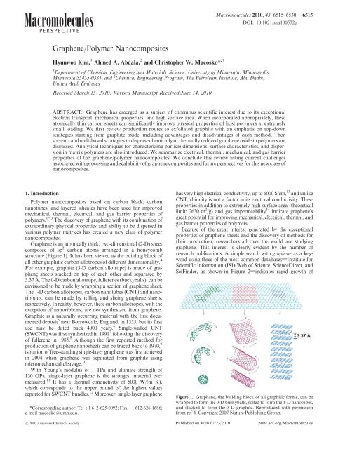
<strong>Graphene</strong> is an atomically thick, two-dimensional (2-D) sheet<br />
composed of sp 2 carbon atoms arranged in a honeycomb<br />
structure (Figure 1). It has been viewed as the building block of<br />
all other graphitic carbon allotropes of different dimensionality. 4<br />
For example, graphite (3-D carbon allotrope) is made of graphene<br />
sheets stacked on top of each other and separated by<br />
3.37 A˚. The 0-D carbon allotrope, fullerenes (buckyballs), can be<br />
envisioned to be made by wrapping a section of graphene sheet.<br />
The 1-D carbon allotropes, carbon nanotubes (CNT) and nanoribbons,<br />
can be made by rolling and slicing graphene sheets,<br />
respectively. In reality, however, these carbon allotropes, with the<br />
exception of nanoribbons, are not synthesized from graphene.<br />
Graphite is a naturally occurring material with the first documented<br />
deposit 5 near Borrowdale, England, in 1555, but its first<br />
use may be dated back 4000 years. 6 Single-walled CNT<br />
(SWCNT) was first synthesized in 1991 7 following the discovery<br />
of fullerene in 1985. 8 Although the first reported method for<br />
production of graphene nanosheets can be traced back to 1970, 9<br />
isolation of free-standing single-layer graphene was first achieved<br />
in 2004 when graphene was separated from graphite using<br />
micromechanical cleavage. 10<br />
With Young’s modulus of 1 TPa and ultimate strength of<br />
130 GPa, single-layer graphene is the strongest material ever<br />
measured. 11 It has a thermal conductivity of 5000 W/(m 3 K),<br />
which corresponds to the upper bound of the highest values<br />
reported for SWCNT bundles. 12 Moreover, single-layer graphene<br />
*Corresponding author: Tel þ1 612-625-0092; Fax þ1 612-626-1686;<br />
e-mail macosko@umn.edu.<br />
has very high electrical conductivity, up to 6000 S/cm, 13 and unlike<br />
CNT, chirality is not a factor in its electrical conductivity. These<br />
properties in addition to extremely high surface area (theoretical<br />
limit: 2630 m 2 /g) and gas impermeability 14 indicate graphene’s<br />
great potential for improving mechanical, electrical, thermal, and<br />
gas barrier properties of polymers.<br />
Because of the great interest generated by the exceptional<br />
properties of graphene sheets and the discovery of methods for<br />
their production, researchers all over the world are studying<br />
graphene. This interest is clearly evident by the number of<br />
research publications. A simple search with graphene as a keyword<br />
using three of the most common databases;Institute for<br />
Scientific Information (ISI)-Web of Science, ScienceDirect, and<br />
SciFinder, as shown in Figure 2;indicates rapid growth of<br />
Figure 1. <strong>Graphene</strong>, the building block of all graphitic forms, can be<br />
wrapped to form the 0-D buckyballs, rolled to form the 1-D nanotubes,<br />
and stacked to form the 3-D graphite. Reproduced with permission<br />
from ref 4. Copyright 2007 Nature Publishing Group.<br />
r 2010 American Chemical Society<br />
Published on Web 07/23/2010<br />
pubs.acs.org/Macromolecules
6516 Macromolecules, Vol. 43, No. 16, 2010 Kim et al.<br />
publications post 2005 with nearly 3000 publications in 2009.<br />
A similar trend in number of publications is also observed using<br />
graphene composites as a keyword.<br />
In this paper, we review this literature with a focus on<br />
graphene/polymer composites. We first review the different<br />
methods for preparation of graphene sheets with an emphasis<br />
on methods suitable for polymer composite applications. Then<br />
methods to characterize graphene including number of layers,<br />
sheet size, and chemical modification are discussed. Dispersion<br />
routes for graphene into polymers and the resultant polymer/<br />
graphene composite properties are also reviewed. We conclude<br />
Hyunwoo Kim received his B.S. degree in chemical engineering<br />
from Seoul National <strong>University</strong>. After completing Ph.D.<br />
in chemical engineering with Professor Christopher W.<br />
Macosko at the <strong>University</strong> of Minnesota, he continued his<br />
research at Minnesota on processing, structure, and properties<br />
of graphene/polymer nanocomposites as a postdoctoral<br />
fellow. He will soon join the Dow Chemical Company as a<br />
Materials Processing Engineer.<br />
with challenges for future growth of this exciting new class of<br />
nanocomposites.<br />
2. Bottom-Up <strong>Graphene</strong><br />
In bottom-up processes, graphene is synthesized by a variety<br />
of methods such as chemical vapor deposition (CVD), 15-21 arc<br />
discharge, 22,23 epitaxial growth on SiC, 24-30 chemical conversion, 31-33<br />
reduction of CO, 34 unzipping carbon nanotubes, 35-37 and selfassembly<br />
of surfactants. 38 CVD and epitaxial growth often produce<br />
tiny amounts of large-size, defect-free graphene sheets. They<br />
may be more attractive than the mechanical cleavage method 10 for<br />
production of graphene sheets for fundamental studies and<br />
electronic applications but are not a suitable source for polymer<br />
nanocomposites that require a large amount of graphene sheets<br />
preferably with modified surface structure. The nature, average<br />
size, and thickness of the graphene sheets produced by different<br />
bottom-up methods as well as the advantages and disadvantages of<br />
each method are summarized in Table 1.<br />
3. Top-Down <strong>Graphene</strong><br />
In top-down processes, graphene or modified graphene sheets<br />
are produced by separation/exfoliation of graphite or graphite<br />
derivatives (such as graphite oxide (GO) and graphite fluoride 39 ).<br />
In general, these methods are suitable for large scale production<br />
required for polymer composite applications. Starting from<br />
graphite or its derivatives offers significant economic advantages<br />
over the bottom-up methods; graphite is a commodity material<br />
with current annual global production of over 1.1 million tons at<br />
$825/ton in 2008. 40 Therefore, the top-down approaches will be<br />
discussed in more detail. Figure 3 shows a block diagram which<br />
summarizes the different routes reported for production of<br />
graphene or modified graphene starting from graphite or GO.<br />
Alkali metal 41 -oracid 42,43 -intercalated graphite can be expanded<br />
upon heat treatment to produce a thicker (∼100 nm)<br />
form of 2-D carbon known as expanded graphite (EG), which is<br />
commonly used as a filler for polymer composites. However, the<br />
Ahmed A. Abdala is assistant professor at the Chemical<br />
Engineering Department, The Petroleum Institute, Abu<br />
Dhabi, UAE. Dr. Abdala obtained his Ph.D. degree in<br />
Chemical Engineering and Fibers & <strong>Polymer</strong> Sciences from<br />
North Carolina <strong>State</strong> <strong>University</strong> in 2003. He also holds an<br />
M.S. in Chemical Engineering (North Carolina <strong>State</strong> <strong>University</strong>),<br />
M.S. in Petrochemicals, and B.S. in Petroleum<br />
Refining (Suez Canal <strong>University</strong>, Egypt). He is the inventor<br />
of the method for production of thermally reduced graphene<br />
(TRG). Along with his research interests on production,<br />
functionalization, and applications of graphene, Abdala’s<br />
research focuses on rheology and applications of watersoluble<br />
polymers.<br />
Chris Macosko is Director of the Industrial Partnership for<br />
Research in Interfacial and Materials Engineering and Professor<br />
of Chemical Engineering and Materials Science at the<br />
<strong>University</strong> of Minnesota and a member of the National<br />
Academy of Engineering. He received his B.S. from Carnegie<br />
Mellon, M.Sc. from Imperial College, London, and Ph.D.<br />
from Princeton. He has advised nearly 100 M.S. and Ph.D.<br />
students with whom he has published over 400 papers in<br />
rheology and polymer processing, particularly processing<br />
with reaction such as reaction injection molding, polyurethane<br />
foam, cross-linking, and reactive compatibilization of<br />
polymer blends.
Perspective Macromolecules, Vol. 43, No. 16, 2010 6517<br />
layered structure of graphite is still maintained in EG. 44 Recently,<br />
a thinner form (∼10 nm) of EG known as graphite nanoplatelets<br />
(GNP) was produced by either thermal expansion of fluorinated<br />
graphite intercalation compounds 45 or microwave radiation of<br />
acid-intercalated graphite followed by pulverization using ball<br />
milling or ultrasonication. 46,47 Because the large diameter and<br />
rigidity of graphite flakes are preserved in this process, even<br />
without complete exfoliation, GNP can improve electrical conductivity<br />
and mechanical properties of polymers at substantially<br />
smaller loadings than graphite or EG. 47,48 Properties of<br />
GNP reinforced polymers will be mentioned for comparison in<br />
section 6, but since the focus of this review is on single- or a fewlayer<br />
graphene materials, GNP will not be discussed further.<br />
3.1. Direct Exfoliation of Graphite. Micromechanical cleavage<br />
of graphite gave birth to the interest in graphene. 10 It can<br />
produce large-size, high-quality sheets but in very limited<br />
quantities, which makes it only suitable for fundamental studies<br />
or electronic applications. 10 However, recently graphite has<br />
also been directly exfoliated to single- and multiple-layer graphene<br />
via sonication in the presence of polyvinylpyrrolidone 49<br />
or N-methylpyrrolidone, 50 electrochemical functionalization of<br />
graphite assisted with ionic liquids, 51 and through dissolution in<br />
superacids. 52 The direct sonication method has potential to be<br />
scaled up to produce large quantities of single- and multiplelayer<br />
graphene or functionalized graphene that can be used for<br />
composite applications. However, separation of the exfoliated<br />
graphene sheets from the bulk graphite could be a challenge. On<br />
the other hand, dissolution of graphite in chlorosulfonic acid 52<br />
has potential for a large scale production, but the hazardous<br />
nature of the hydrosulfonic and the cost of its removal may limit<br />
this potential. Electrochemical exfoliation methods produce<br />
graphene sheets functionalized with imidazolium groups that<br />
assist dispersion in aprotic solvents. 51<br />
3.2. Graphite Oxide (GO). Currently, the most promising<br />
methods for large scale production of graphene are based on<br />
the exfoliation and reduction of GO. GO was first prepared<br />
over 150 years ago by Brodie. 53 It is also produced using<br />
different variations of the Staudenmaier 54 or Hummers 55<br />
methods in which graphite is oxidized using strong oxidants<br />
such as KMnO 4 , KClO 3 , and NaNO 2 in the presence of nitric<br />
acid or its mixture with sulfuric acid. Analogous to graphite,<br />
which is composed of stacks of graphene sheets, GO is<br />
composed of graphene oxide sheets stacked with an interlayer<br />
spacing between 6 and 10 Å depending on the water<br />
content. 56 The structure of graphene oxide has been the<br />
subject of theoretical 57-60 and experimental studies. 61-72<br />
The Lerf-Klinowski model 66,67 is believed to be the most<br />
likely description of GO structure. The model describes GO<br />
as built of pristine aromatic “islands” separated from each<br />
other by aliphatic regions containing epoxide and hydroxyl<br />
groups and double bonds as shown in Figure 4a. Recently,<br />
Gao et al. 61 studied the structure of GO using 13 C NMR.<br />
They proposed that GO contains ketones, 6-membered<br />
lactol rings, and tertiary alcohol (Figure 4b) in addition<br />
to epoxide and hydroxyl groups. GO has an approximate<br />
C/O/H atomic ratio of 2/1/0.8. 53,73 During oxidation graphene<br />
oxide sheets undergo unzipping resulting in size reduction<br />
compared to the parent graphite flake size. 74 For more details<br />
about GO, we refer the reader to the extensive review of GO<br />
preparation, structure, and reactivity by Dreyer et al. 75<br />
Figure 2. Number of publications returned using “graphene” and<br />
“graphene composites” as keywords in ISI-Web of Science, Science-<br />
Direct, and SciFinder. Duplicates were removed.<br />
Figure 3. Top-down methods for production of graphene and modified<br />
graphene starting from graphite or via graphite oxide (GO).<br />
Table 1. Bottom-Up Processes for <strong>Graphene</strong> Production<br />
typical dimension<br />
method thickness lateral advantage disadvantage refs<br />
confined self-assembly single layer 100 0 s nm thickness control existence of defects 38<br />
CVD few layers very large (cm) large size; high quality small production scale 15-21<br />
arc discharge<br />
single-, bi-,<br />
few 100 nm to a can produce ∼10 g/h low yield of graphene; 22, 23<br />
and few layers few μm<br />
of graphene<br />
carbonaceous impurities<br />
epitaxial growth<br />
few layers up to cm size very large area of<br />
very small scale 24-30<br />
on SiC<br />
pure graphene<br />
unzipping of<br />
multiple layers few μm<br />
size controlled by<br />
expensive<br />
35-37<br />
carbon nanotubes<br />
long nanoribbons selection of the<br />
starting nanotubes<br />
starting material;<br />
oxidized graphene<br />
reduction of CO multiple layers sub-μm unoxidized sheets contamination with<br />
R-Al 2 O 3 and R-Al 2 S<br />
34
6518 Macromolecules, Vol. 43, No. 16, 2010 Kim et al.<br />
Figure 4. Structure of GO (a) consisting of aromatic islands separated<br />
by aliphatic regions containing oxygen bonded carbons as described by<br />
the Lerf-Klinowski model (image adopted and modified from ref 67)<br />
and (b) ketone groups in 6- and 5-membered ring as proposed in ref 61.<br />
The actual oxygen content of GO corresponds to C/O ratio of ∼2, which<br />
is higher than what is shown in (a). This is due to the difficulty in<br />
representing bonds on the other side of the sheet and because a majority<br />
of C atoms on the edges (not shown) are O-substituted. Images were<br />
reproduced with permission.<br />
Exfoliation of GO to produce chemically modified graphene<br />
sheets provides different routes for large scale production<br />
of functionalized graphene sheets. Although GO can be<br />
readily dispersed in water 76 and in organic solvents after<br />
chemical modification, graphene oxide is electrically insulating<br />
and thermally unstable. Therefore, at least partial reduction<br />
of graphene oxide is necessary to restore electrical<br />
conductivity. A number of different methods currently exist<br />
for the exfoliation and reduction of GO to produce chemically<br />
modified graphene. The term “chemically modified” is<br />
chosen because complete reduction of graphene oxide to<br />
graphene has not yet been observed. These methods are<br />
described in the following two sections. For more details<br />
about these routes, we refer the reader to Park and Ruoff’s<br />
recent review. 56<br />
3.3. Chemical Reduction of GO. In these methods, a stable<br />
colloidal dispersion of GO is produced followed by chemical<br />
reduction of the exfoliated graphene oxide sheets. Stable<br />
colloids of graphene oxide can be obtained using solvents such<br />
as water, alcohol, and other protic solvents combined with<br />
either sonication or long stirring. Alternatively, GO can be exfoliated<br />
in polar aprotic solvents by reacting with organic compounds<br />
such as isocyanate 77 and octadecylamine 78 or treating<br />
with surfactants. 76,78,79 Although these suspensions can be used<br />
for production of GO/polymer composites, the low electrical<br />
conductivity and poor thermal stability of graphene oxide are<br />
significant drawbacks.<br />
Colloidal graphene oxide or the organically treated version<br />
can be chemically reduced producing chemically reduced graphene<br />
(CRG) using hydrazine, 77,79,80 dimethylhydrazine, 81<br />
sodium borohydride followed by hydrazine, 82 hydroquinone, 83<br />
and UV-irradiated TiO 2 . 84 Stankovich et al. proposed the<br />
following mechanism for reduction of graphene oxide using<br />
hydrazine: 77<br />
Reduction of graphene oxide restores electrical conductivity.<br />
However, significant oxygen content remains: C/O<br />
∼ 10/1. 76<br />
Figure 5. (a) GO suspension (0.5 mg/mL) before and after hydrothermal<br />
treatment at 180 °C; 85 (b, c) noncontact mode AFM images of GO<br />
on mica; 81,228 (d) 0.5 g of GO expands to 75 mL of TRG upon rapid<br />
heating to ∼1000 °C; (e) SEM of TRG suggests a structure like<br />
crumpled sheets of paper, 90 and (f ) TEM image of a single-layer<br />
graphene with an electron diffraction pattern with Miller-Bravais<br />
indices. 50 All images were reproduced with permission.<br />
Although chemical reduction of graphene oxide provides<br />
an efficient route for production of CRG, the hazardous<br />
nature and cost of the chemicals used in reduction may<br />
limit its application. An alternative chemical reduction is<br />
dehydration of the hydroxyl groups on graphene oxide in<br />
water 85,86 at high pressure and temperature, 120-200 °C<br />
(Figure 5a). Aluminum powder appears to catalyze this<br />
process in an acidic condition. 87<br />
3.4. Thermal Exfoliation and Reduction. Thermally reduced<br />
graphene oxide (TRG) can be produced by rapid<br />
heating of dry GO under inert gas and high temperature. 88-91<br />
Heating GO in an inert environment at 1000 °C for 30 s leads<br />
to reduction and exfoliation of GO, producing TRG sheets.<br />
Exfoliation takes place when the pressure generated by the<br />
gas (CO 2 ) evolved due to the decomposition of the epoxy and<br />
hydroxyl sites of GO exceeds van der Waals forces holding<br />
the graphene oxide sheets together. About 30% weight loss is<br />
associated with the decomposition of the oxygen groups<br />
and evaporation of water. 89 The exfoliation leads to volume<br />
expansion of 100-300 times producing very low-bulkdensity<br />
TRG sheets (Figure 5d). Because of the structural<br />
defects caused by the loss of CO 2 , these sheets are highly<br />
wrinkled as shown in Figure 5e. 89,90 80% of the TRG sheets<br />
are single layers with an average size of about 500 nm independent<br />
of the starting GO size. 90 The advantage of the thermal<br />
reduction methods is the ability to produce chemically modified<br />
graphene sheets without the need for dispersion in a
Perspective Macromolecules, Vol. 43, No. 16, 2010 6519<br />
Table 2. Top-Down Processes for Production of <strong>Graphene</strong>, Chemically Reduced (CRG), and Thermally Reduced <strong>Graphene</strong> Oxide (TRG)<br />
typical dimension<br />
method thickness lateral advantage disadvantage ref<br />
micromechanical<br />
exfoliation<br />
direct sonication of<br />
graphite<br />
electrochemical<br />
exfoliation/<br />
functionalization<br />
of graphite<br />
superacid dissolution<br />
of graphite<br />
Li alkylation of<br />
graphite fluoride<br />
chemical reduction of<br />
colloidal GO in water<br />
chemical reduction of<br />
organically treated GO<br />
thermal<br />
exfoliation/reduction<br />
of GO<br />
solvent. TRG has C/O ratio of about 10/1 compared to 2/1 for<br />
GO. 90 Thisratiohasbeenincreasedupto660/1throughheat<br />
treatment at higher temperature (1500 °C) or for longer time. 92<br />
TRG sheets have high surface area, 1700 m 2 /g, as measured in<br />
methylene blue and can be well dispersed in organic solvents<br />
such as N,N-dimethylformamide (DMF) and tetrahydrofuran.<br />
The thermal reduction also leads to restoration of the electrical<br />
conductivity with reported electrical conductivity of a<br />
compacted film with density 0.3 g/cm 3 ranging between 10<br />
and 20 S/cm, 89 compared to 6000 S/cm for defect-free single<br />
graphene sheets. 13<br />
The nature, average size, and thickness of the graphene<br />
sheets produced by different top-down methods as well as the<br />
advantages and disadvantages of each method are summarized<br />
in Table 2. As indicated in the discussion above and<br />
in the table, the most promising routes to preparation of<br />
graphene for polymer nanocomposites start from GO. Thus,<br />
in the rest of this Perspective we will concentrate on these<br />
routes.<br />
4. Characterization of <strong>Graphene</strong><br />
It is important to verify that the synthesis methods described<br />
above do in fact produce graphene single sheets. Moreover, the<br />
size of these sheets and attached functional groups are important<br />
for dispersion in polymers. In this section we review briefly the<br />
techniques best suited for characterization of graphene sheets.<br />
4.1. Layer Number and Size. X-ray diffraction is used to<br />
demonstrate that graphite has been intercalated. For example,<br />
the sharp reflection at 2θ = 26.3° (Cu KR radiation, X-ray<br />
wavelength = 0.154 nm) in graphite shifts to 14.1°-14.9° in<br />
graphite oxide. 64 However, X-ray diffraction disappears as the<br />
sheets of GO exfoliate into single sheets. 89,90<br />
Although indirect, surface area has been used as an<br />
indicator of exfoliation. Since theoretically the specific surface<br />
area is inversely proportional to thickness of disk-like<br />
particles, (∼2/density/thickness), well-exfoliated sheets will<br />
directly from graphite<br />
few layers μm to cm large size and<br />
unmodified<br />
graphene sheets<br />
single and μm or sub-μm unmodified<br />
multiple layers<br />
single and<br />
few layers<br />
mostly<br />
single layer<br />
graphene; inexpensive<br />
500-700 nm single step functionalization<br />
and exfoliation; high<br />
electrical conductivity<br />
of the functionalized<br />
graphene<br />
300-900 nm unmodified graphene;<br />
scalable<br />
from graphite derivatives (graphite oxide (GO) or graphite fluoride)<br />
single layer μm large size; functionalized<br />
sheets; no<br />
oxygen functionality<br />
single and<br />
multiple<br />
layer CRG<br />
mostly single<br />
layer CRG<br />
single and<br />
few layer TRG<br />
μm or<br />
sub-μm size<br />
few 100 nm<br />
to a μm<br />
∼500 nm<br />
large sheet size;<br />
some routes use<br />
only water<br />
colloidal stability<br />
in organic solvents;<br />
better exfoliation<br />
1-step exfoliation/reduction;<br />
short heating time;<br />
dry basis<br />
very small scale production 10<br />
low yield; separation 49, 50<br />
cost of ionic liquids 51<br />
use of hazardous<br />
chlorosulfonic acid; cost<br />
of acid removal<br />
cost of the starting<br />
material; restacking after<br />
annealing<br />
some of these methods use<br />
hazardous chemicals; only<br />
dispersed in hydrophilic polymers<br />
low thermal stability; in situ<br />
chemical reduction<br />
degrades some polymers<br />
high heating temperature;<br />
smaller sheet size compared to<br />
chemically reduced sheets<br />
have higher surface area. Surface area can be determined by<br />
N 2 or methylene blue adsorption. 89,90 However, Schniepp<br />
et al. 89 noted that N 2 adsorption measurements were highly<br />
dependent on the compressibility of TRG. Although methylene<br />
blue adsorption is done on exfoliated sheets in solution<br />
and thus avoids compressibility issues, surface topology and<br />
chemistry may influence the area occupied by each methylene<br />
blue molecule.<br />
Atomic force microscopy (AFM) imaging provides more<br />
reliable measures of sheet dimensions. Contact or tapping<br />
mode AFM can be used to probe surface topology, defects,<br />
and bending properties. 89,93 Lateral size and layer thickness<br />
of particles lying on substrates can be determined from the<br />
steps in height scans as illustrated in Figure 5b,c. Folded 93<br />
or wrinkled sheets 72,89 as well as adsorbed solvents or<br />
moisture 77,94 can complicate measurements. Scanning electron<br />
microscopy (SEM) can give qualitative insight into the<br />
three-dimensional structure of graphene sheets as illustrated<br />
in Figure 5e. 90<br />
Figure 5f shows a transmission electron microscopy (TEM)<br />
image of a single graphene sheet on a holey carbon-covered<br />
copper grid. 50 In addition to size determination by TEM<br />
imaging, electron diffraction patterns can clearly differentiate<br />
single from bilayer sheets. 95 High-resolution TEM (HR-TEM)<br />
can identify atomic bonds on functionalized sheets (C-OH vs<br />
C-O-C) and atomistic defects. 72 HR-TEM has also confirmed<br />
the existence of aliphatic islands containing oxygen<br />
bonded carbons as proposed in Figure 4a.<br />
Size and morphology of platelets can be estimated indirectly<br />
in dilute solution. Viscosity measurements of suspensions<br />
in the dilute limit do not have orientation problems and<br />
can give particle aspect ratio. Pasquali and co-workers 96<br />
have used intrinsic viscosity measurements to evaluate average<br />
length of surfactant stabilized SWCNT in water assuming<br />
rigid rods, but as yet, intrinsic viscosity has not been<br />
applied to characterize graphene. Static light scattering from<br />
52<br />
39<br />
77, 80, 82-87<br />
77-79<br />
89, 90
6520 Macromolecules, Vol. 43, No. 16, 2010 Kim et al.<br />
Table 3. Electrically Conductive <strong>Graphene</strong>/<strong>Polymer</strong> <strong>Nanocomposites</strong><br />
polymer a graphene type processing electrical percolation threshold (vol %) ref<br />
chemically modified<br />
PS iGO b solvent blending þ hydrazine 0.1 81<br />
vinyl chloride/vinyl GO solvent blending þ hydrazine 0.15 142<br />
acetate copolymer<br />
PS<br />
electrochemically solvent blending þ ionic liquid 0.13-0.37 51<br />
exfoliated graphite<br />
epoxy partially reduced GO in situ polymerization at 250 °C 0.52 147<br />
PMMA GO (17 mol % O) in situ polymerization (1.3) c 116<br />
PMMA GO (12 mol % O) in situ polymerization (1.6) 144<br />
thermally exfoliated<br />
TPU<br />
TRG, ∼800 m 2 /g, solvent blending 0.3 112<br />
4 mol % oxygen<br />
in situ polymerization 0.4<br />
melt compounding 0.8<br />
PEN melt compounding 0.5 125<br />
PC melt compounding 0.6 124<br />
natural rubber >600 m 2 /g, 5 mol % melt or solvent<br />
(0.8, solvent blend),<br />
123<br />
oxygen<br />
blending þ vulcanization<br />
(>2.0, melt blend)<br />
PS-PI-PS melt or solvent blending (0.6)<br />
PDMS oligomer blending þ polymerization (0.6)<br />
TPU<br />
apparent specific solvent blending (1.0) 145<br />
volume: 410 cm 3 /g,<br />
5 mol % oxygen<br />
TPU solvent blending (1.0) 146<br />
TPU in situ polymerization (1.6) 120<br />
PVDF - solvent blending (1.6) 143<br />
SAN<br />
600-950 m 2 /g, up to preblending using solvents,<br />
(1.9) 91<br />
14 mol % oxygen followed by melt compounding<br />
PC (1.3)<br />
PP (2.0)<br />
PA6 (3.8)<br />
a PS: polystyrene; PMMA: poly(methyl methacrylate); TPU: thermoplastic polyurethane; PEN: poly(ethylene-2,6-naphthalate); PC: polycarbonate;<br />
PS-PI-PS: poly(styrene-co-isoprene-co-styrene) triblock copolymer; PDMS: polydimethylsiloxane; PVDF: poly(vinylidene fluoride); SAN: poly-<br />
(styrene-ran-acrylonitrile); PP: polypropylene; PA6: polyamide 6. b Isocyanate-treated graphite oxide. c Values in parentheses are percolation volume<br />
fraction converted from the weight fraction reported using density of the polymer and graphite (2.28 g/cm 3 ).<br />
dilute GO in water can give fractal dimensions d f of GO. One<br />
study showed nearly flat sheets (d f = 2.15) 97 while another<br />
reported GO as crumpled membranes (2.54). 98 However, the<br />
results were sensitive to solvent polarity: GO collapsed to a<br />
compact structure upon addition of acetone leading to higher<br />
fractal dimension. 97,98<br />
4.2. Identifying Chemical Modification. As indicated in<br />
Table 2, the routes most suitable for producing graphene sheets<br />
in large quantities start from GO, and thus all have some<br />
remaining oxygen. The overall degree of oxidation can be<br />
quantified by standard elemental analysis. X-ray photoelectron<br />
spectroscopy (XPS) can quantify the amount of oxygen on the<br />
surface and also indentify the types of carbon oxygen bonds.<br />
Chemical shifts in XPS C 1s spectra can be evidence for existence<br />
of C-O, CdO, or O-CdO on GO and its derivatives 76,77,99 but<br />
are limited in quantifying their relative amounts. Infrared<br />
absorption 100-102 has similar limitations. 13 CNMRmaybe<br />
the most direct method to distinguish oxygen functional<br />
groups. 61,64,66 However, since the NMR-active 13 C allotrope<br />
occurs naturally at only ∼1%, signal-to-noise ratio is low. By<br />
CVD of 13 C-labeled graphene on nickel substrates and subsequent<br />
oxidation, Ruoff and co-workers 63 enhanced the signal<br />
and identified chemical groups and their connectivity.<br />
Raman spectroscopy can quantify the transformation<br />
of sp 3 -hybridized carbons back to sp 2 on reduction of<br />
GO 77,103 and the presence of disordered stacking in graphite<br />
samples. 104 The transformation of sp 3 to sp 2 restores electrical<br />
conductivity; thus, conductivity is also a valuable<br />
qualitative measure of the conversion of graphene oxide to<br />
graphene. 77,99,105,106<br />
5. Dispersion of <strong>Graphene</strong> into <strong>Polymer</strong>s<br />
The properties of polymer nanocomposites depend strongly on<br />
how well they are dispersed. Much of nanocomposite research<br />
with carbon nanotubes (CNT) has focused on finding better<br />
methods for dispersing nanotubes into polymers. 2 Surface functionalization<br />
via fluorination, 107 acid modification, 108 and radical<br />
addition 109 improves solubility of CNT in solvents and<br />
polymers. However, disentangling the bundles during dispersion<br />
into polymers cannot be done easily, and sonication often shortens<br />
the tubes. The synthesis of graphene from graphene oxide<br />
leaves some epoxide and hydroxyl groups; these greatly facilitate<br />
functionalization. 73,78,79,81 Since graphene oxide and CRG are<br />
flat sheets, entangled bundles are not an issue. However, restacking<br />
of the flat sheets, especially after chemical reduction, can<br />
significantly reduce their effectiveness. Restacking can be prevented<br />
by either use of surfactants that can stabilize the reduced<br />
particle suspensions 76 or blending with polymers prior to the<br />
chemical reduction. 81<br />
GO readily exfoliates in water or other protic solvents via<br />
hydrogen-bonding interaction. 97,98 <strong>Nanocomposites</strong> have been<br />
created with GO and water-soluble polymers such as poly-<br />
(ethylene oxide) (PEO) 110 or poly(vinyl alcohol) (PVA). 111 Using<br />
GO after chemical modification with isocyanate or amine,<br />
composites have also been produced in aprotic solvents with<br />
hydrophobic polymers such as polystyrene (PS), 81 polyurethane<br />
(PU), 112,113 or poly(methyl methacrylate) (PMMA). 114 As discussed<br />
in section 3.3, electrical conductivity can be restored via<br />
chemical reduction of the graphene oxide. This can also be<br />
done in situ in the presence of a polymer. For example,
Perspective Macromolecules, Vol. 43, No. 16, 2010 6521<br />
Stankovich et al. added sulfonated polystyrene and then reduced<br />
graphene oxide with hydrazine hydrate. 76 Without the sulfonated<br />
polystyrene, the reduced sheets rapidly aggregated. However,<br />
depending on polymer type and the reducing agent, this in situ<br />
reduction technique may result in polymer degradation.<br />
Composites of CRG and TRG have been made with a number<br />
of polymers via blending with organic solvents followed by<br />
solvent removal. Unlike chemically modified GO that retains<br />
some layered structure from GO, thermal expansion of GO<br />
(TRG) leads to nearly complete exfoliation. 89,90 Therefore, dispersion<br />
of TRG can be easier while stacked layers of CRG have to<br />
be exfoliated by applying mechanical stress and via intergallery<br />
polymer diffusion in solvents. 112 Because of its wrinkled<br />
structure, TRG may experience less restacking after solvent<br />
removal than the flatter CRG sheets.<br />
<strong>Graphene</strong> composites can be produced via in situ intercalative<br />
polymerization of monomers. Successful polymerizations of<br />
PVA, 115 PMMA, 116 epoxy, 117 and poly(arylene disulfide) 118 with<br />
graphene oxide or silicone foams 119 and PU 112,120 with TRG have<br />
been reported. Especially for poly(arylene disulfide), graphene<br />
oxide was used as an oxidation agent which converts thiol salts to<br />
disulfide. However, so far monomers have only been polymerized<br />
in solvents. The high viscosity of even dilute dispersion of<br />
Table 4. Mechanical Properties of <strong>Graphene</strong>/<strong>Polymer</strong> <strong>Nanocomposites</strong><br />
polymer a reinforcements processing E matrix (MPa)<br />
graphene<br />
concentration<br />
(vol %)<br />
modulus<br />
increase (%)<br />
tensile strength<br />
increase (%)<br />
ultimate strain<br />
increase (%) ref<br />
PVA GO solvent 2100 2.5 128 70 32 183<br />
PVA GO solvent 2130 (0.49) b 62 76 -70 224<br />
PMMA GO in situ<br />
520 c (1.7) 54 c N/A N/A 116<br />
polymerization<br />
PCL GO solvent 340 (2.4) 108 36 -90 176<br />
PCL GO solvent 260 (0.46) 50 N/A N/A 177<br />
epoxy TRG in situ<br />
2850 (0.05) 31 40 N/A 172<br />
polymerization<br />
PEN TRG melt 2350 2.4 57 N/A N/A 125<br />
PC TRG melt 2080 1.3 25 N/A N/A 124<br />
PMMA TRG solvent 2100 (0.005, 0.5) 33, 80 N/A N/A 173<br />
PVDF TRG solvent 1280 (3.1) 92 N/A N/A 143<br />
SAN TRG solvent þ melt 2350 (2.3) 34 N/A -58 91<br />
PC 1480 (2.5) 52 N/A -98<br />
PP 980 (1.9) 43 N/A -99<br />
PA6 1650 (2.4) 32 N/A -94<br />
natural TRG solvent/melt 1.3 (1.2) 750 N/A N/A 123<br />
rubber<br />
PDMS<br />
in situ<br />
0.6 (2.2) 1100 N/A N/A<br />
styrenebutadiene<br />
rubber<br />
polymerization<br />
- 10 (0.8) 390 N/A N/A<br />
TPU TRG solvent 458 (1.5) 43 -23 -15 146<br />
silicone TRG<br />
in situ<br />
250 d (0.12) 200 d N/A N/A 119<br />
foam<br />
polymerization<br />
PVA acid functionalized solvent 660 (0.4) 35 N/A N/A 114<br />
TRG<br />
PMMA amine treated,<br />
acid functionalized<br />
TRG<br />
2120 (0.3) 70 N/A N/A<br />
TPU TRG melt 6.1-7.1 1.6 250 N/A N/A 112<br />
solvent 1.6 680 N/A N/A<br />
in situ<br />
1.5 210 N/A N/A<br />
polymerization<br />
iGO solvent 1.6 490-900 N/A N/A<br />
PS PS-functionalized, solvent 1450 (0.4) 57 N/A N/A 225<br />
chemically reduced GO<br />
TPU chemically reduced solvent 9.8 (0.5) 120 75 N/A 113<br />
sulfonated-graphene<br />
TPU GO solvent 6 (2.4) 900 -19 -60 226<br />
PAN exfoliation of alkali electrospinning, 2450 (2.1) 100 N/A N/A 227<br />
intercalated graphite solvent<br />
a PVA: poly(vinyl alcohol); PCL: polycaprolactone. b Values in parentheses are percolation volume fraction estimated from the weight fraction<br />
reported using density of the polymer and graphite (2.28 g/cm 3 ). c Measured at 60 °C. d Compressive modulus, normalized by relative polymer density.<br />
graphene makes bulk-phase polymerization difficult. If functional<br />
groups on the chemically modified graphene are reactive<br />
with the monomer, grafting of polymer chains onto graphene<br />
surfaces can occur. Chain grafting has been demonstrated with<br />
the polymerization of poly(2-(dimethylamino)ethyl methacrylate) 121<br />
and PVA 122 andwithPUformation. 112<br />
The most economically attractive and scalable method for<br />
dispersing nanoparticles into polymers is melt blending. However,<br />
because of thermal instability of most chemically modified<br />
graphene, use of melt blending for graphene has so far been<br />
limited to a few studies with the thermally stable TRG. Successful<br />
melt compounding of TRG into elastomers 112,123 and glassy<br />
polymers 124,125 has been reported. In the few direct comparisons<br />
between solvent and melt blending, 112 solvent blending produces<br />
better dispersion (Tables 3, 4, and 5). Another challenge for melt<br />
compounding is the low bulk density of graphene like TRG,<br />
which makes feeding into melt mixers difficult. Torkelson and coworkers<br />
126 have attempted to bypass all graphene synthesis steps<br />
by exfoliating graphite directly into polypropylene using the very<br />
high stresses generated in the solid-state shear pulverization<br />
process. Their X-ray diffraction and TEM data indicate, however,<br />
that the resulting composite is primarily small stacks of<br />
graphite.
6522 Macromolecules, Vol. 43, No. 16, 2010 Kim et al.<br />
Table 5. Gas Permeability of <strong>Graphene</strong>/<strong>Polymer</strong> <strong>Nanocomposites</strong><br />
polymer filler processing permeant relative reduction (%) graphene loading (vol %) ref<br />
PEN TRG melt hydrogen 44 1.8 125<br />
PC TRG melt helium 32 1.6 124<br />
nitrogen 39 1.6<br />
TPU TRG melt nitrogen 52 1.6 112<br />
solvent nitrogen 81 1.6<br />
in situ polymerization nitrogen 71 1.5<br />
iGO solvent nitrogen 94-99 1.6<br />
GO in situ polymerization nitrogen 62 1.5<br />
natural rubber TRG melt/solvent/oligomer polymerization air 60 1.7 123<br />
PS-PI-PS ∼80 2.2<br />
PDMS ∼80 2.2<br />
5.1. Quantifying Dispersion. Most studies have relied on<br />
improved physical properties to demonstrate that their<br />
graphene is well dispersed in the polymer matrix. These<br />
indirect methods will be reviewed in the next section. However,<br />
TEM can give direct images of dispersion and has been<br />
widely used to visualize layered silicates in polymers. 127,128<br />
Graphite can be imaged in TEM without staining 91,112,125<br />
although it has a lower atomic number contrast with polymers<br />
than layered silicates. The smaller thickness of isolated<br />
graphene sheets (∼0.34 nm) makes them more difficult to be<br />
resolved in TEM micrographs. Moreover, functionalization<br />
and defects formed during thermal exfoliation distort flat<br />
graphene into highly wrinkled sheets. In an extensive study<br />
of TEM images of layered silicates/polymer nanocomposites,<br />
Fornes and Paul 128 discuss other difficulties in using<br />
TEM to quantify the dispersion of thin platelike fillers.<br />
Despite these difficulties, there has been at least one<br />
attempt to quantify graphene dispersion embedded in polymers<br />
directly with TEM. Figure 6 highlights the difference<br />
between graphite and TRG dispersed in poly(ethylene<br />
naphthalate) (PEN). 125 The wrinkled nature of TRG can<br />
be seen in some of the sheets in Figure 6b. A measure of<br />
dispersion is the aspect ratio of the particles, A f = (sheet<br />
length)/thickness. Using similar micrographs, sheet lengths<br />
were evaluated by drawing straight contour lines as shown in<br />
Figure 6b. Thickness was determined from full width at halfmaximum<br />
of a linear intensity profile crossing each particle.<br />
Values for ∼100 sheets are plotted in Figure 6c. Despite the<br />
possibility of missing thinner layers, the distribution of these<br />
aspect ratios is a useful measure of TRG dispersion.<br />
5.2. Rheology. Rheology can be an effective tool for<br />
quantifying nanocomposite dispersion. 129 It averages over<br />
many particles and is also useful in its own right for predicting<br />
processability. An experiment that can yield A f is the<br />
onset of network formation. Figure 7 shows the shear storage<br />
modulus, G 0 , from small strain oscillatory shear versus<br />
frequency for a series of concentrations of graphite and<br />
TRG dispersed in PEN at 290 °C. 125 At about 5 wt % graphite<br />
and 1 wt % TRG, G 0 becomes independent of frequency at low<br />
frequency, a signature of solidlike network formation. In this<br />
rigidity percolation regime, the concentration φ dependence of<br />
the elasticity of particle suspensions can be described by<br />
power law scaling 129,130<br />
G 0 µ ðφ - φ perc Þ ν<br />
where φ perc is the percolation threshold and ν is a power-law<br />
exponent. φ perc of graphene can be determined experimentally<br />
from a plot of low-frequency G 0 versus φ - φ perc .<br />
Compared with spheres, particles with shape anisotropy<br />
(disks and rods) percolate at smaller volume fraction. 131,132<br />
In extreme oblate/prolate limits, the percolation threshold<br />
is inversely proportional to the particle aspect ratio. With a<br />
ð1Þ<br />
Figure 6. Comparison of the dispersion of graphite and TRG at 3 wt %<br />
in PEN by TEM: (a) graphite and (b) TRG. Solid lines indicate lengths<br />
used to evaluate aspect ratio, A f . (c) Aspect ratio distribution from<br />
measurements on several micrographs. Average A f = 21 (graphite) and<br />
88 (TRG). 125 Images were reproduced with permission.<br />
few simplifying assumptions (randomly oriented, monodispersed,<br />
and disk-shaped particles), Ren et al. 133 identified a<br />
proportionality between A f and φ perc<br />
A f ¼ 3φ sphere<br />
ð2Þ<br />
2φ perc<br />
where φ sphere = 0.29, the onset of percolation of interpenetrating,<br />
randomly packed spheres. 134 Using the data of<br />
Figure 7 to determine φ perc ,eq2givesA f = 18 for graphite,<br />
in good agreement with the TEM results in Figure 6c. For<br />
TRG, A f = 160, considerably higher than the value determined<br />
from the electron micrographs. At least part of this<br />
difference may be due to TEM missing the thinnest sheets as<br />
discussed above. The percolation threshold for electrical<br />
conductivity (see Table 3) can also be used to quantify<br />
dispersion through A f . From the electrical percolation<br />
values, A f ∼ 13 for graphite in PEN and ∼100 for TRG.<br />
The higher values of A f (160) calculated using G 0 data may<br />
indicate that polymer chains can bridge between particles
Perspective Macromolecules, Vol. 43, No. 16, 2010 6523<br />
Figure 8. Relative modulus increase for polymer/graphene nanocomposites<br />
normalized by volume fraction of graphene as a function of<br />
matrix stiffness. Solvent blended, melt blended, and in situ polymerized<br />
composites are represented by blue, red, and green symbols, respectively.<br />
Brown symbols represent composites produced via preblend<br />
formation in solvent, followed by melt blending. 91 The diagonal solid<br />
line represents the Voigt limit, infinitely long sheets all aligned in the<br />
tensile direction.<br />
Figure 7. Dynamic frequency sweeps of PEN containing (a) graphite<br />
and (b) TRG at 290 °C. Adopted from ref 125.<br />
causing network percolation at a lower concentration than<br />
conductivity percolation. 135<br />
However, there are several limitations in using rheological<br />
measurements to quantify graphene dispersion. Rheological<br />
responses are sensitive to the orientation of anisotropic<br />
particles. 135,136 Typical analyses assume random particle<br />
orientation which can be far from the fact since processing<br />
and even loading into a rheometer induce particle alignment,<br />
especially for high aspect ratio particles concentrated in<br />
viscous polymer matrices. For example, 1 wt % TRG was<br />
dispersed in a polycarbonate (PC) melt matrix of viscosity<br />
4000 Pa 3 s. 124 Its elastic shear modulus showed no sign of<br />
reaching equilibrium even 10 h after loading the sample into<br />
the rheometer at 230 °C. Brownian randomization was<br />
extremely slow under typical experimental conditions. 137<br />
Similar temporal changes in melt viscoelasticity and also<br />
electrical conductivity through annealing were reported<br />
from layered silicates, 137 CNT, 138 and carbon nanofiber<br />
(CNF) 139 composites. Although meaningful results can be<br />
obtained if time after loading is held constant, sufficient<br />
thermal stability of the matrix is required for prolonged<br />
rheological tests.<br />
6. Properties of <strong>Graphene</strong>/<strong>Polymer</strong> <strong>Nanocomposites</strong><br />
As reviewed in the previous sections, exfoliated carbon sheets<br />
obtained from graphene oxide (GO) via either chemical reduction<br />
or rapid pyrolysis can be dispersed in polymers to modify their<br />
physical properties. In this section, we present electrical, thermal,<br />
mechanical, and gas barrier properties of graphene/polymer<br />
nanocomposites.<br />
6.1. Electrical Conductivity. <strong>Graphene</strong> sheets can provide<br />
percolated pathways for electron transfer, making the composites<br />
electrically conductive. Similar benefits can be<br />
achieved with other conductive carbon fillers such as carbon<br />
black (CB), carbon nanofibers (CNF), and expanded graphite.<br />
However, graphene enables the insulator to conductor<br />
transition at significantly lower loading, 91 comparable to electrical<br />
percolation thresholds for carbon nanotubes (CNT).<br />
When particles possess the same aspect ratio, theory 131 predicts<br />
that prolates (rod-like) percolate at one-half the volume<br />
fraction of oblates (disk-like). However, since real composite<br />
morphology is rather complex (particle interaction, flexibility,<br />
and entanglement), this does not apply in reality: rod-like CNT<br />
may not necessarily percolate at lower concentration than<br />
disk-like graphene. Particle orientation also plays an important<br />
role: the percolation threshold becomes greater as particles<br />
are aligned parallel. 140,141<br />
Production of electrically conductive polyolefin, 91<br />
vinyl 51,81,91,115,142,143 and acrylic 116,144 polymers, polyester,<br />
91,124,125 polyamide, 91 polyurethane, 112,145,146<br />
epoxy, 147 natural and synthetic rubbers 123 with graphene<br />
has been reported. These materials can be used, for example,<br />
for electromagnetic shielding, 147,148 antistatic coating, and<br />
conductive paints. 149 Table 3 shows the wide range of electrically<br />
conductive polymer/graphene composites, their production<br />
methods, and minimum filler volume fraction for<br />
electrical conduction. When electrical percolation thresholds<br />
were provided only in weight fraction, they were converted to<br />
the volume fraction (values in parentheses in Tables 3, 4, and 5)<br />
using density of the polymer 150 and graphite, 2.28 g/cm 3 . 125<br />
The lowest electrical percolation threshold was 0.1 vol %<br />
reported by Stankovich et al. 81 for PS solvent blended with<br />
isocyanate-treated GO (iGO) 94 followed by solution-phase<br />
reduction with dimethylhydrazine. This onset of percolation<br />
is comparable with those of SWCNT or multiwalled carbon<br />
nanotubes (MWCNT). 2 Also, electrochemical exfoliation of<br />
graphite in ionic liquids is reported to produce graphitic<br />
layers that can percolate at 0.13-0.37 vol % in PS. 51<br />
As mentioned in sections 3 and 5, thermally reduced<br />
graphene (TRG) 89 retains high conductivity without additional<br />
reduction steps and can be melt processed due to its<br />
thermal stability. However, for thermoplastic polyurethane<br />
(TPU), 112 films cast from a DMF solution still showed better<br />
dispersion of these carbon sheets and required lower loading<br />
for electrical conduction (0.3 vol %) than films compressionmolded<br />
after melt compounding (0.8 vol %). The dispersion<br />
state of TRG and electrical conductivity of the composites<br />
may also vary depending on thermal exfoliation conditions<br />
and compatibility with the polymer matrix. Steurer et al. 91
6524 Macromolecules, Vol. 43, No. 16, 2010 Kim et al.<br />
Figure 9. Relative increase in tensile modulus predicted by the theory of<br />
Mori and Tanaka 174,175 of elastomeric (E matrix = 0.01 GPa) and glassy<br />
(3 GPa) polymer composites reinforced with ellipsoids (graphene), 1 vol %<br />
A f = 200. Reducing ellipsoid stiffness E ellipsoid from 1000 (circles) to<br />
100 GPa (squares) barely affects modulus enhancement for elastomers<br />
but almost eliminates it for glassy polymers.<br />
found percolation thresholds of TRG ranged from 1.3 to 3.8<br />
vol % for different polymers even though processed using<br />
similar procedures (also see Table 3). Kim and Macosko 124<br />
reported electrical percolation of TRG takes place in PC at<br />
∼0.6 vol %, notably lower than Steurer. This difference may<br />
be due to the fact that Steurer et al. used relatively milder<br />
conditions (∼600 °C) for the rapid pyrolysis of GO. Orientation<br />
of anisotropic graphitic disks 124 also plays an important<br />
role, which can be induced by flow during processing:<br />
compression-molded TRG/PC composites are less conductive<br />
than samples annealed for long time.<br />
It should be noted that Drzal and co-workers report that<br />
electrical percolation of polypropylene (PP) can be achieved<br />
at as low as 0.1-0.3 vol % with GNP derived from thermal<br />
expansion of acid-intercalated graphite. 47,48 GNP is not<br />
graphene; it still maintains the multilayer structure of graphite<br />
and relatively low specific surface area (∼100 m 2 /g). 151<br />
However, its large particle aspect ratio (100-1500) and high<br />
rigidity of stacked sheets prevent particle buckling which<br />
might reduce the amount of particles necessary for electrical<br />
percolation. Surprisingly, for GNP in linear low-density<br />
polyethylene (PE), a polymer with very similar polarity to<br />
PP, electrical percolation was reported to be significantly<br />
higher, 12-15 wt %. 152 In the PP study, polymer pellets were<br />
coated with GNP from solvents prior to blending. 47 This<br />
strategy may break particle aggregates and improve the<br />
dispersion quality.<br />
6.2. Thermal Conductivity. Superior thermal transport<br />
properties of graphene dispersion have potential for thermal<br />
management in miniaturized electronic devices, 117,153,154 for<br />
thermal pastes, 155 and for heat-actuated, shape-memory polymers.<br />
113 It has been reported that 2-D, platelet-like GNP can<br />
improve thermal conductivity more effectively than 1-D, rodlike<br />
CNT or CNF. 156-159 However, unlike the exponential<br />
increase in electrical conductivity, thermal conductivity enhancement<br />
by the carbon nanofillers is not as dramatic, 158 even<br />
lower than expected from effective medium theory. 160 This is<br />
partly due to smaller contrast in thermal conductivity<br />
between polymers (0.1-1 W/(m 3 K)) and graphitic carbons<br />
(MWCNT 161 3000 and graphene 12 5000 W/(m 3 K)) compared<br />
to the contrast in electrical conductivity (graphene 13 6000 and<br />
nonconducting polymers 10 -18 -10 -13 S/cm). Moreover, since<br />
thermal energy is transferred mainly in the form of lattice<br />
vibration (phonons), poor coupling in vibration modes at the<br />
Figure 10. N 2 permeability of TPU composites normalized by permeability<br />
P 0 of neat TPU reproduced from ref 112. Gas permeation of<br />
TRG/TPU composites produced via melt, solvent mixing, and in situ<br />
polymerization are compared. AcPh-iGO represents acetylphenyl isocyanate-treated<br />
GO. Solid curves are predictions based on Lape et al. 182<br />
filler-polymer and filler-filler 162 interfaces will impart significant<br />
thermal resistance (Kapitza resistance). 163 Huxtable<br />
et al. estimated thermal resistance at the CNT/polymer interface<br />
is equivalent to that of 20 nm thick polymer layers. 160 Matching<br />
surface chemistries 164 or covalent interface coupling 165 can<br />
be pursued to minimize the interfacial phonon scattering.<br />
However, excessive functionalization also tends to reduce the<br />
intrinsic thermal conductivity of carbon materials. 166<br />
Improving thermal conductivity using GNP was demonstrated<br />
for epoxy, 159,167,168 PP, 151 PE, 169 polyamide (PA), 169<br />
and paraffin wax. 170 For epoxy, up to 30-fold increase in<br />
thermal conductivity was attained by incorporating 33 vol<br />
% 167 or 25 vol % 159 of few nanometer thick graphite platelets<br />
via solution polymerization. However, thermal conductivity<br />
increase for PP, PE, and PA composites via melt compounding<br />
with similar amount of GNP was less significant (less<br />
than 15-fold increase). 151,169 Degree of exfoliation, orientation,<br />
and interfacial interaction have an influence on the<br />
thermal transport in composites. Haddon and co-workers<br />
controlled A f of GNP through choosing different thermal<br />
expansion temperatures and reported higher thermal conductivity<br />
increase for higher A f of reinforcing platelets. 159<br />
When the platelets are oriented by extrusion or solvent<br />
casting, conductivity was higher in the direction of graphite<br />
alignment than perpendicular implying macroscopic<br />
anisotropy. 157,167 Silane modification of EG 168 was used to<br />
enhance the conductivity gain for an epoxy; covalent bonding<br />
between graphite surface and polymer matrix may reduce<br />
the acoustic phonon scattering at the interface. For graphene<br />
oxide, strong interaction of surface -OH and -O- groups<br />
with epoxy resins enabled 4-fold increase in thermal conductivity<br />
at 5 wt %, 117 which can be compared with the<br />
performance of SWCNT. Also, TRG increased thermal<br />
conductivity of silicone foams 119 by 6% at 0.25 wt %<br />
although part of the conductivity increase may be attributed<br />
to the foam density increase (higher solid content) by graphene<br />
addition.<br />
6.3. Mechanical Properties. Defect-free graphene is the<br />
stiffest material (E ∼ 1 TPa) ever reported in nature and also<br />
has superior intrinsic strength, ∼130 GPa. 11 Despite some<br />
structural distortion, the measured elastic modulus of CRG<br />
sheets is still as high as 0.25 TPa. 171 Advantages of graphene in<br />
mechanical reinforcement over existing carbon fillers such as<br />
CB, EG, and SWCNT have also been discussed. 91,123,172,173<br />
Table 4 is a summary of mechanical properties of graphene<br />
reinforced polymer nanocomposites. While modulus increase
Perspective Macromolecules, Vol. 43, No. 16, 2010 6525<br />
with graphene dispersion is evident for all polymers, it is more<br />
pronounced for elastomeric matrices. This is due to greater<br />
stiffness contrast between reinforcement and matrix. This<br />
difference is more clearly illustrated in Figure 8, where we<br />
have plotted relative modulus E gains normalized by filler<br />
volume fraction, (E/E matrix - 1)/φ versus neat matrix modulus,<br />
E matrix . For glassy polymers, the most surprising results were<br />
found from PMMA (33% improvement at only 0.01 wt %) 173<br />
and epoxy (31% increase at 0.1 wt %) 172 reinforced with TRG.<br />
Ramanathan et al. 173 and Rafiee et al. 172 attributed this to the<br />
strong hydrogen-bonding interaction of oxygen-functionalized<br />
TRG and the mechanical interlocking at the wrinkled<br />
surface that may restrict segmental mobility of polymer chains<br />
near TRG surfaces. Still, the increase in PMMA modulus with<br />
only 0.01 wt % of TRG is unrealistically high. This enhancement<br />
even exceeds the Voigt upper bound prediction (the limit<br />
of perfect alignment and infinite particle aspect ratio A f ). To<br />
achieve the reported modulus, in addition to being perfectly<br />
aligned and infinitely long, the TRG sheets would need to<br />
increase the modulus of PMMA to 1 TPa for at least 5 nm on<br />
either side of each sheet.<br />
Kim and co-workers 112 compared the stiffening performance<br />
of different types of functionalized graphene, dispersed<br />
via different blending routes in TPU elastomers.<br />
Despite different particle sizes, iGO and TRG gave nearly<br />
comparable tensile modulus increase (Table 4). This result<br />
indicates that stiffness increase is determined by the persistence<br />
length of the flexible graphene layers rather than A f of<br />
fully extended sheets. For TRG composites, solvent processed<br />
(directly cast from the solution) composites have<br />
higher stiffness than melt processed ones. The lower modulus<br />
of melt processed composites may be due to reaggregation of<br />
particles under extensional flow during melt compounding.<br />
However, unlike the significant modulus gains for TPU (3- to<br />
8-fold increase with 3 wt %), TRG only modestly improved<br />
the tensile stiffness for rigid glassy polymers PEN 125<br />
and PC, 124 10 4 ).<br />
In addition to stiffness increase, improved tensile strength<br />
has been reported. Elongation to break typically decreases<br />
severely with the addition of rigid fillers. While elongation of<br />
most polymers decreased (negative signs in Table 4) with the<br />
addition of graphene, the decrease is less than one would<br />
expect, for example, for a similar amount of CB and certainly<br />
for the amount of CB needed to reach the same electrical<br />
conductivity. A nanoindentation study also revealed increased<br />
hardness of TRG reinforced PVA and PMMA. 114<br />
6.4. Thermocalorimetric Transitions. Significant increases<br />
in glass transition temperature T g 116,122,173 and altered crystallization<br />
kinetics 143 of polymers by functionalized graphene<br />
dispersion have been observed. Ramanathan et al.<br />
report that TRG increased T g of oxygen containing polymers<br />
such as PMMA (by 30 °C at 0.05 wt %) and poly-<br />
(acrylonitrile) (PAN) (by 46 °C at 1 wt %) by hindering<br />
segmental motions of polymer chains via mechanical interlocking<br />
and hydrogen bonding with surface oxygen<br />
functionalities. 173 Whereas, for graphene oxide sheets esterified<br />
with PVA chains, PVA T g elevation can be attributed to<br />
reduced chain mobility by covalent cross-linking. 122<br />
<strong>Graphene</strong> can nucleate crystallization of polymers. For<br />
polycaprolactone (PCL) and PVA, melt crystallization takes<br />
place at higher temperature and degree of crystallinity<br />
becomes greater after isothermal crystallization in the presence<br />
of graphene oxide 176,177 or TRG. 114,178 This is suggestive<br />
of strong interfacial interaction between polar polymer<br />
chains and functionalized graphene surface. TRG also induces<br />
new crystalline phases for poly(vinylidene fluoride)<br />
(PVDF). 143 Contradictory trends (suppressed crystallization<br />
by graphene addition) have also been reported. As a result of<br />
covalent grafting on GO, semicrystalline PVA 122 becomes<br />
completely amorphous.<br />
6.5. Dimensional Stability. Graphite has a negative coefficient<br />
of thermal expansion (-1.5 10 -6 /°C) in basal plane<br />
near room temperature. 179 Thermal expansion along the<br />
thickness direction is also far smaller (2.7 10 -5 /°C) 180 than<br />
that of typical polymeric materials. Therefore, graphene can<br />
prevent dimensional changes of polymers when incorporated<br />
and oriented appropriately. Kalaitzidou et al. demonstrated<br />
GNP suppresses thermal expansion of PP as effectively as<br />
other carbon fillers such as CB and CNF, especially in the<br />
direction of platelet alignment. 151 <strong>Graphene</strong> oxide also<br />
reduced thermal expansion of epoxy (∼30% reduction at<br />
5 wt % incorporation). 117 However, Kim and Macosko<br />
found TRG is only marginally better or even less effective<br />
than graphite in improving dimensional stability of glassy<br />
polymers despite the higher aspect ratio. 124,125 They attributed<br />
this lower reinforcement efficiency of TRG to its<br />
wrinkled structure and flexibility.<br />
6.6. Gas Permeation. Defect-free graphene sheets are<br />
impermeable to all gas molecules. 14 Combining graphene<br />
with polymeric hosts makes possible large scale barrier<br />
membranes with mechanical integrity, a significant advantage<br />
over 1-D SWCNT, MWCNT, or CNF. Kalaitzidou<br />
et al. reported GNP can reduce oxygen permeability more<br />
efficiently than 0-D (CB), 1-D (CNF), or even other 2-D<br />
fillers like organically modified montmorillonite (MMT) at<br />
similar loading. 151 Gas permeation data of graphene/polymer<br />
nanocomposites in the literature are summarized in<br />
Table 5. Kim and co-workers 112,124,125 compared gas permeation<br />
through polymeric membranes filled with different<br />
types of graphitic reinforcements. Figure 10 shows some of<br />
their results for TPU. Thermally or chemically treated GO<br />
layers decreased permeability of TPU more than organically<br />
modified MMT layers at similar loadings. Osman et al. reported<br />
a 25% decrease in oxygen permeation at 2.1 vol %<br />
MMT. 181 Especially, incorporation of iGO led to ∼90%<br />
reduction in nitrogen permeability at 3 wt % loading, which<br />
theoretically can be attained by perfectly aligned, impermeable<br />
platelets with A f of ∼500 according to Lape and coworkers’<br />
model 182 for gas permeation of filled membranes.<br />
Also, solvent-based processing resulted in more reduction in<br />
permeation than the melt-based one, implying better dispersion<br />
of graphene platelets, in agreement with review of<br />
dispersion methods in section 5 and electrical and mechanical<br />
properties in sections 6.1 and 6.3.<br />
6.7. Thermal Stability. Improved thermal stability of host<br />
polymers is another benefit expected from graphene-based<br />
reinforcements. Thermal degradation temperature, characterized<br />
by the maximum weight loss rate in thermogravimetry,
6526 Macromolecules, Vol. 43, No. 16, 2010 Kim et al.<br />
shifts up by 10-100 °C at
Perspective Macromolecules, Vol. 43, No. 16, 2010 6527<br />
Even at the same loading, nanocomposite properties<br />
strongly depend on spatial distribution of the anisotropic<br />
inclusions. As a result of high shear or elongational flow<br />
fields, melt processing tends to yield highly aligned morphology<br />
of platelet-like fillers than solvent mixing. 112 Morphology<br />
and properties of the composites are sensitive to postshaping<br />
such as stretching or injection molding which induces<br />
orientation and migration of particles. 124,197-199 The<br />
influence of shear deformation on viscosity and electrical<br />
conductivity of CNT/polymer melts has been extensively<br />
studied. 200,201 These properties are based on particle<br />
connectivity and thus generally benefit from random orientation<br />
of anisotropic inclusions. 135,202 On the other hand,<br />
particle orientation typically improves mechanical and gas<br />
permeation properties. 203,204 Since no single composite morphology<br />
will attain all desired properties simultaneously, it is<br />
important to engineer the spatial arrangement of dispersed<br />
nanoparticles appropriately for target properties. Current<br />
strategies and challenges to control composite morphology<br />
are well discussed in the review by Vaia and Maguire. 205<br />
Adhesion between graphene and polymers is also an<br />
important factor to be considered in designing composite<br />
materials. Superior mechanics of carbon nanofillers can be<br />
fully realized when they are strongly bonded to matrix<br />
polymers. 206,207 Improved adhesion may prevent interfacial<br />
scattering of phonons and yield higher composite thermal<br />
conductivity as well as minimize interfacial free volume<br />
which affects gas permeation. Shenogina et al. found interfacial<br />
thermal conductance can be correlated with the wetting<br />
properties. 164 Covalently attaching alkyl chains on<br />
graphene edges can improve thermal conduction across the<br />
graphene/hydrocarbon interface. 208 TRG appears to bind<br />
strongly with some oxygen containing polymers as substantiated<br />
by highly enhanced stiffness and T g of the matrix. 172,173<br />
However, such an appreciable T g increase was never observed<br />
by us for PC and PEN.<br />
7.3. Future Application. As reviewed in section 6.7, the<br />
excellent thermal stability of graphene-based nanocomposites<br />
can be used for producing flame-retardant materials.<br />
Networks of CNT, 185 CNF, 209 and EG 210 are known to retard<br />
flammability of PMMA and also PU foams. Its aromatic<br />
and 2-D nature makes graphene an ideal alternative<br />
for the flame-retarding additives. Also, high electrical or<br />
thermal conductivity of graphene/polymer nanocomposites<br />
may satisfy conditions for heat- or electricity-activated<br />
shape memory, 113,211 static charge dissipation, and electromagnetic<br />
wave reflective materials. 148,212 Especially near the<br />
percolation threshold, resistivity of composites can vary<br />
dramatically upon temperature change, 213 solvent attack, 214<br />
and external strain. 215 This on-off phenomena in electrical<br />
conductivity 148 by external stimuli can be used for electrical<br />
switching and strain/solvent sensing. <strong>Graphene</strong> nanocomposites<br />
have potential as photo- or electromechanical<br />
actuators since mechanical response has been induced<br />
by infrared radiation 216 or electric potential 217 in CNT<br />
composites.<br />
The transmittance of visible light is attenuated by ∼2.3%<br />
as it penetrates through a single layer of graphene. 218 If<br />
thin layers of electrically conductive graphene can be deposited<br />
on glass or polymer surfaces, flexible displays, 219 thinfilm<br />
transistors, 220 and photovoltaic 221 and liquid crystal<br />
devices 222 will be made possible. TRG conductive inks are<br />
already being offered commercially. 149 Recently, homogeneous<br />
coating of a few-layer-thick graphene has been demonstrated<br />
via direct transfer of graphene films from CVD metal<br />
substrates 219 or from vacuum filtration membranes 220 as<br />
well as by conventional spin-coating. 221,223<br />
Acknowledgment. Financial support from the Abu Dhabi-<br />
Minnesota Institute for Research Excellence (ADMIRE), a<br />
partnership between the Petroleum Institute of Abu Dhabi and<br />
the Department of Chemical Engineering and Materials Science<br />
of the <strong>University</strong> of Minnesota, is acknowledged. The authors<br />
also appreciate helpful input from Prof. K. Andre Mkhoyan at<br />
the <strong>University</strong> of Minnesota and Prof. Matteo Pasquali and<br />
Natnael Behabtu at Rice <strong>University</strong>.<br />
References and Notes<br />
(1) Huang, J.-C. Adv. Polym. Technol. 2002, 21, 299–313.<br />
(2) Moniruzzaman, M.; Winey, K. I. Macromolecules 2006, 39,<br />
5194–5205.<br />
(3) Okamoto, M. <strong>Polymer</strong>/Clay <strong>Nanocomposites</strong>; American Scientific<br />
Publishers: Stevenson Ranch, CA, 2004; Vol. 8.<br />
(4) Geim, A. K.; Novoselov, K. S. Nature Mater. 2007, 6, 183–191.<br />
(5) Lax, A.; Maxwell, R. Natl. Trust Ann. Archaeol. Rev. 1998-1999,<br />
18–23.<br />
(6) Weinberg, S. S. The Stone Age in the Agean, 10th ed.; Cambridge<br />
<strong>University</strong> Press: Cambridge, 2007; Vol. 1.<br />
(7) Iijima, S. Nature 1991, 354, 56–58.<br />
(8) Kroto, H. W.; Heath, J. R.; O’Brien, S. C.; Curl, R. F.; Smalley,<br />
R. E. Nature 1985, 318, 162–163.<br />
(9) Eizenberg, M.; Blakely, J. M. Surf. Sci. 1970, 82, 228–236.<br />
(10) Novoselov, K. S.; Geim, A. K.; Morozov, S. V.; Jiang, D.; Zhang,<br />
Y.; Dubonos, S. V.; Grigorieva, I. V.; Firsov, A. A. Science 2004,<br />
306, 666–669.<br />
(11) Lee, C.; Wei, X.; Kysar, J. W.; Hone, J. Science 2008, 321, 385–<br />
388.<br />
(12) Balandin, A. A.; Ghosh, S.; Bao, W.; Calizo, I.; Teweldebrhan,<br />
D.; Miao, F.; Lau, C. N. Nano Lett. 2008, 8, 902–907.<br />
(13) Du, X.; Skachko, I.; Barker, A.; Andrei, E. Y. Nature Nanotechnol.<br />
2008, 3, 491–495.<br />
(14) Bunch, J. S.; Verbridge, S. S.; Alden, J. S.; van der Zande, A. M.;<br />
Parpia, J. M.; Craighead, H. G.; McEuen, P. L. Nano Lett. 2008,<br />
8, 2458–2462.<br />
(15) Wang, X.; You, H.; Liu, F.; Li, M.; Wan, L.; Li, S.; Li, Q.; Xu, Y.;<br />
Tian, R.; Yu, Z.; Xiang, D.; Cheng, J. Chem. Vapor Deposition<br />
2009, 15, 53–56.<br />
(16) Wang, Y.; Chen, X.; Zhong, Y.; Zhu, F.; Loh, K. P. Appl. Phys.<br />
Lett. 2009, 95, 063302/1–063302/3.<br />
(17) Xianbao, W.; Haijun, Y.; Fangming, L.; Mingjian, L.; Li, W.;<br />
Shaoqing, L.; Qin, L.; Yang, X.; Rong, T.; Ziyong, Y.; Dong, X.;<br />
Jing, C. Chem. Vapor Deposition 2009, 15, 53–56.<br />
(18) Dervishi, E.; Li, Z.; Watanabe, F.; Biswas, A.; Xu, Y.; Biris<br />
Alexandru, R.; Saini, V.; Biris Alexandru, S. Chem. Commun.<br />
2009, 4061–4063.<br />
(19) Li, X.; Cai, W.; An, J.; Kim, S.; Nah, J.; Yang, D.; Piner, R.;<br />
Velamakanni, A.; Jung, I.; Tutuc, E.; Banerjee, S. K.; Colombo,<br />
L.; Ruoff, R., S. Science 2009, 324, 1312–1314.<br />
(20) Chong-an, D.; Dacheng, W.; Gui, Y.; Yunqi, L.; Yunlong, G.;<br />
Daoben, Z. Adv. Mater. 2008, 20, 3289–3293.<br />
(21) Chae, S. J.; G€unes, F.; Kim, K. K.; Kim, E. S.; Han, G. H.; Kim,<br />
S. M.; Shin, H.-J.; Yoon, S.-M.; Choi, J.-Y.; Park, M. H.; Yang,<br />
C. W.; Pribat, D.; Lee, Y. H. Adv. Mater. 2009, 21, 2328–2333.<br />
(22) Li, N.; Wang, Z.; Zhao, K.; Shi, Z.; Gu, Z.; Xu, S. Carbon 2009,<br />
48, 255–259.<br />
(23) Karmakar, S.; Kulkarni, N. V.; Nawale, A. B.; Lalla, N. P.;<br />
Mishra, R.; Sathe, V. G.; Bhoraskar, S. V.; Das, A. K. J. Phys. D:<br />
Appl. Phys. 2009, 42, 115201/1–115201/14.<br />
(24) Rollings, E.; Gweon, G.-H.; Zhou, S. Y.; Mun, B. S.; McChesney,<br />
J. L.; Hussain, B. S.; Fedorov, A. V.; First, P. N.; de Heer, W. A.;<br />
Lanzar, A. J. Phys. Chem. Solids 2006, 67, 2172–2177.<br />
(25) de Heer, W. A.; Berger, C.; Wu, X.; First, P. N.; Conrad, E. H.; Li,<br />
X.; Li, T.; Sprinkle, M.; Hass, J.; Sadowski, M. L.; Potemski, M.;<br />
Martinez, G. Solid <strong>State</strong> Commun. 2007, 143, 92–100.<br />
(26) Alexander, M.; Oleg, P. Phys. Status Solidi B 2008, 245,<br />
1425–1435.<br />
(27) Ni, Z. H.; Chen, W.; Fan, X. F.; Kuo, J. L.; Yu, T.; Wee, A. T. S.;<br />
Shen, Z. X. Phys. Rev. B: Condens. Matter 2008, 77, 115416/<br />
1–115416/6.<br />
(28) Sutter, P. W.; Flege, J.-I.; Sutter, E. A. Nature Mater. 2008, 7,<br />
406–411.<br />
(29) Seyller, T.; Bostwick, A.; Emtsev, K. V.; Horn, K.; Ley, L.;<br />
McChesney, J. L.; Ohta, T.; Riley, J. D.; Rotenberg, E.; Speck,<br />
F. Phys. Status Solidi B 2008, 245, 1436–1446.
6528 Macromolecules, Vol. 43, No. 16, 2010 Kim et al.<br />
(30) Sprinkle, M.; Soukiassian, P.; de Heer, W. A.; Berger, C.; Conrad,<br />
E. H. Phys. Status Solidi RRL 2009, 3, A91–A94.<br />
(31) Yannick, C.; Wim, K. ChemPhysChem 2006, 7, 1770–1778.<br />
(32) Yang, X.; Dou, X.; Rouhanipour, A.; Zhi, L.; Rader Hans, J.;<br />
Mullen, K. J. Am. Chem. Soc. 2008, 130, 4216–7.<br />
(33) Zhi, L.; Muellen, K. J. Mater. Chem. 2008, 18, 1472–1484.<br />
(34) Kim, C.-D.; Min, B.-K.; Jung, W.-S. Carbon 2009, 47, 1610–1612.<br />
(35) Kosynkin, D. V.; Higginbotham, A. L.; Sinitskii, A.; Lomeda,<br />
J. R.; Dimiev, A.; Price, B. K.; Tour, J. M. Nature 2009, 458,<br />
872–876.<br />
(36) Hirsch, A. Angew. Chem., Int. Ed. 2009, 48, 6594–6596.<br />
(37) Jiao, L.; Zhang, L.; Wang, X.; Diankov, G.; Dai, H. Nature 2009,<br />
458, 877–880.<br />
(38) Zhang, W.; Cui, J.; Tao, C.-a.; Wu, Y.; Li, Z.; Ma, L.; Wen, Y.; Li,<br />
G. Angew. Chem., Int. Ed. 2009, 48, 5864–5868.<br />
(39) Worsley, K. A.; Ramesh, P.; Mandal, S. K.; Niyogi, S.; Itkis,<br />
M. E.; Haddon, R. C. Chem. Phys. Lett. 2007, 445, 51–56.<br />
(40) Kelly, T. D.; Matos, G. R. In Historical Statistics for Mineral and<br />
Material Commodities in the United <strong>State</strong>s, U.S. Geological<br />
Survey Data Series 140, 2010.<br />
(41) Viculis, L. M.; Mack, J. J.; Mayer, O. M.; Hahn, H. T.; Kaner,<br />
R. B. J. Mater. Chem. 2005, 15, 974–978.<br />
(42) Carr, K. E. Carbon 1970, 8, 155–166.<br />
(43) Chen, G.; Wu, D.; Weng, W.; Wu, C. Carbon 2003, 41, 619–621.<br />
(44) Celzard, A.; Mareche, J. F.; Furdin, G. Carbon 2002, 40, 2713–<br />
2718.<br />
(45) Lee, J. H.; Shin, D. W.; Makotchenko, V. G.; Nazarov, A. S.;<br />
Fedorov, V. E.; Kim, Y. H.; Choi, J.-Y.; Kim, J. M.; Yoo, J.-B.<br />
Adv. Mater. 2009, 21, 4383–4387.<br />
(46) Fukushima, H. Ph.D. Thesis, Michigan <strong>State</strong> <strong>University</strong>, 2003.<br />
(47) Kalaitzidou, K.; Fukushima, H.; Drzal, L. T. Compos. Sci.<br />
Technol. 2007, 67, 2045–2051.<br />
(48) Kalaitzidou, K.; Fukushima, H.; Askeland, P.; Drzal, L. T.<br />
J. Mater. Sci. 2008, 43, 2895–2907.<br />
(49) Bourlinos, A. B.; Georgakilas, V.; Zboril, R.; Steriotis, T. A.;<br />
Stubos, A. Small 2009, 5, 1841–1845.<br />
(50) Hernandez, Y.; Nicolosi, V.; Lotya, M.; Blighe, F. M.; Sun, Z.;<br />
De, S.; McGovern, I. T.; Holland, B.; Byrne, M.; Gun’Ko, Y. K.;<br />
Boland, J. J.; Niraj, P.; Duesberg, G.; Krishnamurthy, S.; Goodhue,<br />
R.;Hutchison,J.;Scardaci,V.;Ferrari,A.C.;Coleman,J.N.<br />
Nature Nanotechnol. 2008, 3, 563–568.<br />
(51) Liu, N.; Luo, F.; Wu, H.; Liu, Y.; Zhang, C.; Chen, J. Adv. Funct.<br />
Mater. 2008, 18, 1518–1525.<br />
(52) Behabtu, N.; Lomeda, J. R.; Green, M. J.; Higginbotham, A. L.;<br />
Sinitskii, A.; Kosynkin, D. V.; Tsentalovich, D.; Parra-Vasquez,<br />
A. N. G.; Schmidt, J.; Kesselman, E.; Cohen, Y.; Talmon,<br />
Y.; Tour, J. M.; Pasquali, M. Nature Nanotechnol. 2010, 5,<br />
406–411.<br />
(53) Brodie, B. C. Philos. Trans. R. Soc. London 1859, 149, 249–259.<br />
(54) Staudenmaier, L. Ber. Dtsch. Chem. Ges. 1898, 31, 1481–87.<br />
(55) Hummers, W. S., Jr.; Offeman, R. E. J. Am. Chem. Soc. 1958, 80,<br />
1339.<br />
(56) Park, S.; Ruoff, R. S. Nature Nanotechnol. 2009, 4, 217–224.<br />
(57) Boukhvalov, D. W.; Katsnelson, M. I. J. Am. Chem. Soc. 2008,<br />
130, 10697–10701.<br />
(58) Lahaye, R. J. W. E.; Jeong, H. K.; Park, C. Y.; Lee, Y. H. Phys.<br />
Rev. B: Condens. Matter 2009, 79, 125435/1–125435/8.<br />
(59) Paci, J. T.; Belytschko, T.; Schatz, G. C. J. Phys. Chem. C 2007,<br />
111, 18099–18111.<br />
(60) Zhang, W. H.; Carravetta, V.; Li, Z. Y.; Luo, Y.; Yang, J. L.<br />
J. Chem. Phys. 2009, 131, 244505/1–244505/6.<br />
(61) Gao, W.; Alemany, L. B.; Ci, L.; Ajayan, P. M. Nature Chem.<br />
2009, 1, 403-408, S403/1-S403/20.<br />
(62) Jeong, H.-K.; Lee, Y. P.; Lahaye, R. J. W. E.; Park, M.-H.; An,<br />
K. H.; Kim, I. J.; Yang, C.-W.; Park, C. Y.; Ruoff, R. S.; Lee,<br />
Y. H. J. Am. Chem. Soc. 2008, 130, 1362–1366.<br />
(63) Cai, W.; Piner, R. D.; Stadermann, F. J.; Park, S.; Shaibat, M. A.;<br />
Ishii, Y.; Yang, D.; Velamakanni, A.; An, S. J.; Stoller, M.; An, J.;<br />
Chen, D.; Ruoff, R. S. Science 2008, 321, 1815–1817.<br />
(64) Szabo, T.; Berkesi, O.; Forgo, P.; Josepovits, K.; Sanakis, Y.;<br />
Petridis, D.; Dekany, I. Chem. Mater. 2006, 18, 2740–2749.<br />
(65) Hristea, G.; Panaitescu, C. Rev. Roum. Chim. 2002, 46, 1107–1111.<br />
(66) Lerf, A.; He, H.; Forster, M.; Klinowski, J. J. Phys. Chem. B 1998,<br />
102, 4477–4482.<br />
(67) He, H.; Klinowski, J.; Forster, M.; Lerf, A. Chem. Phys. Lett.<br />
1998, 287, 53–56.<br />
(68) Mermoux, M.; Chabre, Y.; Rousseau, A. Carbon 1991, 29,<br />
469–74.<br />
(69) Nakajima, T.; Mabuchi, A.; Hagiwara, R. Carbon 1988, 26, 357–<br />
61.<br />
(70) Scholz, W.; Boehm, H. P. Z. Anorg. Allg. Chem. 1969, 369, 327–<br />
40.<br />
(71) Clauss, A.; Plass, R.; Boehm, H. P.; Hofmann, U. Z. Anorg. Allg.<br />
Chem. 1957, 291, 205–20.<br />
(72) Mkhoyan, K. A.; Contryman, A. W.; Silcox, J.; Stewart, D. A.;<br />
Eda, G.; Mattevi, C.; Miller, S.; Chhowalla, M. Nano Lett. 2009,<br />
9, 1058–1063.<br />
(73) Herrera-Alonso, M.; Abdala, A. A.; McAllister, M. J.; Aksay,<br />
I. A.; Prud’homme, R. K. Langmuir 2007, 23, 10644–10649.<br />
(74) Li, J.-L.; Kudin, K. N.; McAllister, M. J.; Prud’homme, R. K.;<br />
Aksay, I. A.; Car, R. Phys. Rev. Lett. 2006, 96, 176101/1–176101/<br />
4.<br />
(75) Dreyer, D. R.; Park, S.; Bielawski, C. W.; Ruoff, R. S. Chem. Soc.<br />
Rev. 2010, 39, 228–240.<br />
(76) Stankovich, S.; Piner, R. D.; Chen, X.; Wu, N.; Nguyen, S. T.;<br />
Ruoff, R. S. J. Mater. Chem. 2006, 16, 155–158.<br />
(77) Stankovich, S.; Dikin, D. A.; Piner, R. D.; Kohlhaas, K. A.;<br />
Kleinhammes, A.; Jia, Y.; Wu, Y.; Nguyen, S. T.; Ruoff, R. S.<br />
Carbon 2007, 45, 1558–1565.<br />
(78) Wang, G.; Shen, X.; Wang, B.; Yao, J.; Park, J. Carbon 2009, 47,<br />
1359–1364.<br />
(79) Lomeda, J. R.; Doyle, C. D.; Kosynkin, D. V.; Hwang, W.-F.;<br />
Tour, J. M. J. Am. Chem. Soc. 2008, 130, 16201–16206.<br />
(80) Wang, H.; Robinson, J. T.; Li, X.; Dai, H. J. Am. Chem. Soc. 2009,<br />
131, 9910–9911.<br />
(81) Stankovich, S.; Dikin, D. A.; Dommett, G. H. B.; Kohlhaas,<br />
K. M.; Zimney, E. J.; Stach, E. A.; Piner, R. D.; Nguyen, S. T.;<br />
Ruoff, R. S. Nature 2006, 442, 282–286.<br />
(82) Si, Y.; Samulski, E. T. Nano Lett. 2008, 8, 1679–1682.<br />
(83) Wang, G.; Yang, J.; Park, J.; Gou, X.; Wang, B.; Liu, H.; Yao, J.<br />
J. Phys. Chem. C 2008, 112, 8192–8195.<br />
(84) Williams, G.; Seger, B.; Kamat, P. V. ACS Nano 2008, 2, 1487–<br />
1491.<br />
(85) Zhou, Y.; Bao, Q.; Tang, L. A. L.; Zhong, Y.; Loh, K. P. Chem.<br />
Mater. 2009, 21, 2950–2956.<br />
(86) Nethravathi, C.; Rajamathi, M. Carbon 2008, 46, 1994–1998.<br />
(87) Fan, Z.; Wang, K.; Wei, T.; Yan, J.; Song, L.; Shao, B. Carbon<br />
2010, 48, 1670–1692.<br />
(88) Prud’homme, R. K.; Aksay, I. A.; Adamson, D.; Abdala, A. U.S.<br />
Patent 20070092432, 2007.<br />
(89) Schniepp, H. C.; Li, J.-L.; McAllister, M. J.; Sai, H.; Herrera-<br />
Alonso, M.; Adamson, D. H.; Prud’homme, R. K.; Car, R.;<br />
Saville, D. A.; Aksay, I. A. J. Phys. Chem. B 2006, 110, 8535–8539.<br />
(90) McAllister, M. J.; Li, J.-L.; Adamson, D. H.; Schniepp, H. C.;<br />
Abdala, A. A.; Liu, J.; Herrera-Alonso, M.; Milius, D. L.; Car, R.;<br />
Prud’homme, R. K.; Aksay, I. A. Chem. Mater. 2007, 19, 4396–<br />
4404.<br />
(91) Steurer, P.; Wissert, R.; Thomann, R.; Muelhaupt, R. Macromol.<br />
Rapid Commun. 2009, 30, 316–327.<br />
(92) Aksay, I. A.; Milius, D. L.; Korkut, S.; Prud’homme, R. K. W.O.<br />
Patent 2009/134492 A2, 2009.<br />
(93) Schniepp, H. C.; Kudin, K. N.; Li, J.-L.; Prud’homme, R. K.; Car,<br />
R.; Saville, D. A.; Aksay, I. A. ACS Nano 2008, 2, 2577–2584.<br />
(94) Stankovich, S.; Piner, R. D.; Nguyen, S. T.; Ruoff, R. S. Carbon<br />
2006, 44, 3342–3347.<br />
(95) Meyer, J. C.; Geim, A. K.; Katsnelson, M. I.; Novoselov, K. S.;<br />
Obergfell, D.; Roth, S.; Girit, C.; Zettl, A. Solid <strong>State</strong> Commun.<br />
2007, 143, 101–109.<br />
(96) Parra-Vasquez, A. N. G.; Stepanek, I.; Davis, V. A.; Moore,<br />
V. C.; Haroz, E. H.; Shaver, J.; Hauge, R. H.; Smalley, R. E.;<br />
Pasquali, M. Macromolecules 2007, 40, 4043–4047.<br />
(97) Spector, M. S.; Naranjo, E.; Chiruvolu, S.; Zasadzinski, J. A.<br />
Phys. Rev. Lett. 1994, 73, 2867–70.<br />
(98) Wen, X.; Garland, C. W.; Hwa, T.; Kardar, M.; Kokufuta, E.; Li,<br />
Y.; Orkisz, M.; Tanaka, T. Nature 1992, 355, 426–428.<br />
(99) Shin, H.-J.; Kim, K. K.; Benayad, A.; Yoon, S.-M.; Park, H. K.;<br />
Jung, I.-S.; Jin, M. H.; Jeong, H.-K.; Kim, J. M.; Choi, J.-Y.; Lee,<br />
Y. H. Adv. Funct. Mater. 2009, 19, 1987–1992.<br />
(100) Hontoria-Lucas, C.; Lopez-Peinado, A. J.; Lopez-Gonzalez,<br />
J. d. D.; Rojas-Cervantes, M. L.; Martin-Aranda, R. M. Carbon<br />
1995, 33, 1585–1592.<br />
(101) Szabo, T.; Berkesi, O.; Dekany, I. Carbon 2005, 43, 3186–3189.<br />
(102) Titelman, G. I.; Gelman, V.; Bron, S.; Khalfin, R. L.; Cohen, Y.;<br />
Bianco-Peled, H. Carbon 2005, 43, 641–649.<br />
(103) Kudin, K. N.; Ozbas, B.; Schniepp, H. C.; Prud’homme, R. K.;<br />
Aksay, I. A.; Car, R. Nano Lett. 2008, 8, 36–41.
Perspective Macromolecules, Vol. 43, No. 16, 2010 6529<br />
(104) Cancado, L. G.; Takai, K.; Enoki, T.; Endo, M.; Kim, Y. A.;<br />
Mizusaki, H.; Speziali, N. L.; Jorio, A.; Pimenta, M. A. Carbon<br />
2008, 46, 272–275.<br />
(105) Jung, I.; Dikin, D.; Park, S.; Cai, W.; Mielke, S. L.; Ruoff, R. S.<br />
J. Phys. Chem. C 2008, 112, 20264–20268.<br />
(106) Jung, I.; Dikin, D. A.; Piner, R. D.; Ruoff, R. S. Nano Lett. 2008,<br />
8, 4283–4287.<br />
(107) Mickelson, E. T.; Huffman, C. B.; Rinzler, A. G.; Smalley, R. E.;<br />
Hauge, R. H.; Margrave, J. L. Chem. Phys. Lett. 1998, 296, 188–<br />
194.<br />
(108) Chen, J.; Hamon, M. A.; Hu, H.; Chen, Y.; Rao, A. M.; Eklund,<br />
P. C.; Haddon, R. C. Science 1998, 282, 95–98.<br />
(109) Bahr, J. L.; Yang, J.; Kosynkin, D. V.; Bronikowski, M. J.;<br />
Smalley, R. E.; Tour, J. M. J. Am. Chem. Soc. 2001, 123, 6536–<br />
6542.<br />
(110) Matsuo, Y.; Tahara, K.; Sugie, Y. Carbon 1997, 35, 113–120.<br />
(111) Hirata, M.; Gotou, T.; Horiuchi, S.; Fujiwara, M.; Ohba, M.<br />
Carbon 2004, 42, 2929–2937.<br />
(112) Kim, H.; Miura, Y.; Macosko, C. W. Chem. Mater. 2010, 22,<br />
3441–3450.<br />
(113) Liang, J.; Xu, Y.; Huang, Y.; Zhang, L.; Wang, Y.; Ma, Y.; Li, F.;<br />
Guo, T.; Chen, Y. J. Phys. Chem. C 2009, 113, 9921–9927.<br />
(114) Das, B.; Prasad, K. E.; Ramamurty, U.; Rao, C. N. R. Nanotechnology<br />
2009, 20, 125705/1–125705/5.<br />
(115) Liu, P.; Gong, K.; Xiao, P.; Xiao, M. J. Mater. Chem. 2000, 10,<br />
933–935.<br />
(116) Jang, J. Y.; Kim, M. S.; Jeong, H. M.; Shin, C. M. Compos. Sci.<br />
Technol. 2009, 69, 186–191.<br />
(117) Wang, S.; Tambraparni, M.; Qiu, J.; Tipton, J.; Dean, D. Macromolecules<br />
2009, 42, 5251–5255.<br />
(118) Du, X. S.; Xiao, M.; Meng, Y. Z.; Hay, A. S. Carbon 2005, 43,<br />
195–213.<br />
(119) Verdejo, R.; Barroso-Bujans, F.; Angel Rodriguez-Perez, M.; de<br />
Saja, J. A.; Angel Lopez-Manchado, M. J. Mater. Chem. 2008, 18,<br />
2221–2226.<br />
(120) Lee, Y. R.; Raghu, A. V.; Jeong, H. M.; Kim, B. K. Macromol.<br />
Chem. Phys. 2009, 210, 1247–1254.<br />
(121) Yang, Y.; Wang, J.; Zhang, J.; Liu, J.; Yang, X.; Zhao, H.<br />
Langmuir 2009, 25, 11808–11814.<br />
(122) Salavagione, H. J.; Gomez, M. A.; Martinez, G. Macromolecules<br />
2009, 42, 6331–6334.<br />
(123) Prud’homme, R. K.; Ozbas, B.; Aksay, I. A.; Register, R. A.;<br />
Adamson, D. H. W.O. Patent 2008045778 A1, 2008.<br />
(124) Kim, H.; Macosko, C. W. <strong>Polymer</strong> 2009, 50, 3797–3809.<br />
(125) Kim, H.; Macosko, C. W. Macromolecules 2008, 41, 3317–3327.<br />
(126) Wakabayashi, K.; Pierre, C.; Dikin, D. A.; Ruoff, R. S.;<br />
Ramanathan, T.; Brinson, L. C.; Torkelson, J. M. Macromolecules<br />
2008, 41, 1905–1908.<br />
(127) Drummy, L. F.; Wang, Y. C.; Schoenmakers, R.; May, K.;<br />
Jackson, M.; Koerner, H.; Farmer, B. L.; Mauryama, B.; Vaia,<br />
R. A. Macromolecules 2008, 41, 2135–2143.<br />
(128) Fornes, T. D.; Paul, D. R. <strong>Polymer</strong> 2003, 44, 4993–5013.<br />
(129) Vermant, J.; Ceccia, S.; Dolgovskij, M. K.; Maffettone, P. L.;<br />
Macosko, C. W. J. Rheol. 2007, 51, 429–450.<br />
(130) Zosel, A. Rheol. Acta 1982, 21, 72–80.<br />
(131) Garboczi, E. J.; Snyder, K. A.; Douglas, J. F.; Thorpe, M. F.<br />
Phys. Rev. E 1995, 52, 819–28.<br />
(132) Celzard, A.; McRae, E.; Deleuze, C.; Dufort, M.; Furdin, G.;<br />
Mareche, J. F. Phys. Rev. B: Condens. Matter 1996, 53, 6209–14.<br />
(133) Ren, J.; Silva, A. S.; Krishnamoorti, R. Macromolecules 2000, 33,<br />
3739–3746.<br />
(134) Shante, V. K. S.; Kirkpatrick, S. Adv. Phys. 1971, 20, 325.<br />
(135) Du, F.; Scogna, R. C.; Zhou, W.; Brand, S.; Fischer, J. E.; Winey,<br />
K. I. Macromolecules 2004, 37, 9048–9055.<br />
(136) Krishnamoorti, R.; Giannelis, E. P. Macromolecules 1997, 30,<br />
4097–4102.<br />
(137) Ren, J.; Casanueva, B. F.; Mitchell, C. A.; Krishnamoorti, R.<br />
Macromolecules 2003, 36, 4188–4194.<br />
(138) Alig, I.; Skipa, T.; Lellinger, D.; Poetschke, P. <strong>Polymer</strong> 2008, 49,<br />
3524–3532.<br />
(139) Cipriano, B. H.; Kota, A. K.; Gershon, A. L.; Laskowski, C. J.;<br />
Kashiwagi, T.; Bruck, H. A.; Raghavan, S. R. <strong>Polymer</strong> 2008, 49,<br />
4846–4851.<br />
(140) Munson-McGee, S. H. Phys. Rev. B 1991, 43, 3331–3336.<br />
(141) Balberg, I.; Binenbaum, N.; Wagner, N. Phys. Rev. Lett. 1984, 52,<br />
1465–1468.<br />
(142) Wei, T.; Luo, G.; Fan, Z.; Zheng, C.; Yan, J.; Yao, C.; Li, W.;<br />
Zhang, C. Carbon 2009, 47, 2296–2299.<br />
(143) Ansari, S.; Giannelis, E. P. J. Polym. Sci., Part B: Polym. Phys.<br />
2009, 47, 888–897.<br />
(144) Wang, W.-P.; Pan, C.-Y. Polym. Eng. Sci. 2004, 44, 2335–2339.<br />
(145) Raghu, A. V.; Lee, Y. R.; Jeong, H. M.; Shin, C. M. Macromol.<br />
Chem. Phys. 2008, 209, 2487–2493.<br />
(146) Nguyen, D. A.; Lee, Y. R.; Raghu, A. V.; Jeong, H. M.; Shin,<br />
C. M.; Kim, B. K. Polym. Int. 2009, 58, 412–417.<br />
(147) Liang, J.; Wang, Y.; Huang, Y.; Ma, Y.; Liu, Z.; Cai, J.; Zhang,<br />
C.; Gao, H.; Chen, Y. Carbon 2009, 47, 922–925.<br />
(148) Chung, D. D. L. J. Mater. Sci. 2004, 39, 2645–2661.<br />
(149) Lettow, J. S.; Aksay, I. A.; Korkut, S.; Chiang, K. S. U.S. Patent<br />
20070092432 A1, 2009.<br />
(150) Brandrup, J.; Immergut, E. H.; Grulke, E. A.; Abe, A.; Bloch,<br />
D. R. <strong>Polymer</strong> Handbook, 4th ed.; John Wiley & Sons: New York,<br />
2005.<br />
(151) Kalaitzidou, K.; Fukushima, H.; Drzal, L. T. Carbon 2007, 45,<br />
1446–1452.<br />
(152) Kim, S.; Do, I.; Drzal, L. T. Macromol. Mater. Eng. 2009, 294,<br />
196–205.<br />
(153) Prasher, R. S.; Chang, J.-Y.; Sauciuc, I.; Narasimhan, S.; Chau,<br />
D.; G., C.; Myers, A.; Prstic, S.; Hu, C. Intel Tech. J. 2005, 9, 285–<br />
296.<br />
(154) Biercuk, M. J.; Llaguno, M. C.; Radosavljevic, M.; Hyun, J. K.;<br />
Johnson, A. T.; Fischer, J. E. Appl. Phys. Lett. 2002, 80, 2767–<br />
2769.<br />
(155) Leong, C.-K.; Chung, D. D. L. Carbon 2003, 41, 2459–2469.<br />
(156) Xie, S. H.; Liu, Y. Y.; Li, J. Y. Appl. Phys. Lett. 2008, 92, 243121/<br />
1–243121/3.<br />
(157) Ghose, S.; Working, D. C.; Connell, J. W.; Smith, J. G., Jr.;<br />
Watson, K. A.; Delozier, D. M.; Sun, Y. P.; Lin, Y. High Perform.<br />
Polym. 2006, 18, 961–977.<br />
(158) Yu, A.; Ramesh, P.; Sun, X.; Bekyarova, E.; Itkis, M. E.; Haddon,<br />
R. C. Adv. Mater. 2008, 20, 4740–4744.<br />
(159) Yu, A.; Ramesh, P.; Itkis, M. E.; Bekyarova, E.; Haddon, R. C.<br />
J. Phys. Chem. C 2007, 111, 7565–7569.<br />
(160) Huxtable, S. T.; Cahill, D. G.; Shenogin, S.; Xue, L.; Ozisik, R.;<br />
Barone, P.; Usrey, M.; Strano, M. S.; Siddons, G.; Shim, M.;<br />
Keblinski, P. Nature Mater. 2003, 2, 731–734.<br />
(161) Kim, P.; Shi, L.; Majumdar, A.; McEuen, P. L. Phys. Rev. Lett.<br />
2001, 87, 215502/1–215502/4.<br />
(162) Zhong, H.; Lukes, J. R. Phys. Rev. B: Condens. Matter 2006, 74,<br />
125403/1–125403/10.<br />
(163) Pollack, G. L. Rev. Mod. Phys. 1969, 41, 48–81.<br />
(164) Shenogina, N.; Godawat, R.; Keblinski, P.; Garde, S. Phys. Rev.<br />
Lett. 2009, 102, 156101/1–156101/4.<br />
(165) Shenogin, S.; Bodapati, A.; Xue, L.; Ozisik, R.; Keblinski, P.<br />
Appl. Phys. Lett. 2004, 85, 2229–2231.<br />
(166) Liu, C. H.; Fan, S. S. Appl. Phys. Lett. 2005, 86, 123106/1–123106/<br />
3.<br />
(167) Veca, L. M.; Meziani, M. J.; Wang, W.; Wang, X.; Lu, F.; Zhang,<br />
P.; Lin, Y.; Fee, R.; Connell, J. W.; Sun, Y.-P. Adv. Mater. 2009,<br />
21, 2088–2092.<br />
(168) Ganguli, S.; Roy, A. K.; Anderson, D. P. Carbon 2008, 46, 806–<br />
817.<br />
(169) Fukushima, H.; Drzal, L. T.; Rook, B. P.; Rich, M. J. J. Therm.<br />
Anal. Calorim. 2006, 85, 235–238.<br />
(170) Kim, S.; Drzal, L. T. Sol. Energy Mater. 2009, 93, 136–142.<br />
(171) Gomez-Navarro, C.; Burghard, M.; Kern, K. Nano Lett. 2008, 8,<br />
2045–2049.<br />
(172) Rafiee, M. A.; Rafiee, J.; Wang, Z.; Song, H.; Yu, Z.-Z.; Koratkar,<br />
N. ACS Nano 2009, 3,3884–3890.<br />
(173) Ramanathan, T.; Abdala, A. A.; Stankovich, S.; Dikin, D. A.;<br />
Herrera-Alonso, M.; Piner, R. D.; Adamson, D. H.; Schniepp,<br />
H. C.; Chen, X.; Ruoff, R. S.; Nguyen, S. T.; Aksay, I. A.;<br />
Prud’Homme, R. K.; Brinson, L. C. Nature Nanotechnol. 2008,<br />
3, 327–331.<br />
(174) Mori, T.; Tanaka, K. Acta Metall. 1973, 21, 571–574.<br />
(175) Tandon, G. P.; Weng, G. J. Polym. Compos. 1984, 5, 327–333.<br />
(176) Kai, W.; Hirota, Y.; Hua, L.; Inoue, Y. J. Appl. Polym. Sci. 2008,<br />
107, 1395–1400.<br />
(177) Cai, D.; Song, M. Nanotechnology 2009, 20, 315708/1–315708/6.<br />
(178) Prasad, K. E.; Das, B.; Maitra, U.; Ramamurty, U.; Rao, C. N. R.<br />
Proc. Natl. Acad. Sci. U.S.A. 2009, 106, 13186-13189, S13186/<br />
1-S13186/3.<br />
(179) Kelly, B. T. Carbon 1972, 10, 429–433.<br />
(180) Nelson, J. B.; Riley, D. P. Proc. Phys. Soc., London 1945, 57, 477.<br />
(181) Osman, M. A.; Mittal, V.; Morbidelli, M.; Suter, U. W. Macromolecules<br />
2003, 36, 9851–9858.
6530 Macromolecules, Vol. 43, No. 16, 2010 Kim et al.<br />
(182) Lape, N. K.; Nuxoll, E. E.; Cussler, E. L. J. Membr. Sci. 2004, 236,<br />
29–37.<br />
(183) Xu, Y.; Hong, W.; Bai, H.; Li, C.; Shi, G. Carbon 2009, 47, 3538–3543.<br />
(184) Villar-Rodil, S.; Paredes, J. I.; Martinez-Alonso, A.; Tascon,<br />
J. M. D. J. Mater. Chem. 2009, 19, 3591–3593.<br />
(185) Kashiwagi, T.; Du, F.; Douglas, J. F.; Winey, K. I.; Harris, R. H.;<br />
Shields, J. R. Nature Mater. 2005, 4, 928–933.<br />
(186) Kashiwagi, T.; Mu, M.; Winey, K.; Cipriano, B.; Raghavan, S. R.;<br />
Pack, S.; Rafailovich, M.; Yang, Y.; Grulke, E.; Shields, J.;<br />
Harris, R.; Douglas, J. <strong>Polymer</strong> 2008, 49, 4358–4368.<br />
(187) <strong>Graphene</strong>-Industries Raw graphene, Devices and Membranes for Sale,<br />
grapheneindustries.com/?SampleþCatalog, accessed on June 14, 2010.<br />
(188) Baytubes, www.baytubes.com, accessed on June 14, 2010.<br />
(189) SouthWest NanoTechnologies, www.swentnano.com, accessed<br />
on June 14, 2010.<br />
(190) Vorbeck Materials, www.vorbeck.com, accessed on June 14,<br />
2010.<br />
(191) Angstron Materials, www.angstronmaterials.com, accessed on<br />
June 14, 2010.<br />
(192) Magrez, A.; Kasas, S.; Salicio, V.; Pasquier, N.; Seo, J. W.; Celio,<br />
M.; Catsicas, S.; Schwaller, B.; Forro, L. Nano Lett. 2006, 6, 1121–<br />
1125.<br />
(193) Panessa-Warren, B. J.; Warren, J. B.; Wong, S. S.; Misewich, J. A.<br />
J. Phys.: Condens. Matter 2006, 18, S2185–S2201.<br />
(194) Yang, D.; Velamakanni, A.; Bozoklu, G.; Park, S.; Stoller, M.;<br />
Piner, R. D.; Stankovich, S.; Jung, I.; Field, D. A.; Ventrice, C. A.,<br />
Jr.; Ruoff, R. S. Carbon 2009, 47, 145–152.<br />
(195) Li, Z.; Zhang, W.; Luo, Y.; Yang, J.; Hou, J. G. J. Am. Chem. Soc.<br />
2009, 131, 6320–6321.<br />
(196) Kim, M. C.; Hwang, G. S.; Ruoff, R. S. J. Chem. Phys. 2009, 131,<br />
064704/1–064704/5.<br />
(197) Thostenson, E. T.; Chou, T.-W. J. Phys. D: Appl. Phys. 2002, 35,<br />
L77–L80.<br />
(198) Haggenmueller, R.; Gommans, H. H.; Rinzler, A. G.; Fischer,<br />
J. E.; Winey, K. I. Chem. Phys. Lett. 2000, 330, 219–225.<br />
(199) Hong, C.-M.; Kim, J.; Jana, S. C. Polym. Eng. Sci. 2004, 44, 2101–<br />
2109.<br />
(200) Kharchenko, S. B.; Douglas, J. F.; Obrzut, J.; Grulke, E. A.;<br />
Migler, K. B. Nature Mater. 2004, 3, 564–568.<br />
(201) Obrzut, J.; Douglas, J. F.; Kharchenko, S. B.; Migler, K. B. Phys.<br />
Rev. B: Condens. Matter 2007, 76, 195420/1–195420/9.<br />
(202) Du, F.; Fischer, J. E.; Winey, K. I. Phys. Rev. B: Condens. Matter<br />
2005, 72, 121404/1–121404/4.<br />
(203) Hull, D.; Clyne, T. W. An Introduction to Composite Materials,<br />
2nd ed.; Cambridge <strong>University</strong> Press: London, 1996.<br />
(204) Bharadwaj, R. K. Macromolecules 2001, 34, 9189–9192.<br />
(205) Vaia, R. A.; Maguire, J. F. Chem. Mater. 2007, 19, 2736–2751.<br />
(206) Mamedov, A. A.; Kotov, N. A.; Prato, M.; Guldi, D. M.;<br />
Wicksted, J. P.; Hirsch, A. Nature Mater. 2002, 1, 190–194.<br />
(207) Velasco-Santos, C.; Martinez-Hernandez, A. L.; Fisher, F. T.;<br />
Ruoff, R.; Castano, V. M. Chem. Mater. 2003, 15, 4470–4475.<br />
(208) Konatham, D.; Striolo, A. Appl. Phys. Lett. 2009, 95, 163105/<br />
1–163105/3.<br />
(209) Zammarano, M.; Kramer, R. H.; Harris, R., Jr.; Ohlemiller, T. J.;<br />
Shields, J. R.; Rahatekar, S. S.; Lacerda, S.; Gilman, J. W. Polym.<br />
Adv. Technol. 2008, 19, 588–595.<br />
(210) Thirumal, M.; Khastgir, D.; Singha, N. K.; Manjunath, B. S.;<br />
Naik, Y. P. J. Appl. Polym. Sci. 2008, 110, 2586–2594.<br />
(211) Koerner, H.; Price, G.; Pearce, N. A.; Alexander, M.; Vaia, R. A.<br />
Nature Mater. 2004, 3, 115–120.<br />
(212) Al-Saleh, M. H.; Sundararaj, U. Macromol. Mater. Eng. 2008,<br />
293, 789.<br />
(213) Mather, P. J.; Thomas, K. M. J. Mater. Sci. 1997, 32, 1711–1715.<br />
(214) Kobashi, K.; Villmow, T.; Andres, T.; Haeussler, L.; Poetschke,<br />
P. Smart Mater. Struct. 2009, 18, 035008/1–035008/15.<br />
(215) Wang, X.; Fu, X.; Chung, D. D. L. J. Mater. Res. 1999, 14,<br />
790–802.<br />
(216) Ahir, S. V.; Terentjev, E. M. Nature Mater. 2005, 4, 491–495.<br />
(217) Baughman, R. H.; Cui, C.; Zakhidov, A. A.; Iqbal, Z.; Barisci,<br />
J. N.; Spinks, G. M.; Wallace, G. G.; Mazzoldi, A.; De Rossi, d.;<br />
Rinzler, A. G.; Jaschinski, O.; Roth, S.; Kertesz, M. Science 1999,<br />
284, 1340–1344.<br />
(218) Nair, R. R.; Blake, P.; Grigorenko, A. N.; Novoselov, K. S.;<br />
Booth, T. J.; Stauber, T.; Peres, N. M. R.; Geim, A. K. Science<br />
2008, 320, 1308.<br />
(219) Kim, K. S.; Zhao, Y.; Jang, H.; Lee, S. Y.; Kim, J. M.; Kim, K. S.;<br />
Ahn, J.-H.; Kim, P.; Choi, J.-Y.; Hong, B. H. Nature 2009, 457,<br />
706–710.<br />
(220) Eda, G.; Fanchini, G.; Chhowalla, M. Nature Nanotechnol. 2008,<br />
3, 270–274.<br />
(221) Tung, V. C.; Chen, L.-M.; Allen, M. J.; Wassei, J. K.; Nelson, K.;<br />
Kaner, R. B.; Yang, Y. Nano Lett. 2009, 9, 1949–1955.<br />
(222) Blake, P.; Brimicombe, P. D.; Nair, R. R.; Booth, T. J.; Jiang, D.;<br />
Schedin, F.; Ponomarenko, L. A.; Morozov, S. V.; Gleeson, H. F.;<br />
Hill, E. W.; Geim, A. K.; Novoselov, K. S. Nano Lett. 2008, 8,<br />
1704–1708.<br />
(223) Becerril, H. A.; Mao, J.; Liu, Z.; Stoltenberg, R. M.; Bao, Z.;<br />
Chen, Y. ACS Nano 2008, 2, 463–470.<br />
(224) Liang, J.; Huang, Y.; Zhang, L.; Wang, Y.; Ma, Y.; Guo, T.;<br />
Chen, Y. Adv. Funct. Mater. 2009, 19, 2297–2302.<br />
(225) Fang, M.; Wang, K.; Lu, H.; Yang, Y.; Nutt, S. J. Mater. Chem.<br />
2009, 19, 7098–7105.<br />
(226) Cai, D.; Yusoh, K.; Song, M. Nanotechnology 2009, 20, 085712/<br />
1–085712/5.<br />
(227) Mack, J. J.; Viculis, L. M.; Ali, A.; Luoh, R.; Yang, G.; Hahn,<br />
H. T.; Ko, F. K.; Kaner, R. B. Adv. Mater. 2005, 17, 77–80.<br />
(228) Zhang, L.; Liang, J.; Huang, Y.; Ma, Y.; Wang, Y.; Chen, Y.<br />
Carbon 2009, 47, 3365–3368.