EMC ENCLOSURES - Eldon
EMC ENCLOSURES - Eldon
EMC ENCLOSURES - Eldon

Create successful ePaper yourself
Turn your PDF publications into a flip-book with our unique Google optimized e-Paper software.
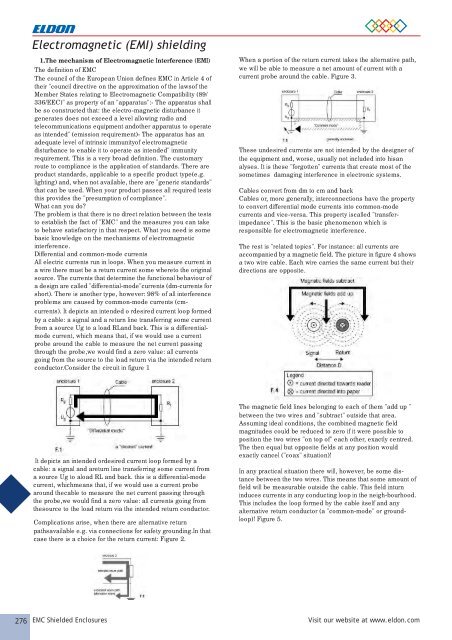
Electromagnetic (EMI) shielding<br />
1.1.The mechanism of Electromagnetic Interference (EMI)<br />
The definition of <strong>EMC</strong><br />
The council of the European Union defines <strong>EMC</strong> in Article 4 of<br />
their "council directive on the approximation of the lawsof the<br />
Member States relating to Electromagnetic Compatibility (89/<br />
336/EEC)" as property of an "apparatus":- The apparatus shall<br />
be so constructed that: the electro-magnetic disturbance it<br />
generates does not exceed a level allowing radio and<br />
telecommunications equipment andother apparatus to operate<br />
as intended" (emission requirement)- The apparatus has an<br />
adequate level of intrinsic immunityof electromagnetic<br />
disturbance to enable it to operate as intended" immunity<br />
requirement. This is a very broad definition. The customary<br />
route to compliance is the application of standards. There are<br />
product standards, applicable to a specific product type(e.g.<br />
lighting) and, when not available, there are "generic standards"<br />
that can be used. When your product passes all required tests<br />
this provides the "presumption of compliance".<br />
What can you do?<br />
The problem is that there is no direct relation between the tests<br />
to establish the fact of "<strong>EMC</strong>" and the measures you can take<br />
to behave satisfactory in that respect. What you need is some<br />
basic knowledge on the mechanisms of electromagnetic<br />
interference.<br />
Differential and common-mode currents<br />
All electric currents run in loops. When you measure current in<br />
a wire there must be a return current some whereto the original<br />
source. The currents that determine the functional behaviour of<br />
a design are called "differential-mode"currents (dm-currents for<br />
short). There is another type, however: 98% of all interference<br />
problems are caused by common-mode currents (cmcurrents).<br />
It depicts an intended o rdesired current loop formed<br />
by a cable: a signal and a return line transferring some current<br />
from a source Ug to a load RLand back. This is a differentialmode<br />
current, which means that, if we would use a current<br />
probe around the cable to measure the net current passing<br />
through the probe,we would find a zero value: all currents<br />
going from the source to the load return via the intended return<br />
conductor.Consider the circuit in figure 1<br />
When a portion of the return current takes the alternative path,<br />
we will be able to measure a net amount of current with a<br />
current probe around the cable. Figure 3.<br />
These undesired currents are not intended by the designer of<br />
the equipment and, worse, usually not included into hisan<br />
alyses. It is these "forgotten" currents that create most of the<br />
sometimes damaging interference in electronic systems.<br />
Cables convert from dm to cm and back<br />
Cables or, more generally, interconnections have the property<br />
to convert differential mode currents into common-mode<br />
currents and vice-versa. This property iscalled "transferimpedance".<br />
This is the basic phenomenon which is<br />
responsible for electromagnetic interference.<br />
The rest is "related topics". For instance: all currents are<br />
accompanied by a magnetic field. The picture in figure 4 shows<br />
a two wire cable. Each wire carries the same current but their<br />
directions are opposite.<br />
It depicts an intended ordesired current loop formed by a<br />
cable: a signal and areturn line transferring some current from<br />
a source Ug to aload RL and back. this is a differential-mode<br />
current, whichmeans that, if we would use a current probe<br />
around thecable to measure the net current passing through<br />
the probe,we would find a zero value: all currents going from<br />
thesource to the load return via the intended return conductor.<br />
Complications arise, when there are alternative return<br />
pathsavailable e.g. via connections for safety grounding.In that<br />
case there is a choice for the return current: Figure 2.<br />
The magnetic field lines belonging to each of them "add up "<br />
between the two wires and "subtract" outside that area.<br />
Assuming ideal conditions, the combined magnetic field<br />
magnitudes could be reduced to zero if it were possible to<br />
position the two wires "on top of" each other, exactly centred.<br />
The then equal but opposite fields at any position would<br />
exactly cancel ("coax" situation)!<br />
In any practical situation there will, however, be some distance<br />
between the two wires. This means that some amount of<br />
field will be measurable outside the cable. This field inturn<br />
induces currents in any conducting loop in the neigh-bourhood.<br />
This includes the loop formed by the cable itself and any<br />
alternative return conductor (a "common-mode" or groundloop)!<br />
Figure 5.<br />
276 <strong>EMC</strong> Shielded Enclosures Visit our website at www.eldon.com