PhilipsRadios.nl
PhilipsRadios.nl
PhilipsRadios.nl
- No tags were found...

Create successful ePaper yourself
Turn your PDF publications into a flip-book with our unique Google optimized e-Paper software.
PHILIPS<br />
PM 3370 LABORATORY PLUG-I N OSCI LLOSCOPE<br />
941 033 70011<br />
OPERATING MANUAL<br />
11670101
2<br />
IMPORTAI\IT<br />
In correspondence concerning this apparatus, please<br />
quote the type number and thc serial number as given<br />
on the type plate at the rear of the apparatus.<br />
N.V. PHILIPS'GLOEILAMPENFABRIEKEN . EINDHOVEN . THE NETHERLANDS - I97O
PHILIPS<br />
industrial<br />
equipment<br />
division<br />
L7 -9-1 970 GENERAL cd 667<br />
TtrST AND MtrASURING INSTRUMENTS<br />
RE: TEST INSTRUMENTS FOR OSflLLOSCOPES<br />
The importance of using appropriate test and calibrating instruments for pre-sa1e testing and servicing<br />
of equipment Ís now generally recognised. After careful study, in co-operation with development<br />
and quality-control specialists, we compÍled a recommanded list especially for oscilloscopes.<br />
Depending on the local needs and availabilities, we advise the National Service Organizations to<br />
consider investing in the following test instruments.<br />
A. REAL-TIME OSCILLOSCOPES<br />
a. C.alibraUng deflecti<br />
b. Checking the square-wave response of probes and attenuators<br />
For a) and b) use Oscilloscope Calibrator, type 156, by G & E Bradley Ltd, Electrical House, '<br />
Neasden Lane, London NW10, England.<br />
c. Checking bandwidthx)<br />
For the new procedure. applicable to PM 3200, PM 3210, PM 3220/2L, PM 3230, PM 3231, PM 3250<br />
and future oscilloscopes or units up to 10i MHz bandwidth, a constant amplitude generator, a 50 O<br />
cable and a 50 O termination pad, ordering code PM 9585 (i.e. type XE 101 96) are required.<br />
The advised generator is Tektronix type 191.<br />
In general, an oscilloscope may be rejected when the ggof the tolerances of the oscilloscope under<br />
test and the measuring instrument are exceeded.<br />
d. Checking rise timesx)<br />
For this check we recommend square-wave generator Tektronix type 284. As under c) the generator<br />
should be connected via a 50 g cable, terminated by a 50 O pad. The rise time of the generator<br />
should be taken into account and preferably be checked with a samplÍng oscilloscope, e. g. PHILIPS<br />
PM 3400.
e. Checking pulse response (overshoot, ringing etc. )*)<br />
The generator mentioned under d), should be connected via a 50 0 cable and a General Radio power<br />
divider, type 874-TPD, terminated at the oscilloscope input by a 50 O termination pad, General<br />
Radio type 874-WM.<br />
A sampling oscilloscope e.g. PM 3400 must also be connected to the power divider in order to<br />
check the pulse form to which the display on the oscilloscope under test should be refemed.<br />
f. Checking trigger functions<br />
PHILIPS Sine-wave Generator type PM 5125 (or PM 5160) is recommended for this check.<br />
g. To check the PM 3370 main frame. use the PHILIPS Test Unit PM 3363<br />
B. SAMPLING OSCILLOSCOPES<br />
a. Checking the triggering and the time-base circuitx)<br />
For the checking of these circuits we recommend the use of Tektronix Pulse Generator type 284.<br />
PHILIPS Digital Multimeter Pls.{242L, PHILIPS Timer/Counter PM 6630, a 10 dB attenuator e.g.<br />
General Radio 874G10, a 50 O cable and a 50 g termination pad e.g. PM 9585.<br />
b. Checking mÍxer and deflection amplifier<br />
For these checks we recommend the use of PHILIPS Digital Multimeter<br />
4822 320 10012.<br />
PM242L and a 50 O e.g.<br />
c. Checking the stabilized supply voltages and the low-voltage rectÍfier<br />
The recommended instrument for this check Ís the PHILIPS Digital Multimeter PM 2421 which<br />
should be connected to the circuits under test via a screened cable.<br />
d. Checking the sampliag amplifierx)<br />
For this check .ve recommend the use of Tektronix Pulse Generator type 284, two 6 dB attenrr;rtors<br />
e.g. General Radio 874G6, one 20 dB attenuator e.g. General Radio 874G20 and a 50 O cable with<br />
a length of
c. SURVEY OF THE RECOMMENDED INSTRUMENTS<br />
Oscilloscope Calibrator<br />
G&E BRADLEY type 156<br />
Constant -amplitude generator<br />
Square -wave generator<br />
Sampling oscilloscope<br />
Sine -wave generator<br />
Digital multimeter<br />
Test unit<br />
Counter/Timer<br />
Square -wave generator<br />
Termination pad<br />
Termination pad<br />
Power divider<br />
6 dB attenuator<br />
10 dB attenuator<br />
20 dB attenuator<br />
50 O cable 20 cm<br />
50 A cable 60 cm<br />
BNC T piece<br />
BNC-GR adapter<br />
tr<br />
TEKTRONIX type 191<br />
TEKTRONIX type 284<br />
PHILIPS type PM 3400<br />
PHILIPS type PM 5125 or PM 5160<br />
PHILIPS type PM 242L<br />
PHILIPS type PM 3363<br />
PHILIPS type PM 6630<br />
PHILIPS type PM 5770<br />
PHILIPS type PM 9585<br />
GENERAL RADIO type 874-WM<br />
GENERAL RADIO type 874-TPD<br />
GENERAL RADIO type 874G6<br />
GENERAL RADIO type 874c10<br />
GENERAL RADIO type 874c20<br />
PHILIPS code 482232010009<br />
PHILIPS code 482232010012<br />
AMPHENOL type UG-274V<br />
GENERAL RADIO type 874487A<br />
x) BNC and General Radio plugs can be coupled vla General Radio Adapters type 874-QB?A<br />
>
PHILIPS<br />
1{.V. PH IIIPS' GTOEI tAiI PE IIFABRIETEil. EIl{ DHOYEl{ . IIEDERtAl{D<br />
Í.-<br />
Circular letter to the T&M Service lvÍa nager<br />
Conf identia 1<br />
-l<br />
Tcl. Adr.: PHI!lPE<br />
ElllDH0YEll<br />
t_<br />
Re.<br />
-J<br />
From dcpt. - Du dópt. - Von Abt.<br />
Service P. I. T.<br />
BH/FS/9729.<br />
Conc. - Bctr. Tcl. Elndhovcn óOOOO - Ert. -<br />
App.<br />
Date - Detum<br />
I<br />
H.F. oscilloscope PM 3370 and<br />
Y plug-in unit PM 3372,<br />
4-3-t97 |<br />
The current input (input f) of all PM 3370 main frames with serial<br />
numbers ftom D772, has been nodified in order to obtain optimum<br />
pulse response.<br />
A series network (90.9O, 1.2 pF, 90.9 Q) has been connected betr,reen<br />
the input terminals of unít 12. Consequently, all Y plug-in units<br />
W,3372 from serial number D670 have been adjusted before Leavíng<br />
the factory, to suít the requirements of the modified PM 3370.<br />
Wtren such a PM 3372 with a serial number fron D670 is used with a<br />
pre-rnodification PM 3370 nain frame (i.e. a naín frame with a<br />
serial number prior Eo D772), an ovêrshoot of approxinately 8 Z<br />
on Èhe pulse will be observed. For this reason, rre are currently<br />
supplying all PM 3372lïl afi, -/O2 units complete with a package<br />
containíng tno 90.9 íl resístors (ordering number 5322 | l6 50799)<br />
and one 1.2 pF capacitor (ordering number 5322 122 3OlO2) together<br />
with the enclosed service infornation sheet Cd 690 which recomrends<br />
the PM 3370 nodification.<br />
Those Wl 3372 units with serial numbers prior to D670 will give an<br />
8 Z undershoot (rounding off) during the first 6 ns of the puLse<br />
when used ín conjunction with a nodified PM 3370 main fra.me. In this<br />
case, ne recoÍmend a h.f. readjustment or the return of the PVI 3372<br />
to Eindhoven for this readjustment.<br />
The readjustment wil-l be done free of charge, provided thaË the units<br />
concernêd arê rêturned before December 3lr 1971. Each readjusted unit<br />
returned by us will bear a sticker which states that the readjustment<br />
has been made.<br />
For fixed conbinations of unuodified main frames and Pl"l,3372 units with<br />
serial numbers prior to D670 the above mentioned rnodification and h.f.<br />
readjustmenË arê not necessary.<br />
2E22 | 00 05002
Circular<br />
Conf idential,<br />
Letter to<br />
the T&lí Service<br />
Manager.<br />
'2' 4-3- 197 | .<br />
Tes r uni r PM 3363<br />
The test unitp pupplied heve also becn edjusted to neet the requirenenrs<br />
of the nodified PU 3370.<br />
rf a PM 3363 unit ie used to chêck input r of a pt'Í 3370 naín frane<br />
whlch has not been nodified, we rec@ênd that the rnain frane in questíon<br />
is teryorariJ.y nodified for the duraÊÍon of rhe check.<br />
Ng.te<br />
Returne can o<strong>nl</strong>y be aceeptêd if Bhc goods arê returned without charge<br />
to us, and provided theÈ they have been allocated a reference number<br />
which uay be obtained from Mr. Potter, PXT Service, Eindhoven.<br />
p . p . N. V. PHILTPS<br />
I GIOEIIAI'íPENFABRTEKEN.<br />
Enelosura: cd 690.
PHILIPS<br />
industrial<br />
equipment<br />
division<br />
1-3-19?1 PM ggtz/ o. cd 690<br />
In the main frames PM 33?0 with serlal numbers from D7?2 onwards, a modification has been<br />
incorporated in the current input (input I) which is used for h.f. units.<br />
Your unit PM 3372 (and all units PM 33?2 with serial numbers from D670 onwards) has been<br />
àdjusted in a modified frame PM 33?0.<br />
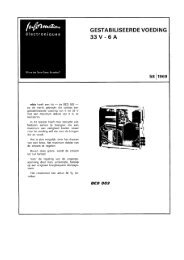
If your main frame carries a serial number below D772, the enclosed netrvork (2x90. 9 0 and<br />
1.2 pF) should be fitted on to the input terminals of unit.12 of your main frame (Fig. 1).<br />
This will result in an optimumpulse response and obviates further recalibration orh,f.<br />
readjustment of your PM 3370.<br />
11BU-Y<br />
7BU{<br />
a<br />
23BU-Y<br />
Fig. l. Part of the printed circuit board at the rear of the Y plug-in compartment.<br />
9499 448 03911
Contents<br />
GENERAL INFORMATION<br />
f. Introduction<br />
rr. Specification<br />
A. Electrical<br />
B. Physical<br />
Page<br />
8<br />
8<br />
9<br />
9<br />
l1<br />
rII.<br />
Principles of operation<br />
A. Y Signal Path<br />
B. Trigger Path<br />
C. Delayed Time-Base Principles<br />
D. Display Modes<br />
E. Miscellaneous Circuits<br />
F. Detailed Operation of the<br />
Tirne-Base Generators<br />
15<br />
15<br />
15<br />
r6<br />
t7<br />
18<br />
18<br />
I}IRECTIONS FORUSE<br />
Installation<br />
A. Mains Adjustments and Fuses<br />
B. Earthing<br />
C. Plug-in Units<br />
D. Switching On<br />
2T<br />
22<br />
22<br />
22<br />
22<br />
22<br />
v.<br />
Operation instructions<br />
23<br />
A. Controls 23<br />
B. Operating and Applications 25<br />
Voltage Measurements 25<br />
Time and Frequency Measruements 26<br />
Comparison of Methods 28<br />
Time Ratio Measurements 30<br />
Display Switching 31<br />
Phase Measurements 32<br />
Photographing Screen Traces 32<br />
Triggering<br />
Y Output Signal<br />
32<br />
34<br />
TJ
4<br />
List of illustrations<br />
Fig.<br />
1<br />
2<br />
3<br />
4<br />
s<br />
5<br />
6<br />
7<br />
8<br />
9<br />
10<br />
11<br />
L2<br />
13<br />
l4<br />
15<br />
16<br />
L7<br />
18<br />
T9<br />
20<br />
2L<br />
22<br />
23<br />
24<br />
25<br />
26<br />
27<br />
Page<br />
General View 7<br />
PM 3370 - Block Diagram 13<br />
Derivation of Delayed Pulse 16<br />
Delayed Time-Base WaveforÍns<br />
l6<br />
Gating WaveforÍns of Delayed Time-Base L6<br />
Main Time-Base Display 17<br />
Main Time-Base Intensified Display 17<br />
Delayed Time-Base Display 17<br />
Alternate Time-Base Display 17<br />
Time-Base Generators - Block Diagram 19<br />
Saw-tooth Generator - Block Diagram 19<br />
Saw-tooth Generator Waveforms 19<br />
Measuring Peak-to-Peak Voltages 25<br />
Measuring Instantaneous Voltages 26<br />
Measuring Time Intervals 27<br />
Definition of Rise-Time 27<br />
Measuring Rise-Time 27<br />
Time Measurements 28<br />
Time Measurements using<br />
Delayed Time-Base<br />
Time Ratio Measurements<br />
Effective Use of Display Switching<br />
Main Time-Base Trigger Controls<br />
Effect of Double Triggering<br />
Double Triggering on Pulse Trains<br />
Double Triggering in ALTERN. Mode<br />
Double Triggering in CHOPP. Mode<br />
Using the Y Output Signal<br />
29<br />
30<br />
31<br />
32<br />
33<br />
33<br />
33<br />
34<br />
34
sf2 s!(3 sK4<br />
-t/tft<br />
BUI<br />
LA3<br />
LA4<br />
SK9<br />
R3<br />
R4<br />
R5<br />
Ró<br />
I<br />
sK13<br />
sK14<br />
sKl5<br />
BU2<br />
6<br />
LA7<br />
Rr0<br />
SKIó<br />
nrr/srrz<br />
nra/sKrB<br />
BU3<br />
LA8<br />
SKI9 BU4 SK2O<br />
Fig. I. Generctl View
GENERAL INFORMATION<br />
This section of the instruction manual deals with introductory<br />
material and basic information of interest<br />
to both operating and servicing personnel.<br />
It includes specifications of physical and electrical<br />
ciata and a description of the operating principles of<br />
the instrument to block diagram level.<br />
The three chapters found in this section are:<br />
r. INTRODUCTION<br />
II.<br />
III.<br />
SPECIFICATION<br />
PRINCIPLES OF OPERATION<br />
l. Introduction<br />
The PM 3370 oscilloscope, shown in Fig. l, is a<br />
general-purpose instrument designed for a wide range<br />
of laboratory applications. This versatility is achieved<br />
by a series of modular plug-in units cach covering<br />
one or more aspects of the applications field.<br />
All Y plug-in units of the PM 33 . . series can be<br />
accommodated with the exception of the LF unit<br />
PM 3351. Choise of a plug-in unit, for example, permits<br />
the display of multi-trace signals, up to four,<br />
either separately or in combination. A dual-trace unit,<br />
the PM 3372, provides for a deflection coefficient of<br />
I mV/cm and a bandwidth of 150 MHz.<br />
A signal delay line permits the leading edges of fast<br />
signals to be displayed. Detailed observation of complex<br />
signals on an expanded time-base is facilitated<br />
by means of a built-in delayed time-base generator.<br />
For ease of operation, the delayed time-base generator<br />
controls are arranged in conformity with those of the<br />
main time-base generator. Each time-base has its<br />
own trigger unit.<br />
Further attention has been paid to the ergonomic<br />
layout of 'other front-panel controls: the colour<br />
matching of controls that are located in separate<br />
groups but have interdependent functions also facilitates<br />
operation of the oscillcscope.<br />
The PM 3370 incorporates a rectangular, flat-faced<br />
cathode ray tube with an illuminated internal graticule<br />
with obviates measuring errors due to parrallax.<br />
The use of silicon transistors throughout the oscilloscope<br />
results in a high degree of reliability.<br />
Provision is made for mains operation over the range<br />
I l0 V to 245 V by means of a series of primary connections<br />
on the mains transformer.
v<br />
ll. Specification<br />
Properties expressed in numerical values with stated<br />
Iolerances are guqranteed lor nominal mains voltages.<br />
Numerical values without tolerances serve as a guide<br />
and represent the characteristics ol an average instrument,<br />
A. ELECTRICAL<br />
I. C.RT. CIRCUIT<br />
t<br />
c.RT.<br />
Type<br />
Dl3-451 GH/45, rectangular with internal graticule.<br />
vz<br />
Effective screen area<br />
6 cm r l0 cm<br />
Phosphor medium long (P3l)<br />
Total accelerator voltage<br />
15 kV<br />
Unblanking<br />
d.c. coupled<br />
Graticule<br />
internal with continuous control of illumination.<br />
External Z Modulation<br />
5 V peak+o-peak signal required at 500 Hz to 50 MHz for visible<br />
intensity modulation.<br />
Beamfinder<br />
push-button for reducing deflection sensitivity for locating the trace on<br />
the screen.<br />
2. Y CHANNEL<br />
Final Amplitier<br />
Type<br />
Delay<br />
Rise-time<br />
-<br />
,<br />
d.c. amplifier<br />
by internal delay line (delay 80 ns), effective delay )20 ns.<br />
input I: 1.7 ns (equivalent bandwith 210 MHz)<br />
input II: 5 ns (equivalent bandwith 70 MHz)<br />
Plug-in units PM 3332. PM 3334, PM 3342. PM 3344 and<br />
PM 3379 automatically use input Il.<br />
Y Output<br />
Coupling<br />
Volts out<br />
Resistance out<br />
If Y Output terminated with 50 Q<br />
Volts out<br />
Bandwidth<br />
Plug-in Unit<br />
a.c. coupled, fra" low 1 kHz<br />
1 Y / cm deflection of the trace;<br />
9 V maximum.<br />
200 Q<br />
| 200 mV / cm deflection of the trace;<br />
,- 1.8 V maximum.<br />
100 kHz to 50 llu'.{Hz<br />
See the relevant specification of the plug-in unit in use.<br />
Calibration Unit<br />
Voltage<br />
for R1 : 50 Q: 40 mV, 80 mV. 200 mV, 400 mV peak-to-peak<br />
for Rt : 500 Q: 4 V Peak-to-Peak<br />
''ív Tolerance * lVo<br />
Frequency<br />
2 kHz square wave voltage
10<br />
Current<br />
Tolerance<br />
Frequency<br />
8 mA peak-to-peak maximum<br />
'f lVo<br />
?, kHz square wave current<br />
3. X CHANNEL<br />
Deflection Modes<br />
- Main time-base<br />
- Main time-base intensified<br />
- Delayed time-base<br />
- Alternate between main time-base intensified and delaved time-base<br />
- External<br />
Main Time-base<br />
Sweepspeeds<br />
50 ns/qn to 1 s/cm (1,2,5 sequence) in 23 calibrated steps. Continuous<br />
control between steps (uncalibrated)<br />
Tolerance -l 3Vo 1+ 5Vo in I s/cm position)<br />
Magnification<br />
l0 X (+ 2Vo)<br />
with maximum magnification the fastest sweep speed is 5 ns/cm<br />
Mode<br />
automatic (AUTO)<br />
triggered (TRIGG.)<br />
single shot (SINGLE)<br />
Triggering Source<br />
internal (INT.)<br />
external (EXT.)<br />
internal at mains frequency (MAINS)<br />
Slope * or -<br />
Coupling<br />
(LF) 3 Hz to 1 MHz<br />
(HF) 2 kHz to full bandwidth<br />
(DC) 0 to full bandwidth<br />
Sensitivity<br />
with external triggering;<br />
200 mV (LF and HF coupling)<br />
400 mV @C coupling)<br />
With internal triggering see the specification of the Y plug-in unit in use.<br />
Input Impedance of Trigger Input I MQ, 15 pF<br />
Level<br />
Internal: continuously adjustable over 6 cm<br />
External: continuously adjustable over 3 V peak-to-peak for medium<br />
frequencies (range can be magnified 5 X )<br />
Main Timebase Intensified<br />
In this position, the portion of the main time-.base<br />
which coincides with the delayed sweep is intensified.<br />
The intensity ratio is adjustable by means of the<br />
INTENS. RATIO control.<br />
Delayed Time-base<br />
Sweepspeeds 50 ns/cm to 1 s/cm (1,2,5 sequence) in 23 calibrated steps. Continuous<br />
control between steps (uncalibrated).<br />
Tolerance * 3Vo (+ 5% in I r/ position)<br />
"-<br />
Magnification<br />
10 X (+ 2Vo)<br />
With maximum magnification the fastest sweep speed is 5 ns/cm<br />
Mode<br />
Selected by AFTER DELAY TIME switch;<br />
STARTS immediately after delay time,<br />
EXT. TRIGG. after delay time,<br />
INT. TRIGG. after delay time.
11<br />
Slope<br />
Coupling<br />
Sensitivity<br />
Input impedance<br />
Level<br />
Delay<br />
Jitter<br />
Alternate between<br />
Main Time-base Intensified<br />
and Delayed Time-base<br />
as detailed for main time-base<br />
adjustable up to 10 seconds. Incremental multiplier linearity, typically<br />
O.ZVo.<br />
3<br />
Y- PLUG<br />
---'l<br />
I<br />
I<br />
FROM<br />
Y-PLUG-IN<br />
UN IT<br />
IN PUT I<br />
INPUT II<br />
DE LAY- LINE<br />
DRIVER<br />
DELAY-LINE<br />
Y- OUTPUÏ<br />
AMPLIFIEF<br />
BEAM<br />
FINDER<br />
TRIGGER IN<br />
__J<br />
I<br />
EXTERNAL<br />
Y-OUTPUT<br />
AMPLIFIER<br />
Y- OUTPUT<br />
TRACE SEF<br />
TRIGGER<br />
AM P LIFIE R<br />
SET READY<br />
.AUTC<br />
O TRIG(<br />
OSIN GL<br />
SOU R CE<br />
COUPLING<br />
LEVE L<br />
TRIGGER<br />
O INT.<br />
O EXT.<br />
OMAINS<br />
TRIGGER<br />
PULSE<br />
SHAPE R<br />
SLOPE<br />
DEL'D TR I6(<br />
TRIGGER<br />
AFTER DELAY TIME<br />
O STARTS<br />
O EXT.<br />
R IGGE RABLE<br />
O INT.<br />
TRIGGE RABLE<br />
COU P LING<br />
LEVEL<br />
TRIGGER<br />
PULSE<br />
SHAPER<br />
S LOPE<br />
x - tNPur oF-<br />
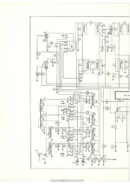
F'ig.2. PM 3370 - Block Diagram<br />
SIMPLIFIED BLO
E.H.T. UN IT<br />
Z.MOD @4-1<br />
l<br />
\<br />
INTENS.<br />
FOCUS ASTIGM<br />
UNBLANKING<br />
CIRCUIT<br />
--.<br />
+GATE SWEEP<br />
MAIN TIME BASE<br />
\y<br />
TIME/cm 0R<br />
DELAY TIME<br />
COMPARATOR<br />
DI SPLAY<br />
SWITCH<br />
o MAIN T.B<br />
. MAIN T.B.<br />
- INTENS<br />
O ALTE RN<br />
TIME BASE<br />
AM PLIF IER<br />
.Y<br />
} GATE<br />
SWEEP<br />
X-INPUT<br />
P0sliloN<br />
DELAYED TIME BASE<br />
\l-l<br />
TIME/cm<br />
POWE R SUPPLY<br />
PRE AMP.<br />
CALIBRATION UNIT<br />
CK DIAGRAM PM 3370<br />
MA 5677
15<br />
lll. Principles of oPerotÍon<br />
A simplified block diagram of the PM 3370 oscilloscope<br />
is shown in Fig. 2. The functions of the<br />
various blocks can best be understood by considering<br />
first of all the Y signal and trigger paths and secondly<br />
the time-base circuits.<br />
A. Y SIGNAL PATH<br />
The Y deflection signal, derived from the Y plug-in<br />
unit, is applied symmetrically to the delay-line driver.<br />
Delay-line Driver<br />
The delay-line driver has two inputs, a current input<br />
(input I) and a voltage input (input II). The requisite<br />
input is selected automatically on the insertion of a<br />
plug-in unit. The units already available for the<br />
60 }l.{Hz plug-in oscilloscope PM 3330, i.e., units<br />
PM 3332, PM 3334, PM 3342 and PM 3344,use the<br />
voltage input (input II).<br />
Rise-time<br />
The rise-time for the current input is | .7 ns. For<br />
example, when using the dual-trace plug-in unit<br />
PM 3372:<br />
Total rise-time - V1.7, + 1.72 : 2.4 ns approx.<br />
The rise-time for the voltage input is 5 ns. When using<br />
one of the units mentioned above:<br />
Total rise-time - /t 52 nanoseconds<br />
l, u*<br />
The delay-line driver provides two outputs, one for<br />
the delay line and the other to feed an external Y<br />
amplifier.<br />
Externat Y Output Amplifier<br />
This amplifies one of the outputs from the delay-line<br />
driver to provide an a.c. coupled Y output, available<br />
at a socket on the rear of the instrument, e.9., for<br />
triggering purposes when signals, not related in time,<br />
are displayed using a multi-trace unit in the ALTERN.<br />
mode.<br />
Delay Line<br />
The delay line, fed from an output of the delay-line<br />
driver, consists of two standard 75-ohm coaxial cables,<br />
each 18 m long, giving approximately 80 ns<br />
delay. This standard cable has both ends terminated<br />
to minimize reflections.<br />
Y Output Amplifier<br />
The signal from the delay line is amp,lified in the Y<br />
output amplifier stage before being passed to the<br />
segmented Y deflection plates of the cathode ray tube.<br />
B. TRIGGER PATH<br />
The trigger signal from the Y plug-in unit is fed to the<br />
trigger amplifier. The output of the trigger amplifier is<br />
passed to the trigger circuits of the main time-base and<br />
the delayed time-base.<br />
Source Selector<br />
The main time-base trigger circuit accepts this signal<br />
when the three-position source selector switch<br />
is in the INT position. The EXT TRIGG position<br />
permits the time-base to be triggered by an external<br />
signal applied at the EXT TRIGG socket. In the<br />
MAINS position a signal derived from the mains<br />
transformer provides the triggering facility.<br />
Coupling Selector<br />
The three-position coupling solector switch permits<br />
the frequency range of the trigger amplifiers to be<br />
reduced to remove interfering frequency components<br />
(hum or noise) from the trigger signal. In the LF<br />
position the range is from 3 Hz to I MHz, in the HF<br />
position the range is from 2 kHz to the upper limit<br />
of the bandwidth and in the DC position the range<br />
covers the whole bandwidth (0 to upper limit).<br />
Trigger Pulse Shaper<br />
In the trigger pulse shaper circuit a d.c. voltage is<br />
added to the trigger pulse, adjustable by the LEVEL<br />
potentiometer, to shift the trigger point. The control<br />
knob has a "pull-push" action which in the "pull"<br />
position increases the external trigger range by a<br />
factor<br />
"f<br />
The trigger signal can be reversed in polarity by<br />
means of the SLOPE switch ( + -) to permit triggering<br />
by the positive-going or negative-going edge<br />
of the trigger signal.<br />
Main Time-base Operating Modes<br />
The trigger pulse shaper converts the trigger signal<br />
into sharp positive and negative pulses. The negative<br />
pulses áre used to trigger the time-base generator,<br />
while the positive pulses are used in the automatic<br />
free-run circuit. The saw-tooth voltage from the main<br />
time-base generator is fed to the time-base amplifier<br />
in the MAIN T.B. and MAIN T.B. INTENS.<br />
positions of the X DEFL. switch.
t6<br />
Three modes of operation of the main time-base are<br />
determined by the three-position switch AUTO/<br />
TRIGG/SINGLE.<br />
In the AUTO mode, the automatic free-run circuit is<br />
operative when triggering pulses aÍe absent. Thus a<br />
trace, though not necessarily a station ary one, is always<br />
displayed even though the trigger controls may<br />
not be correctly adjusted. In this wêy, correct adjustment<br />
of the oscilloscope trace is greatly facilitated.<br />
However, when trigger pulses aÍe present the circuit<br />
reverts to the normal triggered mode. If trigger pulses<br />
disappear, the time-base free-runs after a lapse of<br />
0.5 seconds. In the TRIGG. mode, a display is present<br />
o<strong>nl</strong>y when suitable trigger pulses are available.<br />
In the SINGLE mode, events that occur o<strong>nl</strong>y once can<br />
be observed and photographed if necessary. It is often<br />
desirable to ensure that o<strong>nl</strong>y one saw-tooth is generated,<br />
even though other trigger pulses might follow<br />
the phenomenon of interest. In this mode, after the<br />
trigger pulse has initiated the main time-babe to<br />
produce a saw-too'th voltage, the circuit is unaffected<br />
by further trigger pulses until it is either switched to<br />
the TRIGG. mode or reset for the next event by<br />
operating the SET READY push-button.<br />
C. DELAYED TIME.BASE PRINCIPLES<br />
The saw-tooth voltage derived from the main timebase<br />
generator is passed to a comparator where it is<br />
compared with an accurately adjustable d.c. voltage.<br />
The comparator output voltage is then pulse shaped<br />
by a reset multivibrator to provide the required delayed<br />
pulse. As indicated in the relevant waveforms<br />
of Fig. 3., the pulse shaper output voltage drops to<br />
its original value at the end of the forward sweep of<br />
the main saw-tooth voltage.<br />
the c.r.t. The time relationship between these wave.-<br />
forms is shown in Fig. 4.<br />
SAWTOOTFI VOLTAGE<br />
DEIÁYED PUI,SE<br />
Fig. 4. Delayed Time-Base Waveforms<br />
SAWIOOTH VOLTAGE OF<br />
DEIÁYED TIME.BASE<br />
UNBIÁNKING PULSE OF<br />
DEIÁYED TIME-BASE<br />
With the AFTER DELAY TIME switch in the<br />
START position, the delayed time-base starts immediately<br />
on receipt of a pulse from the reset multivibrator.<br />
Gated Operation of the Delayed Time-Base<br />
With the AFTER DELAY TIME switch in the INT.<br />
TRIGG. or EXT. TRIGG. position, the delayed<br />
trigger pulse prepares the time-base for the normal<br />
triggered mode of operation. The next trigger pulse<br />
from the internal trigger unit or from an external<br />
source (dependent on switch setting) arriving after<br />
the set delay time actuates the delayed time-base,<br />
which is then locked to this trigger signal. The waveforms<br />
of Fig. 5. illustrate this $ating procedure. The<br />
total delay is now the sum of the set delay time (i.e.,<br />
the product of the values indicated by the DELAY<br />
TIME and DELAY TIME MULTIPLIER controls)<br />
and the extra delay indicated in Fig. 5.<br />
SAWTOOTH VOLTAGE<br />
DEIÁYED<br />
PULSE<br />
OUTPUT OF COI\{PARATOR<br />
TRIGGER PUI,SES FROIVI THE<br />
DEIÁYED TRIGGER UNIT<br />
DEI,AYED PULSE<br />
DEIÁYED TRIGGER PUI-SE<br />
AVAII,ABLE AT o/P SocKET<br />
the dela.ved time-base !<br />
rll<br />
lll ,l<br />
SAWTOOT}I VOLTAGE OF<br />
DEIÁYED TIME -BASE<br />
UNBIÁNKING PULSE OF<br />
DEIÁYED TII\ÍE.BASE<br />
Fig. 3. Derivation oÍ Delayed Pulse<br />
Fig. 5. Gating WaveÍorms of Delayed Time-Base<br />
The delayed pulse is fed to the delayed time-base<br />
generator which then initiates a saw-tooth voltage<br />
and an unblanking pulse, both of which are fed to<br />
The remainder of the<br />
time-base generator is<br />
time-base generator.<br />
trigger circuit for the delayed<br />
identical to that for the main
7<br />
D. DISPLAY MODES<br />
A choise of five different modes of display is possible<br />
by means of the X DEFL. selector switch.<br />
the gating pulse from the delayed tirne-base is fed<br />
to the control grid of the c.r.t. As a result, the intensified<br />
portion of the display, produced by the<br />
previous setting, is now expanded to fill the entire<br />
screen.<br />
MAIN T.B.<br />
When the X DEFL. switch is set to MAIN T.8., a<br />
saw-tooth voltage derived from the main time-base<br />
generator is fed via the time-base amplifier to the<br />
horizontal deflection plates of the cathode ray tube.<br />
In addition, the gating pulse from the main timebase<br />
is applied to the control grid (Wehnelt cylinder)<br />
of the c.r.t. via the unblanking circuit in order to intensify<br />
the trace during the sweep.<br />
TRIGGER FJLSE 3<br />
C:LAY:D;IMg 3J.SE<br />
SÀVJTOOTH VOLTA:.:<br />
UNELANK ING PULSE<br />
Fig. 8. Delayed Tíme-Base Dísplay<br />
TRIGGER PULSES<br />
ÈtAIIJ TIME EASE<br />
SAWTOOTH VOLTAGE<br />
UNELANKING PULgE<br />
Fig. 6. Main Time-Base Display<br />
MAIN T.B. INTENS.<br />
When the X DEFL. switch is set to MAIN T.B.<br />
INTENS. the saw-tooth voltage derived from the<br />
main time-base generator is again fed to the c.r.t. via<br />
the time-base amplifier. However, in this position of<br />
the X DEFL. switch, the gating pulses from the main<br />
time-base and the delayed time-base are combined<br />
and applied to the control grid of the c.r.t. During the<br />
operation of the delayed time-base generator the<br />
trace undergoes extra intensification. The start of the<br />
intensified portion can be shifted by means of a tenturn<br />
potentiometer, the DELAY TIME MULTI-<br />
PLIER. The brightness of the non-intensified portion<br />
of the trace can be adjusted by means of the<br />
control INTENS. RATIO.<br />
Fig. 7. Main Time-Base Intensified Display<br />
DEL'D T.B.<br />
When the X DEFL. switch is set to DEL'D T.B. the<br />
saw-tooth voltage from the delayed time-bêse, generator<br />
is fed to the deflection plates of the c.r.t. and<br />
ALTERNI.<br />
When the X DEFL. switch is set to ALTERN. an<br />
electronic switch enables the display of Fig. 7 and<br />
the display of Fig. 8 to be alternately traced on the<br />
screen. The two displays can be separated by varying<br />
the voltage applied to the vertical amplifier, derived<br />
from the driving circuits of the electronic switch. This<br />
separation is symmetrically variable by means of the<br />
TRACE SEPARATION control.<br />
TRI6GER PULSES<br />
SAVJÏOOTH VOLTAGE<br />
UIiSLANKI:JG PULSE<br />
Fig. 9. Alternate Tíme-Base Display<br />
VIA X INPUT<br />
When the X DEFL. switch is set to VIA X INPUT,<br />
this permits an external voltage to be applied to the<br />
X pre-amplifier to provide horizontal deflection via<br />
the time-base amplifier. The deflection coefficient is<br />
l0 mV/cm with a bandwidth from d.c. to I MHz.<br />
A I -to-l0 continuous gain control, incorporated in<br />
the X pre-amplifier, provides for a deflection range<br />
from l0 mV/cm to 100 mVlcm. The deflection<br />
coefficient may be increased by a factor of ten by<br />
means of a pull switch integral with the gain control.<br />
This provides for a total range from 10 mV/cm to<br />
I Y /cm.<br />
This facility can be used for XY applications, where<br />
phase relationships between the X and Y deflections<br />
above 50 kHz are not important. This limit is imposed<br />
because of the presence of the delay line in<br />
the Y amplifier.
18<br />
E. MISCELLAIYEOUS CIRCUITS<br />
Time-Base Amplifier<br />
The main function of this amplifier is to amplify the<br />
saw-tooth voltages produced by the time-base generators.<br />
In order to improve linearity and accuracy.<br />
the circuit is designed so that the currents drawn by<br />
output transistors increase during the linear part of<br />
the sweep. The gain of the amplifier can be increased<br />
by a factor of ten (MAGN. control) resulting in a<br />
maximum sweep rate of 5 ns/cm. For a detailed<br />
description of this circuit see Chap. 6.<br />
Unblantriry Circuit<br />
The unblanking pulses from the two time-base generators<br />
are fed, via the unblanking circuit, to the<br />
Wehnelt cylinder of the c.r.t. The d.c. coupling of<br />
this circuit is rcalised by means of a modulator and<br />
a d.c. restorer. For a detailed description of this<br />
circuit see Chap. 6.<br />
Calibration Unit<br />
This unit supplies the voltages for the calibration of<br />
the deflection coefficient and for probe adjustments.<br />
Voltages of 400 mV, 200 mV, 80 mV and 40 mV<br />
are available with an internal resistance of 50 ohms.<br />
A voltage of 4 V is available with an internal resistance<br />
of 500 ohms. The square wave delivered has a<br />
frequency of.2kIIz. Calibration surrents can be made<br />
available for current probes by short-circuiting the<br />
output terminal. A detailed description is given in<br />
Chap.6.<br />
Power Supplies<br />
The power supplies, which are electronically stabilised,<br />
are protected against overloads and shortcircuits.<br />
Automatic reset facilities are provided. For<br />
a detailed description of these circuits see Chap. 6.<br />
E.H.T. Power Supply<br />
The e.h.t. voltage is obtained by transforming and<br />
rectifying the output voltage of a 40 kHz push-pull<br />
oscillator. This power supply delivers:<br />
- + 13,000 V with respect to earth, for post-deflection<br />
acceleration. The rectifying circuit comprises<br />
a voltage tripler.<br />
- -2,000 V with respect to earth, (stabilised) the<br />
cathode potential of the cathode ray tube.<br />
This power supply is also protected against overloads<br />
and short-circuits. For a detailed description of the<br />
polver supply see Chap. 6.<br />
Beamfinder<br />
To facilitate rapid location of an image, the oscilloscope<br />
is fitted with a beamfinder.<br />
When the BEAMFINDER push-button is pressed,<br />
the amplification factors of the X and the Y amplifiers<br />
are reduced so that the electron beam deflection<br />
is confined to the display area of the c.r.t. It is<br />
then a simple matter to centre the image by means<br />
of the position controls.<br />
F. DETAILED OPERATION OF<br />
THE TIME.BASE GENERATORS<br />
This section gives a more detailed description of the<br />
functional operation of the time-base generators with<br />
the aid of the block diagram. Fig. 10. Details of the<br />
individual units is given in the Circuit Description,<br />
Chapter 6.<br />
Main Time-Base<br />
The timing of the main time-base is controlled by the<br />
sweep gating multivibrators (SGM). The input signal<br />
to the SGM is the sum of three signals:<br />
the negative trigger pulses,<br />
the hold-off pulse,<br />
a d.c. voltage from the AUTO circuit.<br />
When the SGM is triggered by the trigger pulse, a<br />
voltage step is applied to the integrator which results<br />
in a voltage, increasing linearly with time, at the<br />
output of the integrator; the forward sweep voltage.<br />
This voltage is also passed via the hold-off circuit to<br />
the hold-off multivibrator, a Schmitt trigger. At a predetermined<br />
level, the hold-off multivibrator switches,<br />
to produce a hold-off pulse, the leading edge of which<br />
resets the SGM to its original state. This causes the<br />
integrator output voltage to fall exponentially to its<br />
original value, relatively quickly: the flyback time<br />
period. The hold-off pulse, of longer duration than<br />
this period, keeps the SGM insensitive to further<br />
trigger pulses until the flyback is complete. The output<br />
voltage of the hold-off circuit then decreases by<br />
an amount such that the hold-off multivibrator is<br />
reset, thus allowing the SGM to be triggered again.<br />
If the mode switch is in the AUTO position, positive<br />
trigger pulses from the pulse shaper produce a positive<br />
voltage at the AUTO circuit output. As a positive<br />
voltage does not affect the norÍnal functioning of the<br />
time-base generator, as described above, normal triggered<br />
operation is obtained. However, when trigger<br />
pulses cease to arrive at the AUTO circuit, its output<br />
voltage decreases. At a certain moment, the SGM<br />
input voltage becomes so low that the saw-tooth<br />
generator commences to free run.
t9<br />
FROM TRIGGER PULSE SHAPER<br />
I<br />
T<br />
I<br />
SWEEP GATING<br />
MULTIVIBRATOR<br />
ïlME/cm<br />
OR DELAY TlME<br />
-A<br />
VOLTA6E<br />
CURRE NÏ<br />
CONVERTER<br />
VOLTA6E<br />
CURRENT<br />
CONVERTER<br />
+ GATE<br />
TO INTENSITY<br />
CONTROL CIRCUIT<br />
TO TIME-BASE<br />
AMPLIF IE R<br />
HOL D -OF F<br />
CIRCUIT<br />
AU TO<br />
T R IGGE<br />
S INGLE<br />
tr<br />
ALTERNATE PULSE<br />
FOR<br />
Y - PLUG - IN UNIT<br />
EM ITTER<br />
FOLLOWER<br />
SWEEP<br />
TO INPUT<br />
OF ELECTRONIC SWITCH<br />
RESET<br />
CIRCUIT<br />
DELAY TIME<br />
MULTIPLIER<br />
COM PARATOR<br />
RESET<br />
MULTIVIERATOR<br />
EMITTER<br />
FOLLOWER<br />
DE L'D SWEEP<br />
HOLD -OFF<br />
MULTIVIBRATOR<br />
DELAYED TRIGGER PULSE<br />
TO TIME-BASE<br />
FROM TRIGGER PULSE<br />
SHAPER<br />
SWEEP GATING<br />
MULTIVIBRATOR<br />
AMPLIFIER<br />
AFTER<br />
TIME<br />
DELAY<br />
T lM E/cm<br />
VOLTAGE<br />
CURREN T<br />
CONVERTER<br />
TO UNELANKING<br />
CIRCUlT<br />
DEL'O GATE<br />
CLIPPER<br />
VOLTAGE<br />
CURREN T<br />
CONVERT E R<br />
TO UNBLANKING<br />
CIRCUIT<br />
Fig. 10. Time-Base Generators - Block Diagram<br />
BLOCK OIAGRAM OF IHE IIME-BASE GENERATORS<br />
Hotd-otf<br />
time<br />
TRIGGER<br />
PULSE<br />
SGM<br />
OUT PUT<br />
PULSE<br />
ÏIME.8ASE<br />
SI6NAL<br />
TIME- BASE<br />
SIGNAL<br />
SAW-TOOTH GENERATOR BLOCK OIAGRAM<br />
HOLD-OFF<br />
PULSE<br />
MA 5683<br />
SAW -TOOÏH GENERATOR WAVEFORMS<br />
F ig. I I . Saw-tooth Generator - Block Diagram<br />
Fig. 12. Saw-tooth Generator Wavelorms
20<br />
If the mode switch is in the TRIGG. position, the<br />
output of the AUTO circuit is disconnected from the<br />
SGM and the main time-base operates in its normal<br />
triggered mode. In the SINGLE position of the mode<br />
switch, the input d.c. level of the hold-off circuit is<br />
such that the hold-off multivibrator is switched to<br />
the hold-off position. When the SET READY pushbutton<br />
is pressed, the hold-off multivibrator is switched<br />
back so that the SGM responds to trigger pulses<br />
again. A pilot lamp indicates the state of the holdoff<br />
multivibrator.<br />
Delay Circuit<br />
The delay time multiplier supplies an adjustable d.c.<br />
voltage to the comparator to provide a reference<br />
level with which the saw-tooth voltage of the main<br />
time-base is compared.<br />
Immediately the saw-tooth voltage approximates this<br />
level, the comparator delivers a square wave signal<br />
which persists until the end of the flyback. This signal<br />
is applied via the reset multivibrator to the hold-off<br />
multivibrator of the delayed time-base to activate<br />
the delayed sweep.<br />
Delayed Time-Base<br />
The delayed time-base is similar to the main timebase<br />
but lacks the AUTO and hold-off circuits. Its<br />
operation is identical to that described for the main<br />
time-base in the single-sweep mode except that the<br />
hold-off circuit is not operated by the SET READY<br />
push-button but by pulses from the reset multivibrator.<br />
The d.c. level applied to the SGM input is determined<br />
by the position of the AFTER DELAY TIME<br />
switch. The various positions of this switch influence<br />
the delayed time-base as follows:<br />
STARTS - the delayed time-base starts immediately<br />
on receipt of a pulse from<br />
the reset multivibrator;<br />
INT. TRIGG. - the delayed time-base is set ready<br />
)<br />
to start on receipt of the next internal<br />
trigger pulse;<br />
EXT. TRIGG. - the delayed time-base is set ready<br />
to start on receipt of the next external<br />
trigger pulse.
2t<br />
\-/<br />
DIRECTIONS FOR USE<br />
This section of the instruction manual is essentially<br />
of interest to operating personnel. It deals with the<br />
information necess ary for installing and operating the<br />
equipment correctly, outlines its capabilities, reviews<br />
basic measuring principles and suggests techniques<br />
for obtaining the best results in various applications.<br />
v
22<br />
lV. fnsto llation<br />
The PM 3370 oscilloscope is despatched complete<br />
with the following accessories which are stowed, for<br />
transit, in the packing space above the instrument.<br />
Thes,e items are:<br />
1. a mains lead with connector,<br />
2. a shorting link for calibrating current probes,<br />
3. a viewing hood,<br />
4. a green filter,<br />
5. an instruction manual,<br />
6. a BNC 4 mm adaptor,<br />
7. a BNC-BNC cable.<br />
On receipt, remove these accessories and the instrument<br />
from the carton and examine them to ascertain<br />
whether any damage has been sustained in transit.<br />
Remove each of the side covers by means of the two<br />
quick-release fasteners located near the top corners.<br />
Check that all printed circuit cards are fully inserted<br />
and visually inspect the interior. Replace the side<br />
covers by first inserting the lower edges in the appropriate<br />
recesses at the base of the instrument.<br />
A. MAINS ADJUSTMENTS & FUSES<br />
Before switching otr, the instrument should be adjusted<br />
to the local mains voltage by means of the<br />
voltage adaptor on the rear panel. Provision is made<br />
for selecting 110 V, 125 V, 145 V, 200 V, 220 V<br />
and 245 V. The voltage selected is displayed through<br />
an ap€rture in the cover plate.<br />
The fuse-holder on the rear panel normally carries<br />
a 2.5 A mains fuse but if the instrument is to be connected<br />
to a mains voltage of less than 200 V, the 5 A<br />
fuse supplied should be fitted. The 5A fuse is<br />
mounted on top of the screening partition over the<br />
Y plug-in compartment.<br />
A thermal cut-out is incorporated as an integral part<br />
of the mains transformer to prevent excessive overheating<br />
in the event of a prolonged short circuit.<br />
B. EARTHING<br />
In the interests of safety, the instrument should be<br />
earthed via one of the earth terminals (+) on the<br />
front or rear panel, or via the mains flex if this has a<br />
plug with an earth connection.<br />
NOTE: Double-earthing n;ust be avoided as this may<br />
couse hum on the trace.<br />
C. PLUG.IN UNITS<br />
The instrunent normally operates o<strong>nl</strong>y if one of the<br />
Y plug-in units, listed in the specification, has been<br />
inserted. A push-button, situated below the aperture<br />
for the plug-in unit, provides for the release of a unit<br />
from the multi-way socket of the main frame to aid<br />
extraction.<br />
D. SWITCHING ON<br />
The instrument is switched on by means of the<br />
POWER ON switch. The white pilot lamp, adjacent<br />
to the switch, illuminates to indicate this condition<br />
when the mains are connected and the POWER ON<br />
switch is in the "up" position.<br />
Under normal laboratory conditions, a warm-up<br />
period of about fifteen minutes is generally sufficient<br />
before accurate measurements are taken. If the oscilloscope<br />
has been subjected to abnormally low temperatures<br />
or to extrenie humidity, the warm-up period<br />
should be extended accordingly.<br />
WARNING:<br />
This instrument generates high voltage and should<br />
not be operated with the side panels removed. The<br />
mains plug should be removed before attempting any<br />
maintenance work, and qny relevant high voltage<br />
points discharged.
23<br />
V. Operoting ÍnstructÍons<br />
Before switching on, ensure that the oscilloscope has<br />
been correctly installed in accordance with Chap-<br />
ter IV, INSTALLATION, and that the precautions<br />
outlined have been observed.<br />
A. CONTROLS (refer to fig. l)<br />
Main Time-base Generator<br />
INT/EXTIMAINS (SK4) trigger source, three-position switch:<br />
INT: trigger signal derived from Y plug-in unit.<br />
EXT: trigger signal derived from a voltage applied to the TRIGG.<br />
BNC socket. (BUl)<br />
MAINS: trigger signal at mains frequency derived internally from<br />
mains transfoÍïner.<br />
LFIHF/DC (SK3)<br />
trigger coupling, three-position switch:<br />
LF: via a band-pass filter for frequencies from 3 Hz to 1 MHz.<br />
HF: via a high-pass filter for frequencies above2kHz.<br />
DC: direct coupling for triggering on a slowly varying voltage, or for<br />
full bandwidth working.<br />
+ /- (SK2) slope control, two-position switch:<br />
provides for triggering on the positive-going or the negative-going slope<br />
of the signal.<br />
LEVEL (Rl/SKl)<br />
AUTO/TRIGG/SINGLE(SK5)<br />
SET READY (SK8)<br />
TIME/cm or DELAY TIME (SK6)<br />
CAL (TIME/cm) (R2ISK7)<br />
Delayed Time-base Generator<br />
continuously adjustable control to select the level at which the main<br />
time-base triggers. Incorporates a pull switch for X 5 increase of external<br />
trigger range.<br />
time-basemode,three-positionswitch:<br />
AUTO: the time-base is free-running in the absence of trigger signals.<br />
TRIGG: the time-base is triggered normally.<br />
SINGLE: the time-base sweeps o<strong>nl</strong>y once.<br />
reset push-button for the SINGLE position of the time-base mode<br />
switch.<br />
time coefficient control of main time-base, 23-way switch.<br />
continuously variable control of time coefficient of main time-base. In<br />
the CAL. position the time coefficient is calibrated.<br />
AFTER DELAY TIME (SK15)<br />
LF/HF/DC (SK14)<br />
three-position mode switch:<br />
STARTS: sweep starts immediately after delay time.<br />
EXT. TRIGG: can be triggered from external source (BU2) after delay<br />
time.<br />
INT. TRIGG: can be triggered from internal source after delay time.<br />
trigger coupling, three-position switch:<br />
LF: via a band-pass filter for frequencies from 3 Hz to I MHz.<br />
HF: via a high-pass filter for frequencies above 2 kHz.<br />
DC: direct coupling for triggering on a slowly varying voltage, or for<br />
full bandwidth working.
A<br />
+ /- (SK13) slope control, two-position switch:<br />
provides for triggering on the positive-going or the negative-going slope<br />
of the sigral.<br />
LEVEL (R9/SK12)<br />
TIME/cm (SK16)<br />
CAL(TIME/cm) (Rll/SK17)<br />
continuously adjustable control to select the level at which the delayed<br />
time-base triggers. Incorporates a pull switch for X 5 increase of external<br />
trigger range.<br />
time coefficient control of delayed time-base, 23-way switch.<br />
continuously variable control of time coefficient of delayed time-base.<br />
ln the CAL. position the time coefficient is calibrated.<br />
DELAY TIME ten-turn helipot control of delay time used in conbination with the -<br />
MULTIPLIER (RlO)<br />
DELAY TIME controls of the main time-base.<br />
v<br />
Horizontal Amplifier Controls<br />
X POSITION (R7lR8)<br />
MAGN (SK10)<br />
X DEFL (SKl1)<br />
Miscellaneous Confrols<br />
TRACE SEPARATION (R12)<br />
INTENS. RATIO (R13)<br />
mV/cm (X INPUT) (R14/SK18)<br />
CAL. (SK2O)<br />
POWER ON (SK19)<br />
Cathode Ray Tube Controls<br />
BEAMFINDER (SK9)<br />
INTENS. (R3)<br />
FOCUS (R4)<br />
ASTIGM. (R5)<br />
ILLUM. (R6)<br />
continuously variable control giving coarse and fine (vernier) horizontal<br />
positioning of the display.<br />
push-button control for X 10 magnification of horizontal deflection.<br />
time-base selector, five-position switch:<br />
MAIN TB: horizontal defiection is achieved bv main tirne-base.<br />
MAIN TB<br />
INTENS.: horizontal deflection is achieved by the main time-base,<br />
the part of the trace coinciding with the delayed sweep<br />
being intensified. The intensity ratio is adjustable (see<br />
Miscellaneous Controls).<br />
ALTERN.: horizontal deflection is achieved by the main time-base<br />
intensified and the delayed time-base alternately. Vertical<br />
trace separation and intensity ratio are adjustable (see<br />
Miscellaneous Controls).<br />
DEL'D TB: horizontal deflection is achieved by delayed time-base.<br />
via X INPUT: horizontal deflection is achieved by an external source<br />
via X INPUT socket (BU3). Deflection coefficient is<br />
. adjustable (see Miscellaneous Controls).<br />
continuously variable control providing vertical trace separation.<br />
continuously variable control for adjusting the intensity ratio in the<br />
MAIN TB INTENS. and ALTERN. positions of the X DEFL. switch.<br />
continuously variable control for X deflection, from external source<br />
(BU 3) with integral X 10 pull switch attenuator.<br />
six-position switch for selecting calibrated 2 kHz square-waves of<br />
various amplitudes for calibration purposes, which are available at BU4.<br />
toggle switch for the mains supply to the oscilloscope.<br />
push-button to enable a trace to be readily located on the screen by<br />
reducing the deflection coefficients.<br />
variable control of trace brightness.<br />
variable control of electron beam focusing.<br />
variable control of trace astigmatism.<br />
variable control of graticule illumination.
25<br />
B. OPERA.TION & APPLICATIONS<br />
An oscilloscope designed for a wide range of applications<br />
is, inevitably, a complex instrument. As modern<br />
instruments offer more and more facilities, so the<br />
task of operating them increases in complexity. The<br />
PM 3370, although of logical design and built for<br />
ease of operation, may present some problems to the<br />
occasional operator confronted with such a large<br />
number of controls. However, an understanding of<br />
the techniques for making basic measurements together<br />
with a recognition of the less obvious triggering<br />
problems and their solution, should help to dispel any<br />
apprehension on the part of the user.<br />
Freliminary Adiustment of Y Amplifier<br />
Observe the preliminary setting-up instructions for the<br />
particular Y plug-in unit fitted. Assuming that a<br />
PM 3372 Dual-Trace Y Amplifier is fitted, the preset<br />
GAIN controls can be adjusted as follows. As the<br />
circuits are identical, o<strong>nl</strong>y the procedure for channel<br />
A has been described.<br />
With the oscilloscope correctly installed as outlined<br />
in the previous chapter, connect the CAL<br />
socket to the A input socket by means of a coaxial<br />
link.<br />
Select channel A on the display switch and DC on<br />
the AC/DC push-button.<br />
Set the mY / cm switch to 50 and ensure that the<br />
potentiometer is in the CAL position.<br />
Set the calibration output switch (CAL) to the<br />
200 mV position and check that the vertical deflection<br />
is exactly 4 cm (2 cm when the second A<br />
input is terminated in 50 A).<br />
Adjust the preset GAIN control to achieve this, if<br />
necessary.<br />
This procedure should be repeated for the B channel<br />
(and the C and D channels when a four-trace unit is<br />
fitted).<br />
Peak-to-Peak Voltage Measurements<br />
To measure the peak-to-peak voltage value of the a.c.<br />
component of a waveform, connect the signal to one<br />
of the Y input sockets and adjust the Y plug-in unit<br />
controls in accordance with the operating instructions<br />
to display as large a trace as possible. Then proceed<br />
as follows:<br />
1 . set the TIME / cm switch to display a few cycles<br />
of the waveform as illustrated; (fig. I 3)<br />
2. adjust the Y POSITION control so that the lower<br />
peaks of the waveform coincide with the nearest<br />
horizontal graticule line;<br />
3. adjust the X POSITION control so that one of<br />
the upper peaks coincides with the centre vertical<br />
graticule line;<br />
4. measure the vertical distance between the peaks<br />
of the signal;<br />
5. multiply this measured distance by the voltage<br />
setting of the Y amplitude switch and by the attenuation<br />
factor of the probe, if any.<br />
Fig. 13. Measuring Peak-to - Peak Voltages<br />
a<br />
II<br />
VOLTAGE MEASUREMENTS<br />
Display the waveform as large as possible when<br />
making voltage measurements in order to obtain<br />
maximum accuracy. For all voltage measurements,<br />
the Y / cm potentiometer on the Y plug-in unit must<br />
be in the CAL position, otherwise the deflection coefficients<br />
are not calibrated.<br />
When using a X l0 probe, observe that the displayed<br />
amplitude must be multiplied by a factor of 10.<br />
Ensure that the probe is adjusted for good step response,<br />
and, in the interests of accuracy, that the Y<br />
GAIN preset is re-adjusted before use.<br />
Example 1.<br />
Assume that the Y amplitude switch is set to 2 mV/cm<br />
and a l0 : I attenuator probe is used. The measured<br />
vertical distance is 4.6 cm.<br />
Using the formula:<br />
voltso.o- t 1Y ampl'1 /o.t"ot)<br />
fYt:ttt1]<br />
\oirtunr")x \ setting )x \atten./<br />
. - 4.6 x 2 x l0<br />
If the waveform is a pure sine wave the r.m.s. voltage<br />
. Vo-o<br />
itft:32.5<br />
92 mY<br />
mV
26<br />
Instantaneous Voltage Measurements<br />
To measure the instantaneous value of a waveforffi,<br />
coÍrnect the signal to one of the Y input sockets and<br />
adjust the Y plug-in unit controls in accordance with<br />
the operating instructions, to display as large a trace<br />
as possible. Then proceed as follows:<br />
1. set the Y input to zeÍo (CHEK ZERO pushbutton)<br />
and adjust Y POSITION control so that<br />
the zeÍo reference line coincides with the nearest<br />
horizontal graticule line;<br />
NOTE: The Y POSITION control must not be<br />
moved alter this reference line has been<br />
established;<br />
2. release the CHECK ZERO push-button and select<br />
DC;<br />
3. rotate the X POSITION control so that the point<br />
to be measured lies on the vertical centre-line;<br />
4. measure the vertical distance between this point<br />
and the zero reference line; if the point lies above<br />
the reference line, the voltage is positive, if it lies<br />
below the line, the voltage is negative;<br />
5. multiply themeasured distance by the Y amplification<br />
setting and the attenuation factor of the<br />
probe, if any.<br />
NOTE: To meosure a voltage level with respect to<br />
another voltage rother than with earth, apply<br />
the relerence voltage to the ínput socket and<br />
the Y POSITION control so that the trace<br />
coincides with a horizontal graíicule line,<br />
which can now be used as the reference linc.<br />
T his replaces the zero ref erence procedure<br />
descríbed ín step I .<br />
TIME AND FREQUENCY MEASUREMENTS<br />
For all time and frequency measurements, the TIME/<br />
cm potentiometer must be in the CAL position, otherwise<br />
the deflection coefficients are not calibrated.<br />
To reduce reading error, time and frequency measurements<br />
can be made by using the delayed sweep timebase.<br />
Time Measurements<br />
To measure the time interval between two points of a<br />
wavefoÍffi, connect the signal to one of the Y input<br />
sockets and adjust the Y plug-in unit controls in<br />
accordance with the operating instructions, to display<br />
as large a trace as possible. Then proceed as follows:<br />
1 . set the TIME / cm switch so that the horizontal<br />
distance between the time rneasuring points is as<br />
large as possible;<br />
2. rotate the X POSITION control so that one of<br />
the measuring points coincides with its nearest<br />
vertical graticule line;<br />
3. rotate the Y POSITION control to bring the other<br />
point to the horizontal centre-line;<br />
4. measure the horizontal distance between the two<br />
time measurement points;<br />
5. multiply the measured distance by the TIME/cm<br />
setting. (If magnification is used, divide this<br />
product by 10.)<br />
a II<br />
frequency -<br />
F'ig. I4. M easuring Instantaneous V oltages<br />
Example 2<br />
Assume that the Y amplitude switch is set to 0.5 V/cm<br />
and that a 10 : I attenuator probe is used. The<br />
measured vertical distance is 3.2 cm. (Fig. 14)<br />
Using the formula:<br />
: (il;#;,)'<br />
Instantaneous lYertícal\ lY ampl.\ / Pto:.t,^-\<br />
Voltage ( '#il l. t,ïï;ï""/<br />
:3.2 X0.5 X10<br />
- 16 Volts, of positive polarity.<br />
Example 3.<br />
Assume that the TIME / cm setting is 0. 1 ms and the<br />
magnifier is on. The measured distance is 7 .5 cm.<br />
Applying the formula:<br />
Time<br />
horizontal distance X TIME/cm setting<br />
interval<br />
magnification<br />
'7.5 x 0.1 ms<br />
10<br />
: 0.075 ms - 75 ps<br />
Hence, the frequeocy, which is the reciprocal of the<br />
time duration of one cycle, can be easily calculated,<br />
viz.<br />
1<br />
: '/.,3 lrJlz<br />
75 x 106
27<br />
horizontal distance<br />
To measure the rise-time of a signal, connect the<br />
t<br />
signal to one of the Y input sockets and adjust the Y<br />
-7,5cm<br />
plug-in controls in accordance with the operating<br />
instructions to display as large a trace as possible.<br />
Then proceed as follows:<br />
1. set the TIME / cm switch of the main time-base to<br />
display the total voltage step on the screen;<br />
2. adjust the Y amplitude so that the vertical deflection<br />
is exactly six centimetres.<br />
The l0 % and 90 % points now coincide with<br />
the dotted lines of the graticule.<br />
3. adjust the X POSITION control so that the l0 Vo<br />
coincides with the nearest vertical graticule line;<br />
this line is now the time reference line, and no<br />
FiS. 15. Measuring Time Intervals<br />
further adjustment of the X POSITION control<br />
should be made;<br />
Rise-time Measurements<br />
4. measure the horizontal distance between the time<br />
reference line (coincident with the l0 Vo point)<br />
Rise-tirne is defined as the time required by the<br />
and the point of intersection of the signal and the<br />
leading edge of a signal to rise from l0' Vo to 90 Vo horizontal 90 Voline.<br />
of the amplitude, as shown in Fig. 16.<br />
5. The rise-time is given by the product of the horizontal<br />
distance in centimetres and the TIME / cm<br />
setting. If magnification is used, this product must<br />
be divided by 10.<br />
Example 4. (see fig. 17)<br />
Assume that the TlME/setting is 200 ns and no<br />
magnification is used. Assume a total oscilloscope<br />
rise-time of 0.35ps is obtained with the PM 3372 set<br />
accordingly.<br />
measured rise-time<br />
TIME / cm setting X Horizontal distance<br />
Magnification<br />
200 ns X 2.7<br />
- 540 ns<br />
1<br />
Fí5. 16. DeÍinition of Rise-Time<br />
Substituting in the formula:<br />
When the oscilloscope rise-time is comparable witir actual rise-time<br />
the signal under test, the actual rise-time should be<br />
/<br />
calculatedas follows:<br />
y'm:O.4lps<br />
Actual t. - 1/ (measured t,)' (oscilloscope t,)'<br />
The length of the resultant<br />
arrow gives the displayed<br />
rise-time. The same time-scale<br />
must be used Íor all three<br />
vectors.<br />
o<br />
a.<br />
o<br />
U 14<br />
e<br />
1.,<br />
UI<br />
o<br />
o<br />
I<br />
3<br />
2.t,<br />
2<br />
1<br />
12315578<br />
tr of signol +<br />
Oscilloscope Ríse-Time<br />
versus Sígnal Rise-Time.<br />
MA 568 0<br />
Fig. 17. Measuring Rise-Time
28<br />
Accuate Time M-asurements using<br />
theDelayd Time-base<br />
The delayed sweep is invaluable for making accurate<br />
time measurements.<br />
The advantages of using the delayed time-base method<br />
can best be understood if we consider the factors that<br />
contribute towards measurement errors when using<br />
an oscilloscope.<br />
These are:<br />
a. the inaccuracy of the time-base,<br />
b. the reading error.<br />
The inaccuracy of the time-base is generally specified<br />
for the middle 8 divisions of the deflection (due to<br />
slight nonJinearities at the extremes of the scan) a<br />
tolerance of approximately 3 Vo being common for<br />
professional equipment. This is often regarded as the<br />
measuring error of the oscilloscope, the reading error<br />
generally being neglected. However, this latter error<br />
can have considerable influence on the accuracy of<br />
the measurement. The factors that influence the<br />
reading error are:<br />
- line thickness,<br />
- the angle between the signal and the horizontal<br />
graticule line at the point where the reading is<br />
made,<br />
- parallax.<br />
Line thickness is dependent on the focussing and<br />
astignatism of the c.r.t. spot and upon its intensity.<br />
For optimum line thickness, the intensity should not<br />
be too high.<br />
The angle between the sigral and the horizontal<br />
graticule line at the point of reading should be as<br />
large as possible to obtain a clearly defined crossover<br />
point. It is therefore advisable to work with the<br />
biggest possible display and, if possible, to take the<br />
reading at the steepest part of the trace.<br />
With the PM 3370, the reading error due to parallax<br />
is eliminated as the c.r.t. has an internal graticule.<br />
The value of the reading error which results from<br />
taking measurements may be as much as 0.05 of a<br />
centimetre for each measuring point. As all time<br />
measurements are in fact the result of two measurements,<br />
the total reading eÍïor can be 0.1 of a centimetre.<br />
This is an additional factor contributing towards<br />
the total inaccuracy, and for measurements<br />
over small distances it adds a considerable error to<br />
the reading. For example, over two centimetres<br />
0.1<br />
-XlO0Vo:SVo.<br />
2<br />
By using the delayed sweep method.of measurement<br />
it is possible to considerably reduce the influence of<br />
the reading error.<br />
The following methods illustrate the various uses clf<br />
the delayed time-base. Note that the DELAY TIME<br />
MULTIPLIER potentiometer introduces a slight inaccuracy<br />
due to its non-linearity which is 0.1 Vo<br />
maximum.<br />
COMPARISON OF METHODS<br />
The attendant advantages of measuring tirne differences<br />
by means of the delayed time-base can be<br />
shown by considering a specific example and applying<br />
the various methods of measurement at our disposal.<br />
Example 5.<br />
Assume a signal as illustrated in Fig. I 8, where it is<br />
required to measure the time difference between the<br />
points tr, tz, tr, t+.<br />
Fig. 18. Time Measurements<br />
Method A.<br />
Measuring the tirne difference by means of. the main<br />
time-base.<br />
Assume that the TIME/cm setting of the main timebase<br />
is 10 ps/cm and that the horizontal distance t1<br />
and ta, is 8.2 cm. The measured time difference between<br />
them is therefore 8.2 X 10 ps - 82 ps. The<br />
measured distance t2 t3 is 0.2 cm which represents<br />
2 ps. The measured distance t3 - ta is 1.4 cm which<br />
represents 14 pS. Therefore, the reading errors for<br />
the respective times are:<br />
0.05<br />
tr-tc_2 X X lO}Vo: + l.zVo<br />
8.2<br />
0.05<br />
tz-h:2 x x l00vo: + Sovo<br />
0.2<br />
0.05<br />
tr-te :2 X X I0O%_ t7%<br />
r.4
29<br />
As the error of the time-base may be as mucir as 3 Vo,<br />
this must be taken into account when calculating the<br />
total error.<br />
Note: The figure Íor the time-base error con be<br />
checked by displaying on accurotely known<br />
f requency.<br />
It will be observed that the accuracy is rapidly degraded<br />
as the distance on the time axis decreases. For<br />
distances less than I cffi, the X l0 MAGN. can be<br />
used. In the example for tz-tt, the distance is expanded<br />
to L7 cm, which gives 1.7 ps.<br />
0.05<br />
The reading error is 2 X X 100 Vo - 6 Vo<br />
1.7<br />
Therefore the max. total error could be<br />
3% + zVo + 6Vo: ll %<br />
The 2 Vo error factor is due to the use of the X 10<br />
magnifier.<br />
By using this method, the accuracy is improved by a<br />
factor of 5.<br />
Method B.<br />
Measuring the time difference by means of the<br />
delayed time-base.<br />
V/ith the X DEFL switch set to MAIN TB INTENS,<br />
the DELAY TIME MULTIPLIER potentiometer<br />
may be adjusted in conjunction with the TIME / cm<br />
switch of the delayed time-base to give an intensified<br />
display of that portion of the trace which embraces<br />
tz- tE.'<br />
By switching the X DEFL switch to DEL'D TB an<br />
expanded image, as shown in Fig. 19, is obtaineci.<br />
Fig. 19. Ttme Measurements usíng Delayecl Time-<br />
Base<br />
Assume that the TIME / cm setting of the delayed<br />
time-base is 0.2 ps/cm. The measured distance between<br />
t2 and t3 is now 8.2 cm and t2 - t3 is 1.64 ps.<br />
The read-off error exp;essed as a percentage is now:<br />
0.05<br />
2 x - X 100 Vo : l.2Vo<br />
8.2<br />
The total measuring error is thus 3 + 1.2 : 4.2 Vo.<br />
When t3-t4 is measured by the same method, the<br />
largest distance on the time axis will be a setting of<br />
2 ps/cm for the delay time-base. The distance is 6.8<br />
cm, therefore, the time is 13.6 ps, and this reading<br />
error is 1.5 Vo giving a total error of |.5 Vo * 3 Vo<br />
: 4.5 Vo.<br />
Method C.<br />
Measuring the time difference by means of the delayed<br />
time-base and the DELAY TIME MULTIPLIER.<br />
Obtain an expanded display as in the previous method,<br />
then rotate the TIME/cm switch of the delayed timebase<br />
to 100 ns/cm so that the trace is expanded by a<br />
factor 100. Locate tz on the screen and align it with<br />
the vertical centre-line of the graticule by means of<br />
the DELAY TIME MULTIPLIER dial. Note the<br />
dial reading.<br />
Then rotate the dial until t3 coicides with the vertical<br />
centre-line and note the new dial reading.<br />
If these readings are, for example, 7.08 and 6.92, then<br />
the dial distance between the two measuring points<br />
has been expanded to 1.6 cm and the time difference<br />
is 16 x 100 ns : 1.6 ps.<br />
The total measuring error using this method, is the<br />
sum of the. maximum main time-base error and the<br />
error due to the nonJinearity of the DELAY TIME<br />
MULTIPLIER potentiometer (0.27o) together with<br />
the read-off error.<br />
The read-off error is now the sum of the error caused<br />
by shifting both measuring points to the vertical centre-<br />
0.05<br />
line; i.e., a maximum of 2 x - x IO0 Vo : 6.3 Vo.<br />
1.6<br />
Thus the maximum total error : 3 Vo * O.2 Vo *<br />
0.63 Vo + 6.3 Vo lO Vo.<br />
Measuring tr-to in -, the same manner will give dial<br />
readings of 7.08 and 8.445 so the difference is 1.365.<br />
Thus the distance between the two measuring points<br />
has now been expanded to 136.5 crn, the time difference<br />
being 136.5 x 100 ns : 13.65 ps.<br />
The reading error on the display is<br />
0.1<br />
- x IOO Vo : O.O7 Vo<br />
1.365<br />
0.01<br />
the dial read-off error is X 100 Vo : O.'l Vo<br />
1.365<br />
therefore, the total error : 3 % + O.2 Vo * O.O7 Vo<br />
+ 0.7Vo:4Vo.
30<br />
Measuring t1 ta with method C<br />
reading difference of 8 .21. The tirne<br />
ps and the expanded distance is 821<br />
0. I<br />
error of the display is x 100<br />
821<br />
will give a dial<br />
is therefore 82.1<br />
crn. The reading<br />
Vo - 0.012 %<br />
0.01<br />
which can be neglected.'The dial reading eÍïor is -<br />
8.21<br />
X 100 % - 0.12 Vo which makes the total error<br />
3 % + 0.2 % + 0.12 Vo :' 3.3 Vo.<br />
Conclusions<br />
I nterval<br />
X 1MAGN.<br />
METHOD A<br />
X 1MAGN.<br />
METHOD B<br />
METHOD C<br />
tt - t+<br />
tz-tl<br />
tl-t+<br />
82ps + 4.3%<br />
2ps+53 %<br />
l4ps + l0 %<br />
l.7ps + tl% l.6ps + 4.2%<br />
l3.6ps + 4.s%<br />
82ps + 3.3yo<br />
l.6ps :E l0 %<br />
l3.65ps + 4 %<br />
It will be seen from the table of results that Method B<br />
is best when very small distances on the main timebase<br />
axis are to be measured. However, when these<br />
distances are greater than about I cffi, the read-off<br />
error of the DELAY TIME MULTIPLIER becomcs<br />
negligible and Method C is to be preferred.<br />
TIME RATIO MEASUREMENTS<br />
The delay time multiplier offers the facility for the<br />
accurate determination of time ratios. Any significant<br />
errors incurred are due o<strong>nl</strong>y to the incremental no<strong>nl</strong>inearity<br />
of the ten-turn potentiometer, and to the<br />
reading error which can be kept small by using the<br />
delayed time-base.<br />
This is illustrated by reference to the following example.<br />
(fig. 20)<br />
The purpose of the measurement is to find the mark/<br />
space ratio of the signal. For suitable expansion of<br />
the leading and trailing edges, the delayed time-base<br />
TIME / cm switch rwas set to 1 ps/cm.<br />
The negative-going leading edge was dialled to the<br />
centre vertical graticule line, as illustrated, and the<br />
dial setting of the DELAY TIME MLILTIPLIER<br />
noted; this was 1.770. Then the next positive-going<br />
edge was dialled to the vertical centre-line, the setting<br />
being 6.265. Similarly, the final negative-going edge<br />
was dialled and a reading of 8.21 obtained.<br />
Thus the negative-going portion of the trace gave a<br />
measured reading of:<br />
6.265-1.77: 4"495.<br />
The positive-going portion of the trace gave a measured<br />
reading of:<br />
8.21 -6.265:1.945.<br />
Therefore, the mark/space ratio is:<br />
1.945 : 0.433.<br />
4.495<br />
The. accuracy of the positive-going portion is determined<br />
by the reading eÍror and the incremental no<strong>nl</strong>inearity<br />
of the dial potentiometer.<br />
As the main time-base is expanded by a factor of.20,<br />
the pulse length is 20 X 1.945 - 38.9 cm.<br />
Therefore,<br />
FiS. 20. Time Ratio Measurements<br />
The upper trace shows the pulse displayed by the<br />
main time-base at the 20 ps/cm setting. The lower<br />
trace represents the intensified portion of the upper<br />
trace as displayed in the ALTERN. position of the<br />
X DEFL. switch.<br />
2 X 0.05 X L00 Vo<br />
reading error : : 0.26 Vo<br />
38.9<br />
2x 0.005 X 100 Vo<br />
clial reading erro r -<br />
: 0.5 Vo<br />
L.945<br />
potentiometer non-linearity : 0.2 Vo .<br />
Total accuracy for the positive-going portion is therefore:<br />
0.26 Vo + 0.5 Vo + 0,2 Vo : 0.96 Vo.
31<br />
For the negative-going portion:<br />
2 x 0.05 x 100 Vo<br />
reading error -<br />
dial reading error -<br />
0.1r %<br />
g9.9<br />
2 xo'oo5xloo%-0.23%<br />
4.495<br />
potentiometer non-linearity -<br />
0.2 Vo .<br />
Total accuracy for the negative-going portion is therefore:<br />
0.11 Vo + 0.23% + 0.2%-0.547o.<br />
The total ratio error is therefore:<br />
0.96 % + 0.54 % _ 1.4%.<br />
The resultant measurement gives a ratio of 0.433 +<br />
1 .4 Vo; i.e. within 0.427 and 0.439.<br />
Set the X DEFL. switch to ALTERN. and adjust<br />
the delayed time-base controls for a suitable display<br />
of the leading edge of the square wave (Fig. zlb).<br />
Adjust the Y deflection and POSITION controls<br />
of the plug-in unit and the TRACE SEPARATION<br />
control of the main instrument to remove the extreme<br />
traces of Fig. 2lb for clarity.<br />
By employing a multi-exposure photographic techruique,<br />
the relationship between input voltage and output<br />
rise-timc can be effectively displayed as illustrated<br />
in Fig. 2ic.<br />
Display Switching<br />
The PM 3370 is equipped with display switching, a<br />
new feature for the Philips range of oscilloscope. This<br />
rlow offers the instrument user a simultaneous display<br />
of the signal on the two time scales provided by the<br />
main time-base and by the delayed time-base.<br />
Detailed examination of a certain portion of the main<br />
time-base display is enabled by expanding the time<br />
interval of interest by means of the delayed time-base.<br />
Expansion is achieved by selecting a correspondingly<br />
faster sweep for the delayed time-base TIME / cm<br />
control, and positioning the time interval by the<br />
DELAY TIME MULTIPLIER poten,tiometer.<br />
The part of the signal under detailed observation by<br />
the delayed time-base appears as an intensified portion<br />
of the main time-base display. This not o<strong>nl</strong>y<br />
facilitates the location of the required detail during<br />
dialling but also serves as a visual indication of which<br />
portion of the overall trace is being examined. (See<br />
Fig. 20.) Thus the operator can immediately correlate<br />
the detail with the overall signal, which may be extremely<br />
complex, without the necessity of switching<br />
between MAIN T.B. and DEL'D T.B. as required<br />
with most other instruments.<br />
This feature is extremely useful when the aspects of<br />
the detail being observed are changes caused by the<br />
variation of some other signal displayed simultaneously<br />
by the main time-base.<br />
An example of this is shown in Fig. 2l where a sine<br />
wave of variable amplitude is fed into an overdriven<br />
amplifier which fr,rnctions as a squarer. The amplitude<br />
of the square wave output, u<strong>nl</strong>ike the rise-time, is<br />
independent of the input voltage. To examine the<br />
relationship between rise-time and input voltage, the<br />
following procedure may be employed.<br />
Using a multi-trace plug-in in the ALTERN. mode<br />
display the output voltage as the upper trace and<br />
the input voltage as the lower trace, as shown in<br />
Fig. 2la.<br />
u. Output signul (upper truc'e) of u .\quurer, dríven by {t<br />
sinusoïdal input (lower trac'e).<br />
h. ShowirtS1 the leuding edge (sec'ond<br />
wul'e .<br />
trac'e) of the squure<br />
c. Multi-exposure photogruph showirtg the rise-time varying<br />
with input amplitude.<br />
Fig. 21. EfÍective Use of Display Switching
32<br />
PHASE MEASUREMENTS<br />
To measure the phase difference between two sinusoidal<br />
signals of the same frequetrcy, use the following<br />
method.<br />
Connect one signal to one of the Y input sockets and<br />
the other signal to the other Y input socket of the<br />
PM 3372, using probes or coaxial cables with equal<br />
time delays. Display the traces using the AUTO<br />
mode of the main time-base with the Y select switch<br />
at CHOPP. (suitable for low frequencies) or ALT<br />
ERN. (suitable for high frequencies). If the signals<br />
are of opposite polarity then pull one of the Y POSI-<br />
TION controls to invert the lagging signal. Note that<br />
the total phase difference must be subtracted from<br />
180o in this event. With a stable display of maximum<br />
amplitude. adjust the Y POSITION controls for symmetry<br />
about the horizontal centre-line.<br />
Having set up the display, proceed as follows:<br />
1 . set the TIME / cm switch and potentiometer so<br />
that one cycle of the first signal occupies exactly<br />
9 cm horizontally; i.e., each cm represents 360"- /9<br />
- 40o;<br />
2. measure the horizontal distance between the two<br />
corresponding points on the waveforms, and<br />
multiply_this by 40o to obtain the phase differencé.<br />
If one of Y POSITION controls is inverted,<br />
subtract the result from 180o.<br />
NOTE: For small phase dillerences (less than 40" )<br />
use the X I0 MAGN. push-button and divide<br />
the result by I0. The phase scale rs now<br />
4"/cffi, therefore, the measured distance in<br />
centimetres should be multiplied by four to<br />
obtain the desired phase diÍference measurement.<br />
Small phase differences can also be measured by<br />
rneans of the delayed time-base.<br />
The total period, time T, is Íreasured by using the<br />
main time-base. Then the time difference dT is<br />
measured using one of the methods previously described,<br />
depending on the distance between the two<br />
measuring points.<br />
The ratio between this tin e duration dT and T, multiplied<br />
by 360 degrees gives the phase difference between<br />
the two signals.<br />
PHOTOGRAPHING<br />
SCREEN TRACES<br />
Photographic records of the screen traces can be made<br />
for periodic or single-shot events. Details are given<br />
in the rnanual of camera assembly PM 9380.<br />
TRIGGERING<br />
The precise functions of the trigger controls that are<br />
found on a niodern oscilloscope may not be wellknown<br />
to the occasional user. However, a brief excursion<br />
into the basic principles of triggering will<br />
facilitate correct adjustment of the controls.<br />
Put simply, triggering circuits have two main functions:<br />
I . to initiate a pulse at a predetermined point of the<br />
signal under observation,<br />
2. to start the sweep by means of this pulse.<br />
Figure 22 shows the PM 3370 main time-base trigger<br />
controls together with a brief explanation of their<br />
various functions.<br />
Initially, the four trigger controls may be set to the<br />
following positions; i.e., all in UP position:<br />
LEVEL mid-range<br />
SLOPE +<br />
COUPLING LF<br />
SOURCE INT.<br />
LEVEL<br />
PULL FOR x 5<br />
EX T. TRIGG. RANGE<br />
LEVEL CONTROL<br />
determines the d.c.<br />
level at which the oscilloscope<br />
will trigger. A<br />
signal passing through<br />
the desired level will<br />
o<strong>nl</strong>y trigger the oscilloscope<br />
if its direction<br />
is that selected by the<br />
SLOPE control.<br />
E-<br />
SLOPE CONTROL<br />
determines whether<br />
the oscilloscope will be<br />
triggered on a positivegoing<br />
slope, or on a<br />
negative-going slope of<br />
the signal.<br />
Fig. 22. Matn Time-Base Trigger Controls<br />
COUPLING<br />
CONTROL<br />
- determines the method<br />
of coupling the signal<br />
into the trigger circuit.<br />
LF coupling blocks<br />
undesired d.c. levels<br />
and h.f. interference<br />
but responds to l.f.<br />
triggering. HF coupling<br />
blocks d.c. and l.f. (e.g.,<br />
hum) but responds to<br />
h.f. triggering signals.<br />
DC coupling makes the<br />
full signal bandwidth<br />
available for triggering.<br />
IN T.<br />
EXT.<br />
MAINS<br />
SOURCE CONTROL<br />
determines the origin<br />
of the trigger source.<br />
INT. from the internal<br />
plug-in unit. (for<br />
multitrace units select<br />
the appropriate channel<br />
on the plug-in unit).<br />
EXT. from an external<br />
trigger source, via<br />
the TRIGG. input.<br />
MAINS from the<br />
mains transformer.<br />
1Mn<br />
15p F<br />
l,lA 569t<br />
TRIGGER INPUT<br />
- provides a high-impedance<br />
coaxial input<br />
(l MQ / / 15 pF) when<br />
triggering from an external<br />
source.
33<br />
With this configuration, ar display is generall.y produced<br />
which can then be easily adjusted to meet other<br />
requirements. Some of these applications are now<br />
considered with reference to the trigger control adjustments<br />
required for optimum display and measuremgnt.<br />
Double Triggering<br />
Double triggering is an effect, inherent in all triggering<br />
systems, that can be produced when the signal<br />
point at which the circuit triggers occurs more than<br />
once in a single repetition time T as shown in Fig. 23.<br />
This phenomenon is exhibited particularly in the<br />
display of pulse trains.<br />
Now because both time-base are of the same length<br />
the next flyback period will end after a second pulse<br />
in the waveform and the new sawtooth will again be<br />
triggered on the first-pulse. So the sawtooth waveform<br />
will be alternately triggered by the first and second<br />
pulses resulting in an oscillogram as illustrated in<br />
Fig. 24.<br />
If it is not possible to trigger on another pulse that<br />
occurs o<strong>nl</strong>y once during the repetition time T, and<br />
which is related to the displayed pulse (e.g. via the<br />
EXT. trigger input), then the obvious remedy is to<br />
vary the sweep speed by means of the continuous<br />
time-base control. If a calibrated display is required,<br />
then the alternative is to vary the time-base switch<br />
control in steps to eliminate the double triggering.<br />
However, if this produces an unsatisfactory time-base<br />
speed, the display can be rectified by switching the<br />
TIME / cm potentiometer to the UNCAL position and<br />
calibrated measurements can be made by using the<br />
clelayed time-base.<br />
Fig. 23. EfÍect of Double Triggering<br />
As can be seen, the double triggering is apparent by<br />
the "closed loops" that are present at various points<br />
on the trace.<br />
Assume that the sawtooth starts on the first pulse of<br />
the composite waveform. During the flyback period<br />
the input is made insensitive to further trigger pulses<br />
by means of the hold-off pulse (see Chap. IID. When<br />
this pulse terminates, the next trigger pulse will initiate<br />
the sawtooth again. However, if this trigger puls is<br />
derived from the second pulse of a rnulti-pulse waveform<br />
then a situation is obtained as illustrated in<br />
Fíg.23.<br />
In some instances, it is not obvious from the display<br />
that double triggering is occurring and, in these circur-stances,<br />
time errors will inevitably result. lf, for<br />
example, we apply the same signal as in Fig. 23 to<br />
both inputs of a dual-trace unit, then with the electronic<br />
switch in the ALTERN. position there will be<br />
a display as in Fig. 25. This is because the two channels<br />
are each triggered by different pulses. Consequently,<br />
when the sawtooth is triggered by the first<br />
pulse, for example, channel A is displayed and for<br />
the next sawtooth which is triggered by a second<br />
pulse, channel B is displayed. Since we know that the<br />
two waveforms are derived from the same source,<br />
then the displayed time displacement error is inrrnediately<br />
apparent.<br />
Fig. 25. Doubla Tríggering ín ALTERN. Mode<br />
Fig. 24. Double Triggering on Pulse Trains<br />
However, when we are observing two signals whose<br />
time relaticlnship is unknown (and requires to be<br />
measured), this time error due to double triggering<br />
may invaliclate the measurement. If the trigger signal
34<br />
is such that it offers any possibility of double triggering,<br />
e.8, when the trigger signal crosses the trigger<br />
level twice or more during time T, the ALTERN.<br />
ciisplay position should not be used.<br />
In the CHOPP. mode of the multi-trace unit, double<br />
triggering will appear as "closed loops", ês illustrated<br />
inFrg.26.<br />
Fig. 26. Double Triggering in CHOPP. Mode<br />
Thus switching to the chopped mode when double<br />
triggering is suspected provides a useful check. The<br />
remedies are the same as those already outlined.<br />
Y OUTPUT SIGNAL<br />
Many advantages accrue from the fact that in Philips<br />
multi-trace oscilloscopes the internal triggering signal<br />
can be derived from either channel and it is always<br />
taken off before the electronic switch. The main<br />
advantages are as follows:<br />
the trigger signal is merely a part of the input signal<br />
and is therefore devoid of interfering components<br />
such as are present in the chopped mode of operation<br />
which could result in display instability;<br />
in the alternate mode, the possibility of time relationship<br />
errors between the displayed waveforms is<br />
avoided since the trigger signal is not a combination<br />
of two or more signals;<br />
the trigger is unaffected by the continuous VOLTS/<br />
cm control, the POSITION control and the polarity<br />
selector switch of the Y plug-in unit;<br />
a simple rnethod is provided for triggering from<br />
either channel without the necessity of changing<br />
input connections or applying one of the signals to<br />
the external trigger input.<br />
In this wêy, the system used on the PM 3370 and its<br />
plug-in units safeguards the operator against unmeaningful<br />
displays whilst providing him with the<br />
facilities to obtain a stable Cisplay very easily.<br />
However, there are some instances where a stable<br />
display may be required from two signals the frequencies<br />
of which are unrelated. The Y output signal,<br />
available at a socket outlet on the rear of the instrument,<br />
derived frorn the Y plug-in unit after the electronic<br />
switch, ffiêy be used for this purpose.<br />
An example of this occurs when it is required to adjust<br />
a frequency to be a certain ratio of an accurately<br />
known frequency.<br />
Assume that the known frequency is exactly 2 MHz<br />
and that the other frequency has to be adjusted to<br />
5 MHz. The dual-trace plug-in unit used with the<br />
PM 3370 must be operated in the ALTERN. mode.<br />
The main time-base is set to display about 3 complete<br />
cycles of the 2 MHz signal. The input signals<br />
will be present at the Y output socket alternately for<br />
a complete sweep time. The Y output socket must be<br />
connected to the EXT. TRIGG. input socket of the<br />
main time-base. The d.c. level of each signal can be<br />
varied by means of the relevant POSITION control.<br />
Set the coupling selector to DC or HF to obtain main<br />
time-base triggering, and adjust the LEVEL control<br />
so that the sweep starts for both signals on the<br />
horizontal centre-line of the graticule.<br />
The frequency can now be adjusted to the desired<br />
value by making the end of the fifth cycle coincide<br />
with the end of the second cycle of the known frequency,<br />
&s shown in Fig. 27 .<br />
Fig. 27. Using the Y Output Signal<br />
This method is extremely accurate since measurements<br />
are independent of time-base inaccuracies.<br />
In order to make the read-off error as small possible,<br />
the coincidence area on the main time-base can be<br />
displayed e<strong>nl</strong>arged by the delayed time-base using<br />
the ALTERN. mode of the display switch.<br />
The intensified portion of the main tinne-base can be<br />
set to the point of interest by means of the DELAY<br />
TIME MULTIPLIER dial and the delayed disptay<br />
used for accurate adjustment.