VIP30 and VIP35 - Schneider Electric
VIP30 and VIP35 - Schneider Electric
VIP30 and VIP35 - Schneider Electric

Create successful ePaper yourself
Turn your PDF publications into a flip-book with our unique Google optimized e-Paper software.
Installation <strong>and</strong> connection<br />
Connection<br />
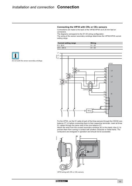
Connecting the <strong>VIP35</strong> with CRc or CEc sensors<br />
Connections are made to the back of the <strong>VIP30</strong>/<strong>VIP35</strong> via 6.35 mm fast-on<br />
connectors.<br />
The diagrams correspond to the S1-S3 wiring configuration.<br />
The wiring of the sensor secondary windings determines the <strong>VIP30</strong>/<strong>VIP35</strong> current<br />
setting range.<br />
Current setting range<br />
Wiring<br />
8 A - 80 A S1 - S2<br />
20 A - 200 A S1 - S3<br />
DE50904<br />
Do not earth the sensor secondary windings.<br />
For the <strong>VIP35</strong>, run the S1 cable of each of the three sensors through the CSH30 core<br />
balance CT (J) before connecting them to their respective terminals. Insert all three<br />
S1 cables through the same side of the core balance CT.<br />
Attach the wires from the unused secondary windings (K) to the plastic clips (L) to<br />
prevent them from coming in contact with another conductor or metal frame. The<br />
conductors are energized in operation <strong>and</strong> should not be accessible.<br />
DE50910<br />
<strong>VIP35</strong> wiring with CRc or CEc sensors.<br />
13