series 201 offset captured (2" x 4 1/2") - PRL Glass Systems Inc
series 201 offset captured (2" x 4 1/2") - PRL Glass Systems Inc
series 201 offset captured (2" x 4 1/2") - PRL Glass Systems Inc

You also want an ePaper? Increase the reach of your titles
YUMPU automatically turns print PDFs into web optimized ePapers that Google loves.
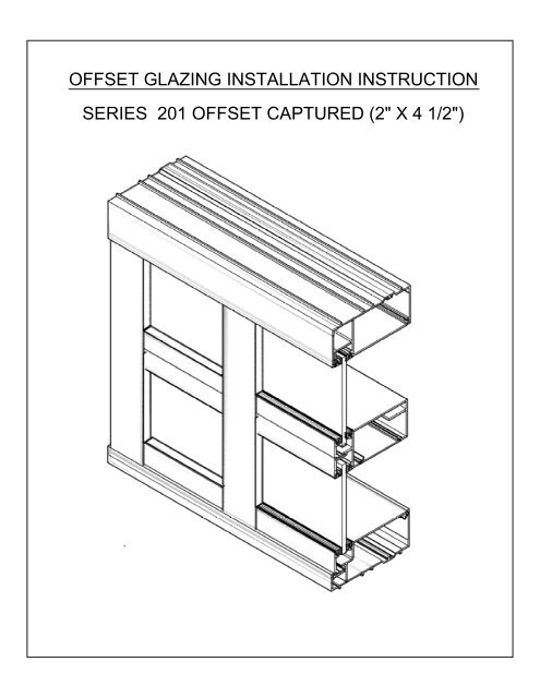
OFFSET GLAZING INSTALLATION INSTRUCTION<br />
SERIES <strong>201</strong> OFFSET CAPTURED (2" X 4 1/2")
SERIES <strong>201</strong> OFFSET SYSTEM<br />
TABLE OF CONTENTS<br />
GENERAL NOTES............................................................................Sheet 2 and 3<br />
FRAME FABRICATION ...................................................................Sheet 4 -5<br />
FRAME INSTALLATION ................................................................. Sheet 5 -8<br />
INSTALLATION INSTRUCTIONS<br />
GENERAL NOTES<br />
HANDLING, STORAGE AND PROTECTION OF ALUMINUM<br />
The following precautions are recommended to protect the material against damage.<br />
Following these precautions will help ensure early acceptance of your products and<br />
workmanship.<br />
A. HANDLE CAREFULLY<br />
All aluminum materials at job site must be stored in a safe place well removed from possible<br />
damage by other trades. Cardboard wrapped or paper interleaved materials must be<br />
kept dry.<br />
B. CHECK ARRIVING MATERIALS.<br />
Check for quantity and keep records of where various materials are stored.<br />
C. KEEP MATERIAL AWAY FROM WATER, MUD AND SPRAY.<br />
Prevent cement plaster or other materials from damaging the finish.<br />
D. PROTECT THE MATERIALS AFTER ERECTION.<br />
Protect erected frame with polyethylene or canvas splatter screen. Cement, plaster, terrazzo,<br />
other alkaline solutions and acid based materials used to clean masonry are harmful to the<br />
finish. If any of these materials come in contact with the aluminum, IMMEDIATELY remove with<br />
water and mild soap.<br />
The rapidly changing technology within the architectural aluminum products industry demands that <strong>PRL</strong> Aluminum<br />
reserve the right to revise, discontinue or change any product line, specification or electronic media without prior<br />
written notice.<br />
<strong>PRL</strong> ALUMINUM, INC.<br />
2
GENERAL INSTALLATION NOTES<br />
RECOMMENDED GUIDELINES FOR ALL INSTALLATIONS:<br />
1. REVIEW CONTRACT DOCUMENTS. Check shop drawings, installation instructions, architectural drawings and shipping<br />
lists to become thoroughly familiar with the project. The shop drawings take precedence and include specific details for<br />
the project. Note and field verified notes on the shop drawings prior to installing. The installation instructions are of<br />
general nature and cover most conditions.<br />
2. INSTALLATION. All materials are to be installed plumb, level and true.<br />
3. BENCH MARKS. All work should start from benchmarks and/or column lines as established by the architectural<br />
drawings and the general contractor with guaranteed accuracy. Working from these datum points and lines determine:<br />
a) The plane of the wall in reference to <strong>offset</strong> lines provided on each floor.<br />
b) The finish floor lines in reference to benchmarks on the outer building columns.<br />
c) Mullion spacing from both ends of masonry opening to prevent dimensional build-up of daylight opening.<br />
4. FIELD WELDING. All field welding must be adequately shielded to avoid any splatter on glass or aluminum.Results will<br />
be unsightly and/or structurally unsound. Advise general contractor and other trades accordingly. All field welds of steel<br />
anchors must receive touch-up paint (zinc chromate) to avoid rust.<br />
5. SURROUNDING CONDITIONS. Make certain that construction, which will receive your materials, is in accordance with<br />
the contract documents. If not, notify the general contractor in writing and resolve differences before proceeding with<br />
work.<br />
6. ISOLATION OF ALUMINUM. Aluminum to be placed in direct contact with uncured masonry or incompatible materials<br />
should be isolated with a heavy coat of zinc chromate or bituminous paint.<br />
7. SEALANTS. Sealants must be compatible with all materials with which they have contact, including other sealant<br />
surfaces. Consult with sealant manufacturer for recommendations relative to joint size, shelf life, compatibility,<br />
cleaning/priming, tooling, adhesion, etc. It is the responsibility of the Glazing Contractor to submit a statement from the<br />
sealant manufacturer indicating that glass and glazing material have been tested for compatibility and adhesion with<br />
glazing sealants, and interpreting test results relative to material performance, including recommendations for primers<br />
and substrate preparation required to obtain adhesion. The chemical compatibility of all glazing materials and framing<br />
sealants with each other and with like materials used in glass fabrication must be established. This is required on every<br />
project.<br />
8. FASTENING. Within the body of these instructions "fastening" means any method of securing one part to another or to<br />
adjacent materials. Only those fasteners used within the system are specified in these instructions. Due to the varying<br />
perimeter conditions and performance requirements perimeter and anchor fasteners are not specified in these<br />
instructions. For perimeter and anchor fasteners refer to the shop drawings or consult the fastener supplier.<br />
9. BUILDING CODES. Due to the diversity in state/provincial local and federal laws and codes that govern the design and<br />
application of architectural products it is the responsibility of the individual architect owner and installer to assure that<br />
products selected for use on projects comply with all the applicable building codes and laws. <strong>PRL</strong> ALUMINUM INC.<br />
exercises no control over the use or application of its products, glazing materials and operating hardware and assumes<br />
no responsibility thereof.<br />
10. EXPANSION JOINTS. Expansion joints and perimeter seals shown in these instructions and in the shop drawings are<br />
shown at normal size. Actual dimensions may vary due to perimeter conditions and/or difference in metal temperature<br />
between the time of fabrication and the time on installation. Gap between expansion members should be based on<br />
temperature at time of installation.<br />
11. WATER HOSE TEST. As soon as a representative amount of the wall has been glazed (500 square feet) a water hose<br />
test should be conducted in accordance with AAMA 501.2 specifications to check the installation. On all jobs the hose test<br />
should be repeated every 500 square feet during the glazing operation.<br />
12. COORDINATION WITH OTHER TRADES. Coordinate with the general contractor any sequence with other trades, which<br />
<strong>offset</strong> curtain wall installation (i.e. fire proofing, back-up walls, partitions, ceilings, mechanical ducts, converters etc.)<br />
13. CARE AND MAINTENANCE. Final cleaning of exposed aluminum surfaces should be done in accordance with AAMA.<br />
609.1 anodized aluminum and 610.1 for painted aluminum.<br />
<strong>PRL</strong> ALUMINUM, INC.<br />
3
OFFSET INSTALLATION INSTRUCTIONS<br />
Details in these instructions are for Series <strong>201</strong> members.<br />
Measure ROUGH OPENING minus perimeter seal joint to determine FRAME DIMENSION.<br />
Allow 1/4" minimum clearance for shimming and sealant around perimeter.<br />
FRAME FABRICATION<br />
1. Cut member to size<br />
Head and Sill channels: (Parts <strong>201</strong> HC and <strong>201</strong> SC) FRAME WIDTH<br />
Wall Jamb and Vertical: (Parts <strong>201</strong> WJ and <strong>201</strong> VM) FRAME HEIGHT minus 5/8"<br />
Head and Sill fillers : (Parts <strong>201</strong> HCF and <strong>201</strong> HM) D.L.O. -1/32"<br />
Horizontal members: (Parts <strong>201</strong> HM) D.L.O. -1/32 "<br />
Intermediate horizontal fillers: (Parts <strong>201</strong> HMF) D.L.O. -1/32"<br />
Horizontal glazing stop: (Parts <strong>201</strong> GS-H) D.L.O. -1/32"<br />
Sill channel glazing stop: (Parts <strong>201</strong> GS) D.L.O. -1/32"<br />
The "SKETCH 101" below show each horizontal members.<br />
<strong>201</strong> HC<br />
<strong>201</strong> HCF<br />
<strong>201</strong> GS-H<br />
<strong>201</strong> HMF<br />
<strong>201</strong> HM<br />
<strong>201</strong> GS<br />
<strong>201</strong> HM<br />
<strong>201</strong> SC<br />
"SKETCH 101"<br />
EXTERIOR GLAZING<br />
2. Drill 5/16" diameter weep holes in sill channel, two per lite @ 3" from vertical<br />
mullion. Weep slots may be drilled in face or bottom of sill channel.<br />
3. Mark horizontal locations on mullion and with drill jigs, drill holes for assembly<br />
screws. (See SKETCH 101)<br />
<strong>PRL</strong> ALUMINUM, INC.<br />
4
drill jig<br />
located<br />
@ top<br />
of horizontal<br />
out<br />
line of<br />
clip &<br />
horiz.<br />
top<br />
of horizontal<br />
tap drill .177 dia.<br />
for<br />
#12 screw (typ.)<br />
drill jig<br />
vertical<br />
mullion<br />
VERTICAL SECTION VERTICAL SIDE VIEW<br />
"SKETCH 101"<br />
4. Butter end of clip (251 hm-clip) w/ sealant and attach anchor clips to vertical with screws<br />
as shown. See "SKETCH 102" below.<br />
Vertical<br />
Mullion<br />
ANCHOR<br />
CLIP<br />
(PT.<br />
251 HM-CLIP)<br />
#12 X 2" P.H.S.M.S.<br />
"SKETCH 102"<br />
<strong>PRL</strong> ALUMINUM,INC.<br />
5
5. Apply end dams to head and sill channel at ends and secure with screws.<br />
Seal around and up joint to make water tight. See "Sketch 103" below.<br />
SEAL<br />
JOINERY @<br />
SILL CAN<br />
TO END<br />
DAM COMPLETELY<br />
PRIOR TO<br />
INSTALL<br />
END JAMB<br />
SILL<br />
CHANNEL<br />
SCREWS @<br />
HEAD CAN<br />
(SEAL HEAD W/<br />
SEALANT<br />
SEAL<br />
END OF<br />
SCREW W/ SEALANT<br />
END DAM<br />
SEAL JOINERY @ END<br />
DAM OF CAN W/<br />
SEALANT<br />
END<br />
DAM @<br />
HEAD CAN<br />
HEAD CHANNEL<br />
1 SILL CAN END DAM 2 HEAD CAN END DAM<br />
NOTE:<br />
Clean all surfaces prior to applying<br />
sealants. See sealant manufacturer<br />
requirements.<br />
"SKETCH 103 "<br />
FRAME<br />
INSTALLATION<br />
6. Set head and sill channels in place plumb and square; shim as required to level and<br />
anchor to structure. Locate fasteners 6" from end of channel and 24" o.c. or as require per<br />
engineer. Holes for fasteners should be slotted horizontally to allow for thermal movement and<br />
seal over fastener head with sealant. Hard anchor head and sill channel to structure<br />
at mid-point of cut lenght. Shim sill and head channel at fastener locations. See "SKETCH 105".<br />
on sheet 7. Make sure sill channel remains clean of debris during installation to prevent blockage<br />
of weep<br />
holes.<br />
Shim<br />
as required.<br />
Note: Do not shim<br />
behind<br />
end dam<br />
Head and sill fasteners<br />
NOTE:<br />
CRITICAL SEAL area<br />
Carefully seal over<br />
head of<br />
fasteners at<br />
sill only<br />
"SKETCH 104 "<br />
5. Install wall jamb into head and sill channels. Shim and plumb as required . See "Sketch 104" above.<br />
<strong>PRL</strong><br />
ALUMINUM, INC.<br />
6
8. Snap-in head and sill fillers for the first bay.<br />
HEAD<br />
CHANNEL<br />
NOTE:<br />
Seal head of fastener<br />
at head if no interior<br />
perimeter seal<br />
HORIZONTAL<br />
Anchor<br />
Clip<br />
#8 x 1/2' P.H.S.M.S<br />
SILL<br />
CHANNEL<br />
weep<br />
hole<br />
NOTE:<br />
Critical seal, carefully<br />
seal over head of<br />
fasteners @ sill only<br />
weep<br />
hole<br />
9. Install next vertical tight against head and sill fillers. Never allow two shallow pockets to<br />
face each orher. Seal joints where verticals meet head and sill members. Vertical mullion<br />
must be attached to head/sill channels when end reactions exceed 500lbs.<br />
10.Snap-in head and sill fillers for the next glass bay and repeat steps 8 and 9 until all verticals<br />
head and sill inserts are installed. At the last glass bay install jamb member in place before<br />
snapping in head and sill fillers. Note:A check should be made for every four bays for<br />
tolerances.<br />
"SKETCH 105"<br />
11.Roll horizontal over anchor clip and secure with screw provided. (See Horizontal section<br />
above)<br />
<strong>PRL</strong> ALUMINUM, INC.<br />
7
12. Apply silicone to vertical glazing pocket and gasket reglet at vertical/horizontal intersection.<br />
Silicone must be applied to two sides of pocket. Clearance at outside will allow infiltrated<br />
water to run down to subsill. See "Sketch 106" below.<br />
13. Insert water deflectors into glazing pocket and slide them down into position. See "Sketch 106"<br />
below. Top of deflector must be flush with horizontal glazing pocket.<br />
NOTE: Water deflectors applied @ door jambs must be sealed completely all around to prevent<br />
water from running to floor ( water will drain @ opposite end.)<br />
Apply silicone to<br />
both sides of glazing<br />
pocket at vertical /<br />
horizontal<br />
joint<br />
Joinary seal @<br />
vertical to sill channel<br />
Joinary seal @<br />
horizontal to vertical<br />
Completely<br />
seal around<br />
water deflector @ horizontal<br />
to vertical to make a water<br />
tight<br />
seal<br />
Joinary seal @<br />
horizontal to vertical<br />
.040 alum. water<br />
deflector set<br />
in<br />
sealant and seal<br />
joint<br />
as shown<br />
Leave open<br />
for weepage<br />
Fill gasket reglet<br />
with silicone 1" each<br />
way after water deflector<br />
is<br />
installed.<br />
Seal horizontal to<br />
vertical joint (typical)<br />
Completely seal joinary<br />
of horizontal to vertical<br />
intersection after<br />
water<br />
deflector is installed<br />
"SKETCH 106"<br />
"SKETCH 107"<br />
<strong>PRL</strong> ALUMINUM,<br />
INC.<br />
8