EFM User Manual - CTC Union Technologies Co.,Ltd.
EFM User Manual - CTC Union Technologies Co.,Ltd.
EFM User Manual - CTC Union Technologies Co.,Ltd.

You also want an ePaper? Increase the reach of your titles
YUMPU automatically turns print PDFs into web optimized ePapers that Google loves.
G.SHDSL.bis<br />
<strong>EFM</strong> Network Extender
<strong>CTC</strong> <strong>Union</strong> <strong>Technologies</strong> <strong>Co</strong>., <strong>Ltd</strong>.<br />
Far Eastern Vienna Technology Center (Neihu Technology Park)<br />
8F, No. 60 Zhouzi St.<br />
Neihu District<br />
Taipei 114<br />
Taiwan<br />
Tel: +886-2-26591021<br />
Fax: +886-2-27991355<br />
Email: info@ctcu.com<br />
URL: http://www.ctcu.com<br />
<strong>EFM</strong> Operation <strong>Manual</strong><br />
G.SHDSL.bis Ethernet in First Mile (<strong>EFM</strong>) Modem<br />
Version 0.9b Mar 2009<br />
This <strong>Manual</strong> supports the following models:<br />
<strong>EFM</strong>-10 Single pair (2 wire) Ethernet Extender<br />
<strong>EFM</strong>-20 Two pair (4 wire) Ethernet Extender<br />
<strong>EFM</strong>-40 Four pair (8 wire) Ethernet Extender<br />
<strong>Co</strong>pyright © 2008-2009, <strong>CTC</strong> <strong>Union</strong> <strong>Technologies</strong>, Inc.<br />
All rights reserved.<br />
All specifications are subject to change without prior notice.
Legal<br />
The information in this publication has been carefully checked and is believed to be entirely accurate at the time of<br />
publication. <strong>CTC</strong> <strong>Union</strong> <strong>Technologies</strong> assumes no responsibility, however, for possible errors or omissions, or for<br />
any consequences resulting from the use of the information contained herein. <strong>CTC</strong> <strong>Union</strong> <strong>Technologies</strong> reserves the<br />
right to make changes in its products or product specifications with the intent to improve function or design at any<br />
time and without notice and is not required to update this documentation to reflect such changes.<br />
<strong>CTC</strong> <strong>Union</strong> <strong>Technologies</strong> makes no warranty, representation, or guarantee regarding the suitability of its products for<br />
any particular purpose, nor does <strong>CTC</strong> <strong>Union</strong> assume any liability arising out of the application or use of any product<br />
and specifically disclaims any and all liability, including without limitation any consequential or incidental damages.<br />
<strong>CTC</strong> <strong>Union</strong> products are not designed, intended, or authorized for use in systems or applications intended to support<br />
or sustain life, or for any other application in which the failure of the product could create a situation where personal<br />
injury or death may occur. Should the Buyer purchase or use a <strong>CTC</strong> <strong>Union</strong> product for any such unintended or<br />
unauthorized application, the Buyer shall indemnify and hold <strong>CTC</strong> <strong>Union</strong> <strong>Technologies</strong> and its officers, employees,<br />
subsidiaries, affiliates, and distributors harmless against all claims, costs, damages, expenses, and reasonable<br />
attorney fees arising out of, either directly or indirectly, any claim of personal injury or death that may be associated<br />
with such unintended or unauthorized use, even if such claim alleges that <strong>CTC</strong> <strong>Union</strong> <strong>Technologies</strong> was negligent<br />
regarding the design or manufacture of said product.<br />
TRADEMARKS<br />
Microsoft is a registered trademark of Microsoft <strong>Co</strong>rp.<br />
HyperTerminal is a registered trademark of Hilgraeve Inc.<br />
WARNING:<br />
This equipment has been tested and found to comply with the limits for a Class A digital device, pursuant to Part 15<br />
of the FCC Rules. These limits are designed to provide reasonable protection against harmful interference when the<br />
equipment is operated in a commercial environment. This equipment generates, uses, and can radiate radio<br />
frequency energy and if not installed and used in accordance with the instruction manual may cause harmful<br />
interference in which case the user will be required to correct the interference at his own expense. NOTICE: (1) The<br />
changes or modifications not expressively approved by the party responsible for compliance could void the user's<br />
authority to operate the equipment. (2) Shielded interface cables and AC power cord, if any, must be used in order to<br />
comply with the emission limits.<br />
CISPR PUB.22 Class A COMPLIANCE:<br />
This device complies with EMC directive of the European <strong>Co</strong>mmunity and meets or exceeds the following technical<br />
standard. EN 55022 - Limits and Methods of Measurement of Radio Interference Characteristics of Information<br />
Technology Equipment. This device complies with CISPR Class A.<br />
CE NOTICE<br />
Marking by the symbol CE indicates compliance of this equipment to the EMC and LVD directives of the European<br />
<strong>Co</strong>mmunity. Such marking is indicative that this equipment meets or exceeds the following technical standards: EN<br />
55022:2006, Class A, EN55024:1998+A1:2001+A2:2003, and EN60950-1:2001
TABLE OF CONTENTS<br />
1 INTRODUCTION.................................................................................................................................9<br />
1.1 DESCRIPTIONS.................................................................................................................... 9<br />
1.2 FEATURES ........................................................................................................................ 10<br />
1.3 SPECIFICATIONS ............................................................................................................... 10<br />
1.4 APPLICATIONS ................................................................................................................. 12<br />
2 GETTING TO KNOW THE <strong>EFM</strong> MODEM.........................................................................................13<br />
2.1 FRONT PANEL .................................................................................................................. 13<br />
2.2 REAR PANEL .................................................................................................................... 15<br />
2.2.1 WAN Port ................................................................................................................. 15<br />
2.2.2 LAN ports and MGMT port...................................................................................... 16<br />
2.2.3 <strong>Co</strong>nsole Port............................................................................................................ 16<br />
2.2.4 Power connection .................................................................................................. 17<br />
2.2.5 Reset Button ............................................................................................................ 17<br />
2.2.6 Protective Earth (Frame Ground) terminal............................................................ 17<br />
3 CONFIGURATION USE WEB BROWSER.........................................................................................18<br />
3.1 CONFIGURATION METHOD ................................................................................................. 18<br />
3.1.1 Web configuration.................................................................................................. 18<br />
3.1.2 Serial console configuration.................................................................................. 18<br />
3.1.3 Telnet configuration................................................................................................ 18<br />
3.2 INSTALLATION .................................................................................................................. 19<br />
3.3 SETUP UP WITH WEB BROWSER ............................................................................................. 20<br />
3.4 BASIC SETUP.................................................................................................................... 21<br />
3.4.1 Operation mode and MGMT ................................................................................. 23<br />
3.4.2 DHCP server ............................................................................................................ 24<br />
3.4.3 LAN.......................................................................................................................... 26<br />
3.4.4 Review..................................................................................................................... 27<br />
3.5 ADVANCED SETUP ............................................................................................................ 28<br />
3.5.1 SHDSL.bis <strong>EFM</strong>.......................................................................................................... 28<br />
3.5.1.1 Line Type..................................................................................................................... 29<br />
3.5.1.2 Annex Type................................................................................................................. 29<br />
3.5.1.3 TCPAM Type................................................................................................................ 29<br />
3.5.1.4 Main Rate.................................................................................................................... 29<br />
3.5.1.5 SNR margin ................................................................................................................. 30<br />
3.5.1.6 Line Probe................................................................................................................... 30
3.5.2 VLAN........................................................................................................................ 31<br />
3.5.2.1 802.1Q Tag-Based VLAN ............................................................................................ 33<br />
3.5.2.2 Port-Based VLAN......................................................................................................... 36<br />
3.5.2.3 Port-based QinQ......................................................................................................... 38<br />
3.5.3 QoS.......................................................................................................................... 40<br />
3.5.3.1 Port Based Priority....................................................................................................... 41<br />
3.5.3.2 VLAN Tag Priority......................................................................................................... 43<br />
3.5.3.3 IP DSCP Priority............................................................................................................ 46<br />
3.5.4 Rate <strong>Co</strong>ntrol............................................................................................................ 49<br />
3.6 STATUS ........................................................................................................................... 50<br />
3.6.1 SHDSL .Bis <strong>EFM</strong>......................................................................................................... 50<br />
3.6.2 MGMT ...................................................................................................................... 52<br />
3.6.3 LAN.......................................................................................................................... 53<br />
3.6.4 Interface ................................................................................................................. 54<br />
3.7 ADMINISTRATION.............................................................................................................. 55<br />
3.7.1 Security ................................................................................................................... 55<br />
3.7.2 SNMP ....................................................................................................................... 58<br />
3.7.2.1 <strong>Co</strong>mmunity Pool......................................................................................................... 59<br />
3.7.2.2 Trap Host Pool ............................................................................................................. 60<br />
3.8 UTILITY............................................................................................................................ 61<br />
3.8.1 System Info.............................................................................................................. 62<br />
3.8.2 <strong>Co</strong>nfig Tool.............................................................................................................. 63<br />
3.8.3 Upgrade.................................................................................................................. 64<br />
3.8.4 Logout ..................................................................................................................... 65<br />
3.8.5 Restart ..................................................................................................................... 66<br />
4 CONFIGURATION USE SERIAL CONSOLE AND TELNET WITH MENU DRIVEN INTERFACE .....67<br />
4.1 INTRODUCTION ................................................................................................................ 67<br />
4.1.1 Login to the <strong>Co</strong>nsole Interface .............................................................................. 67<br />
4.1.2 Telnet login.............................................................................................................. 67<br />
4.1.3 Menu Driven Interface <strong>Co</strong>mmands....................................................................... 68<br />
4.1.4 Window structure.................................................................................................... 69<br />
4.2 MAIN MENU TREE............................................................................................................. 69<br />
4.2.1 Menu tree for authorized user................................................................................ 70<br />
4.2.2 Menu tree for unauthorized user ........................................................................... 71<br />
4.3 ENABLE........................................................................................................................... 72
4.4 SETUP ............................................................................................................................. 74<br />
4.4.1 SHDSL.bis ................................................................................................................. 74<br />
4.4.1.1 Mode........................................................................................................................... 74<br />
4.4.1.2 Link.............................................................................................................................. 74<br />
4.4.1.3 Annex ......................................................................................................................... 75<br />
4.4.1.4 TCPAM......................................................................................................................... 75<br />
4.4.1.5 Maximum main rate................................................................................................... 75<br />
4.4.1.6 SNR Margin ................................................................................................................. 75<br />
4.4.1.7 Line Probe................................................................................................................... 75<br />
4.4.1.8 Clear ........................................................................................................................... 75<br />
4.4.2 LAN.......................................................................................................................... 76<br />
4.4.3 VLAN........................................................................................................................ 77<br />
4.4.3.1 Mode........................................................................................................................... 77<br />
4.4.3.2 802.11Q VLAN............................................................................................................. 78<br />
4.4.3.3 Port Based VLAN......................................................................................................... 79<br />
4.4.4 QoS.......................................................................................................................... 80<br />
4.4.4.1 Mode........................................................................................................................... 80<br />
4.4.4.2 Queue weight............................................................................................................. 81<br />
4.4.4.3 Queue schedule......................................................................................................... 81<br />
4.4.4.4 Port Based Priority QoS ............................................................................................... 82<br />
4.4.4.5 VLAN Tag Priority QoS................................................................................................. 83<br />
4.4.4.6 IP DSCP Priority Qos .................................................................................................... 84<br />
4.4.4.7 List ............................................................................................................................... 84<br />
4.4.5 RATE......................................................................................................................... 85<br />
4.4.6 MGMT ...................................................................................................................... 85<br />
4.4.7 DHCP ....................................................................................................................... 86<br />
4.4.7.1 DHCP Server................................................................................................................ 86<br />
4.4.7.2 DHCP fixed Host.......................................................................................................... 87<br />
4.4.8 DNS proxy ............................................................................................................... 88<br />
4.4.9 Host name............................................................................................................... 89<br />
4.4.10 Default................................................................................................................. 89<br />
4.5 STATUS ........................................................................................................................... 90<br />
4.5.1 Shdsl.bis .................................................................................................................. 90<br />
4.5.2 Interface ................................................................................................................. 91<br />
4.6 SHOW ............................................................................................................................ 91<br />
4.7 WRITE............................................................................................................................. 92<br />
4.8 REBOOT.......................................................................................................................... 92<br />
4.9 PING.............................................................................................................................. 93
4.10 ADMINISTRATION.............................................................................................................. 94<br />
4.10.1 <strong>User</strong> Profile .......................................................................................................... 94<br />
4.10.2 Security ............................................................................................................... 95<br />
4.10.2.1 Telnet TCP port............................................................................................................ 96<br />
4.10.2.2 IP address pool........................................................................................................... 96<br />
4.10.3 SNMP ................................................................................................................... 97<br />
4.10.3.1 <strong>Co</strong>mmunity................................................................................................................. 97<br />
4.10.3.2 Trap host ..................................................................................................................... 98<br />
4.10.4 Supervisor Password and ID............................................................................... 99<br />
4.10.4.1 Supervisor Password................................................................................................... 99<br />
4.10.4.2 Supervisor ID ............................................................................................................... 99<br />
4.11 UTILITY...........................................................................................................................100<br />
4.11.1 Upgrade main software ....................................................................................101<br />
4.11.2 Backup system configuration...........................................................................101<br />
4.11.3 Restore system configuration ...........................................................................101<br />
4.12 EXIT .............................................................................................................................102<br />
5 APPENDIX – SETUP TABLE .............................................................................................................103
1 Introduction<br />
1.1 Descriptions<br />
The <strong>EFM</strong> Based Network Extender (or <strong>EFM</strong> Bridge Modem) provides a flexible and friendly<br />
solution for the Ethernet based services provision to subscribers by the service provider.<br />
Additionally, this family of products provides a simple point-to-point deployment and<br />
configuration. This allows broadband service providers to deploy single DSL lines<br />
economically when required for low density geographical areas or during start up phase.<br />
<strong>EFM</strong> Network Extender provides cost-effective symmetrical bandwidth at rates up to 22.8<br />
Mbps (for 4-pairs model) which allows service providers to deliver friendly Ethernet services<br />
rapidly. <strong>EFM</strong> Network Extender extends the reach of Ethernet services to the sites with no fiber<br />
access by using bonded copper pairs. Designed with standards-based <strong>EFM</strong> technology<br />
(2BASE-TL), the delivery of Ethernet services with <strong>EFM</strong> modem can be deployed quickly on<br />
the existing copper plant. It provides an affordable solution for point-to-point connection<br />
between remote office and enterprise headquarters.<br />
<strong>EFM</strong> Network Extender implements the management features based on IEEE 802.3ah standard<br />
and enables users to significantly reduce operational expenses by eliminating unnecessary<br />
transformation between Ethernet and legacy ATM network. Being based on user-friendly<br />
Ethernet, it saves time and costs by simplifying engineering tasks without additional training<br />
costs. The <strong>EFM</strong> architecture utilizes 100% packet transmission technology for optimum<br />
throughput and reliability. With a compact form-factor design and optimization for the use over<br />
existing copper network, <strong>EFM</strong> Network Extender reduces the initial investment cost and<br />
deployment time in delivering higher speed Ethernet service. It provides minimal risk bearing<br />
and quick return on investment to service providers and enterprises.<br />
<strong>EFM</strong> Network Extender can bond up to 4 pairs and deliver up to 22.8 Mbps Ethernet services to<br />
all users within their service area by utilizing existing copper infrastructure and <strong>EFM</strong> 802.3ah<br />
PAF bonding technology. Service providers and enterprises are able to offer symmetrical high<br />
speed connectivity for transparent Ethernet service on DSLAM backhaul or Wireless backhaul<br />
and more.<br />
<strong>EFM</strong> Network Extender provides future-proof features meeting Ethernet Quality of Service<br />
(QoS) requirements by utilizing 802.1q VLAN capabilities, four levels of priorities, traffic flow<br />
control and rate control. These traffic management and QoS features enable service providers<br />
to offer highly profitable and value-added services to a vast majority of business and<br />
institutional sites.<br />
9
1.2 Features<br />
<br />
<br />
<br />
<br />
<br />
<br />
<br />
<br />
<br />
<br />
Extend Ethernet Services to sites with existing copper infrastructure<br />
Increased Flexibility in Deployment<br />
Lower Investment and Quick Return on Investment<br />
<strong>EFM</strong> Bonding (PAF, PME Aggregation Function) up to 22.8Mbps (4 pairs)<br />
Support <strong>EFM</strong> OAM complying with IEEE 802.3ah<br />
Flexible configuration as CPE side or CO side<br />
Low Delay, Jitter and Packet Loss for delay sensitive application<br />
<strong>Co</strong>mprehensive and easy OAM & P functions in provisioning and managing<br />
QoS feature for guaranteed Ethernet service<br />
Future-proof Ethernet traffic management and QoS features<br />
1.3 Specifications<br />
WAN Interface<br />
One RJ-45 <strong>Co</strong>nnector, 8 pins<br />
SHDSL.bis: ITU-T G.991.2 (2004) Annex AF/BG<br />
Encoding scheme: 16-TCPAM, 32-TCPAM<br />
2BASE-TL, 64/65-octet encoding<br />
<strong>EFM</strong> bonding (IEEE 802.3ah PAF)<br />
Maximum date rate is 22.8Mbps for 8-wire mode (5.7Mbps/Port x 4Ports=22.8Mbps)<br />
Impedance: 135 ohms<br />
LAN Interface<br />
Four RJ-45 <strong>Co</strong>nnectors<br />
4-port switching hub<br />
10/100 Base-TX auto-sensing and auto-negotiation<br />
Auto-MDI/MDIX (Auto-Crossover)<br />
802.1d Transparent Bridging<br />
Up to 2K MAC Addresses<br />
Indicators<br />
WAN1, WAN2, WAN3 and WAN4: Link/Activity<br />
LAN1, LAN2, LAN3 and LAN4: Link/Act and 10M/100Mbps<br />
System: Power, Alarm and Management port<br />
10
VLAN Support<br />
802.1Q Tag-Based VLAN<br />
Port-Based VLAN<br />
Port-Based Q-in-Q<br />
Priority Re-mapping<br />
VLAN Trunk mode<br />
QoS Support<br />
Ingress Rate control<br />
Egress Traffic shaping<br />
Classification based on Port Base / VLAN Tag / DSCP<br />
4 Priority Queues<br />
WRR(Weighted round-robin)/ BE(Best Effort) / SP(Strictly Priority)<br />
Management Interface<br />
In-Band<br />
<strong>EFM</strong> ( IEEE 802.3ah) OAM<br />
Web Browser (HTTP), Telnet, <strong>Co</strong>nsole<br />
Out-Band<br />
Easy-to-use web-based GUI for quick setup, configuration and management<br />
Menu-driven interface for local console and Telnet access<br />
Password protected management and access control list for administration<br />
Software upgrade via web-browser or FTP server<br />
Physical/Electrical<br />
Dimensions: 19.8 x 4.8 x 16.6cm (WxHxD)<br />
Power: 100~240VAC (use external power adapter)<br />
Power consumption: 9 watts max.<br />
Temperature: 0~45˚C<br />
Humidity: 0%~95%RH (non-condensing)<br />
Memory<br />
2MB Flash Memory, 8MB SDRAM<br />
Products’ Information<br />
<strong>EFM</strong>-10 : 1 pair 2BASE-TL <strong>EFM</strong> Network Extender<br />
<strong>EFM</strong>-20 : 2 pair 2BASE-TL <strong>EFM</strong> Network Extender<br />
<strong>EFM</strong>-40 : 4 pair 2BASE-TL <strong>EFM</strong> Network Extender<br />
11
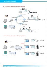
1.4 Applications<br />
<strong>EFM</strong> DSLAM to point connection<br />
Point to point connection<br />
12
2 Getting to know the <strong>EFM</strong> Modem<br />
This section will introduce the hardware of the <strong>EFM</strong> modem.<br />
2.1 Front Panel<br />
The front panel contains LED which show status of the <strong>EFM</strong> Modem.<br />
13
LED status of <strong>EFM</strong> Modem :<br />
LEDs Active Description<br />
PWR On Power on<br />
ALM<br />
On SHDSL.bis line connection is dropped<br />
Blink SHDSL.bis self test<br />
MGMT On Management port line connection is established<br />
On SHDSL.bis line 1 connection is established<br />
LINK 1<br />
SHDSL.bis line 1 handshake<br />
Blink<br />
Transmit or received data over SHDSL.bis link 1<br />
On SHDSL.bis line 2 connection is established<br />
LINK 2<br />
SHDSL.bis line 2 handshake<br />
Blink<br />
Transmit or received data over SHDSL.bis link 2<br />
WAN<br />
On SHDSL.bis line 3 connection is established<br />
LINK 3<br />
SHDSL.bis line 3 handshake<br />
Blink<br />
Transmit or received data over SHDSL.bis link 3<br />
On SHDSL.bis line 4 connection is established<br />
LINK 4<br />
SHDSL.bis line 4 handshake<br />
Blink<br />
Transmit or received data over SHDSL.bis link 4<br />
LINK/ACT1<br />
On Ethernet cable is connected to LAN 1<br />
Blink Transmit or received data over LAN 1<br />
LAN<br />
LINK/ACT2<br />
On Ethernet cable is connected to LAN 2<br />
Blink Transmit or received data over LAN 2<br />
LINK/ACT3<br />
On Ethernet cable is connected to LAN 3<br />
Blink Transmit or received data over LAN 3<br />
LINK/ACT4<br />
On Ethernet cable is connected to LAN 4<br />
Blink Transmit or received data over LAN 4<br />
100M 1<br />
On LAN 1 is on 100M mode<br />
Off LAN 1 is on 10M mode<br />
LAN<br />
100M 2<br />
On LAN 2 is on 100M mode<br />
Off LAN 2 is on 10M mode<br />
100M 3<br />
On LAN 3 is on 100M mode<br />
Off LAN 3 is on 10M mode<br />
100M 4<br />
On LAN 4 is on 100M mode<br />
Off LAN 4 is on 10M mode<br />
14
2.2 Rear Panel<br />
The rear panel of G.SHDSL.bis <strong>EFM</strong> Modem is where all of the connections are made.<br />
<strong>Co</strong>nnector<br />
DC-IN<br />
CONSOLE<br />
RST<br />
LAN (1,2,3,4)<br />
MGMT<br />
DSL<br />
Description<br />
Power adaptor inlet: Input voltage 9VDC<br />
RJ-45 (serial port) for system configuration and maintenance<br />
Reset button for reboot or load factory default<br />
10/100Base-TX nway and auto-MDIX for LAN ports (RJ-45)<br />
RJ-45 for management port<br />
G.SHDSL .Bis interface for WAN port (RJ-45)<br />
Frame Ground / Protective earth<br />
2.2.1 WAN Port<br />
The <strong>EFM</strong> modem have one port for WAN port connection, this is a G.SHDSL .Bis interface<br />
The pin assignments for SHDSL line cable are:<br />
For one pair (2-wire) model, Loop1 has been used<br />
For two pair (4-wire) model, Loop1 and 2 have been used<br />
For four pair (8-wire) model, Loop1, 2, 3 and 4 have been used<br />
15
2.2.2 LAN ports and MGMT port<br />
The <strong>EFM</strong> modem has four LAN ports and one MGMT Ethernet port. Those ports are<br />
auto-negotiating and auto-crossover. In 10/100Mbps Fast Ethernet, the speed can be 10Mbps<br />
or 100Mbps and the duplex mode can be half duplex or duplex.<br />
An auto-negotiating port can detect and adjust to the optimum Ethernet speed(10/100 Mbps)<br />
and duplex mode(full duplex or half duplex) of the connected device.<br />
The auto-crossover(auto-MDI/MDI-X) function automatically works with a straight-through or<br />
crossover Ethernet cable.<br />
2.2.3 <strong>Co</strong>nsole Port<br />
<strong>Co</strong>nnect the RJ-45 jack of the console cable to the console port of the <strong>EFM</strong> modem. <strong>Co</strong>nnect<br />
the DB-9 female end to a serial port( COM1 , COM2 or other COM port) of your computer.<br />
The wiring diagram of console cable is as followings:<br />
The pin assignment of RJ-45 modular jack of the console cable:<br />
Pin Number Abbrev. Description<br />
1 DSR DCE ready<br />
2 DCD Received Line Signal Detector<br />
3 DTR DTE ready<br />
4 GND Signal Ground<br />
5 RXD Received Data<br />
6 TXD Transmitted Data<br />
7 CTS Clear to Send<br />
8 RTS Request to Send<br />
Figure<br />
1 8<br />
Top View<br />
1 8<br />
Front View<br />
16
2.2.4 Power connection<br />
Make sure you are using the correct power source for the AC/DC adaptor. Inset the female end<br />
of power adaptor’s cord into the power receptacle on the rear panel. <strong>Co</strong>nnect the power<br />
adaptor to an appropriate AC power source.<br />
2.2.5 Reset Button<br />
The reset button can be used in one of two ways.<br />
(1) Press the Reset Button for two seconds will cause system reboot.<br />
(2) Pressing the Reset Button for eight seconds will cause the product to load the factory<br />
default settings, losing all of your set configuration. When you want to change the modem's<br />
configuration but forgot the user name or password, or if the product is having problems<br />
connecting to the Internet and you want to configure it again clearing all configurations, press<br />
the Reset Button for eight seconds with a paper clip or sharp pencil.<br />
2.2.6 Protective Earth (Frame Ground) terminal<br />
The marked lug or terminal should be connected to the building protective earth bus.<br />
The function of protective earth does not serve the purpose of providing protection against<br />
electrical shock, but instead enhances surge suppression on the DSL lines for installations<br />
where suitable bonding facilities exist.<br />
The connector type is M3 machine screw.<br />
17
3 <strong>Co</strong>nfiguration use Web Browser<br />
3.1 <strong>Co</strong>nfiguration method<br />
There are three methods to configure the <strong>EFM</strong> modem: serial console, Telnet and Web<br />
Browser. <strong>User</strong>s need to choose one method to configure the <strong>EFM</strong> modem. The easiest method<br />
is via web configuration.<br />
3.1.1 Web configuration<br />
Make sure that Ethernet Adapter had been installed in PC or laptop used for configuration of<br />
the modem. TCP/IP protocol is necessary for web configuration, so please check the TCP/IP<br />
protocol whether it has been installed.<br />
The <strong>EFM</strong> modem provides a browser interface that lets you configure and manage the <strong>EFM</strong><br />
modem. After you set up your IP address for the <strong>EFM</strong> modem. You can access the <strong>EFM</strong><br />
modem’s Web interface applications directly in your browser by entering the IP address of the<br />
<strong>EFM</strong> modem.You can then use your Web browser to list and manage configuration parameters<br />
from a PC. Web <strong>Co</strong>nfiguration requires Internet Explorer 5.0 or later or Netscape Navigator 6.0<br />
and later versions. The recommended screen resolution is 1024 by 768 pixels.<br />
3.1.2 Serial console configuration<br />
For Serial <strong>Co</strong>nsole, users can directly connecting a terminal or a PC equipped with a<br />
terminal-emulation program (such as Hyper Terminal or PuTTY) to the <strong>EFM</strong> modem’s serial<br />
console port. Use of the supplied serial cable (RJ-45 to DB9F) is required to connect the <strong>EFM</strong><br />
modem to PC. After making this connection, configure the terminal-emulation program to use<br />
the following parameters: 9600 bps , 8 data bits , no parity and 1 stop bit.<br />
3.1.3 Telnet configuration<br />
Make sure that Ethernet Adapter had been installed in PC or laptop used for configuration of<br />
the modem. Open a command window or run the command, "telnet 192.168.1.1" . The modem<br />
will ask for the user name and password for remote login when using telnet; Please use<br />
"admin" for username and "admin" for password. All display screens are the same as serial<br />
console configuration.<br />
The IP address 192.168.1.1 is the default value. You may change it to another IP for your<br />
application.<br />
18
3.2 Installation<br />
The following guide is designed to lead users through Web <strong>Co</strong>nfiguration of G.shdsl.bis <strong>EFM</strong><br />
Modem in the easiest and quickest way possible. Please follow the instructions carefully.<br />
<strong>Co</strong>nnect the power adapter to the port labeled DC 9V on the rear panel of the <strong>EFM</strong> modem.<br />
<strong>Co</strong>nnect the Ethernet cable to MGMT port.<br />
(Note: The <strong>EFM</strong> modem supports auto-MDIX so both straight through and cross-over Ethernet<br />
cables can be used.)<br />
<strong>Co</strong>nnect the phone cable to the <strong>EFM</strong> modem and the other side of phone cable to wall jack.<br />
<strong>Co</strong>nnect the power adapter to power source.<br />
Turn on the PC or NB, which will be used for configuration of the <strong>EFM</strong> modem.<br />
!<br />
To avoid possible damage to this <strong>EFM</strong> modem, do not turn on the <strong>EFM</strong> modem before<br />
Hardware Installation.<br />
<strong>Co</strong>nnection with SHDSL .Bis <strong>EFM</strong> Modem<br />
19
3.3 Setup up with Web Browser<br />
This section introduces the configuration and functions of the web-based management. This<br />
is an HTML-based management interface that allows easy <strong>EFM</strong> modem setup and monitoring.<br />
The <strong>EFM</strong> modem offers all monitoring and management features that allow users to manage<br />
this <strong>EFM</strong> modem from anywhere on the network through a standard browser such as Internet<br />
Explorer, Netscape, Mozilla or Firefox Browsers.<br />
TCP/IP setup<br />
When DHCP function is Enabled, the <strong>EFM</strong> modem acts as DHCP server on your network, the<br />
<strong>EFM</strong> modem will automatically assign IP address for PC for management port connection.<br />
For Window System, click the start button. Select setting and control panel.<br />
Double click the network icon.<br />
In the <strong>Co</strong>nfiguration window, select the TCP/IP protocol line that has been associated with<br />
your network card and then click the properties icon.<br />
Choose IP address tab and select Obtain IP address automatically and then Click the OK<br />
button.<br />
System Login<br />
<strong>User</strong> can use any browser program to connect to the <strong>EFM</strong> Modem. Type "http://" and the IP<br />
address like as "http://192.168.1.1".<br />
The default IP address and subnet mask of the management port of <strong>EFM</strong> Modem are<br />
192.168.1.1 and 255.255.255.0.<br />
If DHCP function is Disabled, your PC can set an IP on the same subnet as the modem, such<br />
as 192.168.1.X where X is from 2 to 254.<br />
Type <strong>User</strong> Name root and Password root and then click OK.<br />
The default user name and password is root. For system security, we suggest changing the<br />
password after configuration.<br />
Note: For safety, when keying in the password, star symbols will be echoed to the display.<br />
Note: After changing the <strong>User</strong> Name and Password, we strongly recommend you to save them<br />
so that the next time you login, the new <strong>User</strong> Name and Password will be used.<br />
20
The following is the index screen that displays when you first access the web interface.<br />
3.4 Basic Setup<br />
The Basic Setup contains:<br />
Operation mode and MGMT port IP<br />
DHCP server<br />
LAN<br />
<strong>User</strong> can use it to complete the basic setup of the <strong>EFM</strong> modem.<br />
21
The diagram below shows the basic setup’s flowchart.<br />
22
3.4.1 Operation mode and MGMT<br />
Click Basic for basic installation.<br />
Click CPE (Customer Premises Equipment) side or CO (Central Office) side to setup the<br />
operation mode. When connecting with <strong>EFM</strong> DSLAM, the SHDSL.bis <strong>EFM</strong> modem’s working<br />
mode should be CPE. When "LAN to LAN" connection, one side must be CO and the other<br />
side must be CPE.<br />
Enter Parameters in MGMT item.<br />
The <strong>EFM</strong> modem needs an IP address for it to be managed over the network. The factory<br />
default IP address is 192.168.1.1. The subnet mask specifies the network number portion of an<br />
IP address. The factory default subnet mask is 255.255.255.0 . You can configure another IP<br />
address in a different Subnet Mask for management purposes.<br />
IP: 192.168.1.1<br />
Subnet Mask: 255.255.255.0<br />
Host Name: SOHO<br />
Some ISPs require the Host Name be set for identification. You may check with your ISP to see<br />
if your Internet service has been configured with a host name. In most cases, this field can be<br />
ignored.<br />
Next, click Trigger DHCP service as Disable or Server. If you don’t need the DHCP service,<br />
please click Disable.<br />
23
3.4.2 DHCP server<br />
Press Next to set the next page:<br />
Dynamic Host <strong>Co</strong>nfiguration Protocol (DHCP) is a communication protocol that lets network<br />
administrators centrally manage and automate the assignment of Internet Protocol (IP)<br />
addresses in an organization's network. Using the Internet Protocol, each machine that can<br />
connect to the Internet needs a unique IP address. When an organization sets up its computer<br />
users with a connection to the Internet, an IP address must be assigned to each machine.<br />
Without DHCP, the IP address must be entered manually for each computer. If computers<br />
move to another location in another part of the network, a new IP address might need to be<br />
entered. DHCP allows a network administrator to supervise and distribute IP addresses from a<br />
central point and automatically sends a new IP address when a computer is plugged into a<br />
different place in the network.<br />
The embedded DHCP server assigns network configuration information for up to 253 users<br />
accessing the Internet at the same time.<br />
24
For example: If the LAN IP address is 192.168.0.1, the IP range of LAN is 192.168.0.2 to<br />
192.168.0.254. The DHCP server assigns the IP from Start IP Address to End IP Address. The<br />
legal IP address range is from 0 to 255, however 0 is reserved for the network name and 255 is<br />
reserved for broadcast. In usage, the legal IP address range is from 1 to 254.<br />
Lease time of 72 hours indicates that the DHCP server will reassign IP information every 72<br />
hours.<br />
The default value is 72 hours .You may set from 1 to 720 hours according to your application.<br />
Additionally, you may assign a fixed IP address for up to 10 devices while using DHCP by<br />
entering their MAC address and assigned IP into the fixed DHCP host table. Place the device’s<br />
MAC address and desired IP address in the Table of Fixed DHCP Host Entries.<br />
25
3.4.3 LAN<br />
Press Next to set the next page:<br />
Enter Parameters in LAN:<br />
LAN type item can been selected as: Disable, Dynamic IP or Static IP.<br />
Selecting either Disable and Dynamic IP will 'grey out' all the Static IP settings.<br />
If you select Static IP, you can enter the following: IP, Subnet Mask, Gateway and DNS Server’s<br />
IP.<br />
You must type the dotted decimal notation for DNS Server’s IP address<br />
The default values are as following:<br />
IP Address: 192.168.2.1<br />
Subnet Mask: 255.255.255.0<br />
Gateway: 0.0.0.0<br />
DNS Server 1: 168.95.1.1<br />
DNS Server 2: 168.95.192.1<br />
DNS Server 3:<br />
(Note: the above DNS server IP are for Hinet ISP in Taiwan. Please use your provider's DNS.)<br />
26
3.4.4 Review<br />
Press Next to set the next page:<br />
The screen will display the new configured parameters. Double check the parameters and<br />
Click Restart The <strong>EFM</strong> modem will reboot and work with the new parameters or press<br />
<strong>Co</strong>ntinue to configure other parameters.<br />
27
3.5 Advanced Setup<br />
Note: The advanced functions are only for advanced users to setup advanced functions. The<br />
incorrect setting of advanced function will affect the performance or cause system error, even<br />
disconnection.<br />
Advanced setup contains SHDSL.bis <strong>EFM</strong>, VLAN, QoS and Rate <strong>Co</strong>ntrol parameters.<br />
3.5.1 SHDSL.bis <strong>EFM</strong><br />
You can setup the Link (number of wires), Annex type, TCPAM type, Main Rate, Sub Rate and<br />
SNR margin for SHDSL.bis <strong>EFM</strong> parameters.<br />
Click SHDSL.bis <strong>EFM</strong><br />
28
3.5.1.1 Line Type<br />
Line type indicates how many wires you want to use for the SHDSL.bis connection.<br />
Line Type<br />
<strong>EFM</strong> Modem<br />
2-wire 4-wire 8-wire<br />
2-wire model ●<br />
4-wire model ● ●<br />
8-wire model ● ● ●<br />
For example, 8-wire model can select 2-wire, 4-wire or 8-wire line type.<br />
3.5.1.2 Annex Type<br />
There are two Annex types: Annex AF and Annex BG in SHDSL.bis . Check with your ISP if you<br />
are connecting a CPE to their DSLAM. Annex type must match between CO and CPE devices.<br />
3.5.1.3 TCPAM Type<br />
The default option is Auto. You may assign the different type manually by click the caption<br />
TPCAM-16 or TPCAM-32 .<br />
3.5.1.4 Main Rate<br />
You can setup the SHDSL.bis main rate is in the multiple of 64kbps , 128kpbs or 256 kpbs<br />
according using which model.<br />
Main Rate (Unit: kbps)<br />
SHDSL.bis<br />
TCPAM-16 TCPAM-32<br />
multiple<br />
<strong>EFM</strong> Modem<br />
N=3~60 N=12~89<br />
2-wire model 64 192 ~ 3840 768 ~ 5696<br />
4-wire model 128 384 ~ 7680 1536 ~ 11392<br />
8-wire model 256 768 ~ 15360 3072 ~ 22784<br />
29
3.5.1.5 SNR margin<br />
SNR margin is an index of line connection quality. You can see the actual SNR margin in<br />
STATUS SHDSL.bis. The larger is SNR margin; the better is the line connection quality.<br />
For example, if you set SNR margin in the field to 5, the SHDSL.bis connection will drop and<br />
reconnect when the SNR margin is lower than 5. The device will reduce the line rate and<br />
reconnect for better line connection quality.<br />
The range of SNR margin setting are -10 to 21.<br />
3.5.1.6 Line Probe<br />
For adaptive mode, you can setup the Line Probe to Enable. The <strong>EFM</strong> modem will adapt the<br />
data rate according to the line status. If you want to set a fixed rate, set to Disable.<br />
The screen will prompt the parameters that will be written in NVRAM. Check the parameters<br />
before writing in NVRAM.<br />
Press Restart to restart the <strong>EFM</strong> modem working with new parameters or press continue to<br />
setup other parameter.<br />
30
3.5.2 VLAN<br />
Click VLAN to configure VLAN.<br />
VLAN (Virtual Local Area Network) allows a physical network to be partitioned into multiple<br />
logical networks. Devices on a logical network belong to one group. A device can belong to<br />
more than one group. With VLAN, a device cannot directly talk to or hear devices that are not<br />
in the same group.<br />
With MTU (Multi-Tenant Unit) applications, VLAN is vital in providing isolation and security<br />
among subscribers. When properly configured, VLAN prevents one subscriber from<br />
accessing the network resources of another on the same LAN.<br />
VLAN also increases network performance by limiting broadcasts to a smaller and more<br />
manageable logical broadcast domain. In traditional switched environments, all broadcast<br />
packets go to each and every individual port. With VLAN, all broadcasts are confined to a<br />
specific broadcast domain.<br />
<strong>User</strong> can choose two types of VLAN: 802.1Q Tag-Based VLAN and Port-Based VLAN.<br />
The VLAN Setup screen changes depending on whether you choose 802.1Q Tag-Based VLAN<br />
type or Port Based VLAN type in this screen.<br />
The IEEE 802.1Q defines the operation of VLAN bridges that permit the definition, operation,<br />
and administration of VLAN topologies within a bridged LAN infrastructure.<br />
31
3.5.2.1 802.1Q Tag-Based VLAN<br />
Click the 802.1Q Tag-Based VLAN to configure the <strong>EFM</strong> modem.<br />
VID: (Virtual LAN ID) is an identification number or ID which numbers from 1 to 4094.<br />
PVID: (Port VID) is an untagged member from 1 to 4094 of default VLAN.<br />
Link Type: Access means the port can receive or send untagged packets.<br />
Trunk means that the port can only receive or send tagged packets.<br />
33
TCI (Tag <strong>Co</strong>ntrol Information field) including user priority, Canonical format indicator (CFI) and<br />
VLAN ID.<br />
TPID- defined value of 8100 in hex. When a frame has the EtherType equal to 8100, this frame<br />
carries the tag IEEE 802.1Q / 802.1P.<br />
<strong>User</strong> Priority- Defines user priority, giving eight (2 3 = 8) priority levels. IEEE 802.1P defines the<br />
operation for these 3 user priority bits.(Refer to following table)<br />
CFI (Canonical Format Indicator) is always set to zero for Ethernet switches. CFI is used for<br />
compatibility reasons between Ethernet type network and Token Ring type networks. If a<br />
frame received at an Ethernet port has a CFI set to 1, then that frame should not be forwarded<br />
as it is to an untagged port.<br />
VID- VLAN ID is the identification of the VLAN, which is basically used by the standard 802.1Q.<br />
It has 12 bits and allow the identification of 4096 (2 12 ) VLANs. Of the 4096 possible VIDs, a VID<br />
of 0 is used to identify priority frames and value 4095 (FFF) is reserved, so the maximum<br />
possible VLAN configurations are 4,094.<br />
The <strong>EFM</strong> modem by default initially configures one VLAN, VID=1.<br />
A port such as LAN1 to 4, DSL or sniffing can have only one PVID, but can have as many VID<br />
as the <strong>EFM</strong> modem has memory in its VLAN table to store them.<br />
Ports in the same VLAN group share the same frame broadcast domain and thus increase<br />
network performance through reduced boardcast traffic. VLAN groups can be modified at any<br />
time by adding, moving or changing ports without any re-cabling.<br />
34
Before enabling VLANs for the <strong>EFM</strong> modem, you must first assign each port to the VLAN<br />
group(s) in which it will participate. By default all ports are assigned to VLAN1 as untagged<br />
ports. Add a port as a tagged port if you want it to carry traffic for one or more VLANs, and any<br />
intermediate network devices or the host at the other end of the connection supports VLANs.<br />
Then assign ports on the other VLAN-aware network devices along the path that will carry this<br />
traffic to the same VLAN(s), either manually or dynamically using GVRP. However, if you want<br />
a port on this <strong>EFM</strong> modem to participate in one or more VLANs, but none of the intermediate<br />
network devices nor the host at the other end of the connection supports VLANs, then you<br />
should add this port to the VLAN as an untagged port.<br />
Note: VLAN-tagged frames can pass through VLAN-aware or VLAN-unaware network<br />
Inter-connection devices, but the VLAN tags should be stripped off before passing it on to any<br />
end-node host that does not support VLAN tagging.<br />
VLAN Classification – When the <strong>EFM</strong> modem receives a frame, it classifies the frame in one of<br />
two ways. If the frame is untagged, the <strong>EFM</strong> modem assigns the frame to an associated VLAN<br />
(based on the default VLAN ID of the receiving port). But if the frame is tagged, the <strong>EFM</strong><br />
modem uses the tagged VLAN ID to identify the port broadcast domain of the frame.<br />
Port Overlapping – Port overlapping can be used to allow access to commonly shared network<br />
resources among different VLAN groups, such as file servers or printers.<br />
Untagged VLANs – Untagged (or static) VLANs are typically used to reduce broadcast traffic<br />
and to increase security. A group of network users assigned to a VLAN form a broadcast<br />
domain that is separate from other VLANs configured on the <strong>EFM</strong> modem. Packets are<br />
forwarded only between ports that are designated for the same VLAN. Untagged VLANs can<br />
be used to manually isolate user groups or subnets.<br />
PVID - VLAN ID assigned to untagged frames received on the interface. (Default: 1)<br />
If an interface is not a member of VLAN 1 and you assign its PVID to this VLAN, the interface<br />
will automatically be added to VLAN 1 as an untagged member. For all other VLANs, an<br />
interface must first be configured as an untagged member before you can assign its PVID to<br />
that group.<br />
Link Type - Sets the port to accept the frame types: "Access" means the port can only receive<br />
or send untagged frame types. "Trunk" means that the port can only receive or send tagged<br />
frame types.<br />
35
3.5.2.2 Port-Based VLAN<br />
Click Port-Based VLAN to configure the <strong>EFM</strong> modem.<br />
Port-Based VLANs are VLANs where the packet forwarding decision is based on the<br />
destination MAC address and its associated port. When using the port-based VLAN, the port is<br />
assigned to a specific VLAN independent of the user or system attached to the port. This<br />
means all users attached to the port should be members in the same VLAN. The network<br />
administrator typically performs the VLAN assignment. The port configuration is static and<br />
cannot be automatically changed to another VLAN without manual reconfiguration.<br />
As with other VLAN approaches, the packets forwarded using this method do not leak into<br />
other VLAN domains on the network. After a port has been assigned to a VLAN, the port<br />
cannot send to or receive from devices in another VLAN.<br />
For example,<br />
36
The default setting is all ports connected which means all ports can communicate with each<br />
other. That is, there are no virtual LANs. The option is the most flexible but the least secure.<br />
If you click the LAN1 to LAN4 only with DSL and Sniffing, there are port isolation means that<br />
each LANs port can only communicate with management port and cannot communicate with<br />
each other. This option is the most limiting but also the most secure.<br />
37
3.5.2.3 Port-based QinQ<br />
Click Port-Based QinQ to configure the <strong>EFM</strong> modem.<br />
PVID (Port VID): It is an untagged member from 1 to 4094 of default VLAN.<br />
TPID (Tag protocol identifier): 33024 for IEEE802.1Q<br />
Link Type:<br />
Access means the port can receive or send untagged packets.<br />
Trunk means that the port can receive or send tagged packets.<br />
A VLAN tag uses the tag protocol identifier (TPID) field to identify the protocol type of the tag.<br />
The value of this field, as defined in IEEE 802.1Q, is 0x8100 (33024).<br />
VLAN Tag structure of an Ethernet frame<br />
38
On devices of different vendors, the TPID of the outer VLAN tag of QinQ frames may have<br />
different default values. You can set or modify this TPID value, so that the QinQ frames, when<br />
arriving at the public network, carries the TPID value of a specific vendor to allow<br />
interoperation with devices of that vendor.<br />
The TPID in an Ethernet frame has the same position with the protocol type field in a frame<br />
without a VLAN tag. To avoid chaotic packet forwarding and receiving, you cannot set the<br />
TPID value to any of the values in the table below.<br />
Reserved protocol type values:<br />
Protocol type Value<br />
ARP<br />
0x0806<br />
PUP<br />
0x0200<br />
RARP<br />
0x8035<br />
IP<br />
0x0800<br />
IPv6<br />
0x86DD<br />
PPPoE<br />
0x8863/0x8864<br />
MPLS<br />
0x8847/0x8848<br />
IPX/SPX 0x8137<br />
IS-IS<br />
0x8000<br />
LACP<br />
0x8809<br />
802.1x 0x888E<br />
Cluster<br />
0x88A7<br />
Reserved 0xFFFD/0xFFFE/0xFFFF<br />
39
3.5.3 QoS<br />
QoS (Quality of Service) refers to both a network’s ability to deliver data with minimum delay,<br />
and the networking methods used to control the use of bandwidth. Without QoS, all traffic data<br />
is equally likely to be dropped when the network is congested. This can cause a reduction in<br />
network performance and make the network inadequate for time-critical application such as<br />
video-on-demand.<br />
Click QoS to configure QoS<br />
QoS (Quality of Service) works to decide which PCs can get the priorities to pass though <strong>EFM</strong><br />
modem once if the bandwidth is exhausted or fully saturated.<br />
The priority modes have three types: Port Based Priority, VLAN Tag Priority and IP DSCP<br />
Priority. You can also Disable the QoS function.<br />
40
3.5.3.1 Port Based Priority<br />
When you click Port Based Priority, it will show the following:<br />
Select the ports to which the rule should be applied.<br />
These six ports can be applied: LAN1, LAN2, LAN3, LAN4, DSL and Sniffing<br />
The Scheduling <strong>Co</strong>nfiguration item can setup the queue type from type 0 to type 3. Each<br />
queue type can set the queue weight from 1 to 15.<br />
The Queuing method is to configure queuing algorithms for outgoing traffic. Queuing<br />
algorithms allow <strong>EFM</strong> modem to maintain separate queues for packets from each individual<br />
source or flow and prevent a source from monopolizing the bandwidth.<br />
The queuing algorithms:<br />
WRR Weight Round Robin<br />
BE<br />
SP<br />
Best Effort<br />
Strictly Priority<br />
SP (Strictly Priority) services queues based on priority only. As traffic comes into the <strong>EFM</strong><br />
modem, traffic on the highest priority queue, Q3 is transmitted first. When that queue empties,<br />
traffic on the next highest-priority queue, Q2 transmitted until Q2 empties, and then traffic is<br />
transmitted on Q1 and so on. If higher priority queues never empty, then traffic on lower<br />
priority never gets sent. The SP class is typically for video applications that require a fixed<br />
amount of bandwidth to be considered good quality.<br />
41
BE (Best Effort) is used for data applications or any non-classified traffic. This would include<br />
e-mail, Internet browsing, data back-up etc. The BE class is for traffic that can afford to wait<br />
and not affect the overall outcome of the data application.<br />
WRR (Weight Round Robin) services on a rotating basis and is activated only when a port has<br />
more traffic than it can handle. A queue is a given an amount of bandwidth irrespective of the<br />
incoming traffic on that port. The queue then moves to the back of the list. The next queue is<br />
given an equal amount of bandwidth, and then moves to the end of the list, and so on,<br />
depending on the number of queues being used. This works in a looping fashion until a queue<br />
is empty.<br />
42
3.5.3.2 VLAN Tag Priority<br />
When you click VLAN Tag Priority, it will show the following:<br />
VLAN Tag Priority uses the tag field information which has been inserted into an Ethernet<br />
frame. If a port has an 802.1Q-compliant device attached (such as this modem), these tagged<br />
frames can carry VLAN membership information.<br />
IEEE 802.1Q Tagged Frame for Ethernet:<br />
<strong>User</strong> priority is giving eight ( 2 3 = 8 ) priority levels. The default value is 0, indicating normal<br />
treatment.<br />
43
Priority Level Traffic Type<br />
0 (default) Best Effort<br />
1 Background<br />
2 Spare<br />
3 Excellent Effort<br />
4 <strong>Co</strong>ntrolled Load<br />
5 Video, less than 100 milliseconds latency and jitter<br />
6 Voice, less than 10 milliseconds latency and jitter<br />
7 Network <strong>Co</strong>ntrol<br />
Each Priority level can be set queue from 0 to 3. Scheduling <strong>Co</strong>nfiguration item can setup the<br />
type is from 1 to 3. Queue from 0 to 3 can set up their Queue Weight from 1 to 15.<br />
[Example on using type1 (WRR) Scheduling <strong>Co</strong>nfiguration]<br />
For example, you can set the <strong>EFM</strong> modem to use Weighted Round-Robin (WRR) queuing that<br />
specifies a relative weight of each queue. WRR uses a predefined relative weight for each<br />
queue that determines the percentage of service time to services each queue before moving<br />
on to the next queue. This prevents the head-of-line blocking that can occur with strict priority<br />
queuing.<br />
On the table of scheduling <strong>Co</strong>nfiguration:<br />
Queue 0 1 2 3<br />
Type 1 WRR WRR WRR WRR<br />
Weight 1 2 4 8<br />
Setup the Weighted Round-Robin (Type 1) shares bandwidth by using scheduling weights 1, 2,<br />
4 and 8 for queues 0 through 3 respectively.<br />
VLAN Tag Priority:<br />
Priority 0 1 2 3 4 5 6 7<br />
Queue 1 0 0 1 2 2 3 3<br />
44
According to the previous two tables, we can get the mapping QoS values to Egress Queues<br />
as the following:<br />
Queue 0 1 2 3<br />
Priority 1,2 0,3 4,5 6,7<br />
1,2 Queue 0<br />
0,3 Queue 1<br />
4,5 Queue 2<br />
6,7 Queue 3<br />
Serviced by weighted round robin (WRR)<br />
45
3.5.3.3 IP DSCP Priority<br />
Differentiated Services (DiffServ) is a class of service (<strong>Co</strong>S) model that enhances best-effort<br />
Internet services by differentiating traffic by users, service requirements and other criteria.<br />
Packet are specifically marked, allowing network nodes to provide different levels of service,<br />
as appropriate for video playback, voice calls or other delay-sensitive applications, via priority<br />
queuing or bandwidth allocation.<br />
DiffServ defines a new DS (Differentiated Services) field to replace the Type of Service (ToS)<br />
field in the IP header. The DS field contains a 2-bits unused field and 6-bits DSCP field which<br />
can define up to 64 service levels.<br />
The following figure illustrates the DS field:<br />
The DSCP value is used to identify 64 levels (2 6 =64) of service and determines the forwarding<br />
behavior that each packet gets across the DiffServ network. Based on the marking rule,<br />
different kinds of traffic can be marked for different priorities of forwarding. Resources can<br />
then be allocated according to the DSCP values and the configured policies.<br />
46
The following is an illustration about how the bits are used in DSCP field.<br />
Bit 0 Bit 1 Bit 2 Precedence Usage<br />
1 1 1 7 Stays the same(link layer and routing protocol keep alive)<br />
1 1 0 6 Stays the same(used for IP routing Protocols)<br />
1 0 1 5 Express Forwarding (EF)<br />
1 0 0 4 Class 4<br />
0 1 1 3 Class 3<br />
0 1 0 2 Class 2<br />
0 0 1 1 Class 1<br />
0 0 0 0 Best effort<br />
Bit 3 Bit 4 Bit 5 Usage Meaning<br />
0 -- -- Delay Normal<br />
1 -- -- Delay Low<br />
-- 0 -- Throughput Normal<br />
-- 1 -- Throughput High<br />
-- -- 0 Reliability Normal<br />
-- -- 1 Reliability High<br />
The standardized DiffServ field of the packet is marked with a value so that the packet receives<br />
a particular forwarding treatment at each network node. RFC 2597 defines the assured<br />
forwarding (AF) classes. There are four AF classes, AF1x through AF4x. Within each class,<br />
there are three drop probabilities. Depending on a given network's policy, packets can be<br />
selected for a PHB based on required throughput, delay, jitter, loss, or according to priority of<br />
access to network services.<br />
Classes 1 through 4 are referred to as AF classes.<br />
The following table illustrates the DSCP coding for specifying the AF class with the probability.<br />
Bits 0, 1, and 2 define the class; bits 3 and 4 specify the drop probability; bit 5 is always 0.<br />
Class 1 Class 2 Class 3 Class 4<br />
Low Drop<br />
Medium Drop<br />
High Drop<br />
001010<br />
AF11<br />
DSCP 10<br />
001100<br />
AF12<br />
DSCP 12<br />
001110<br />
AF13<br />
DSCP 14<br />
010010<br />
AF21<br />
DSCP 18<br />
010100<br />
AF22<br />
DSCP 20<br />
010110<br />
AF23<br />
DSCP 22<br />
011010<br />
AF31<br />
DSCP 26<br />
011100<br />
AF32<br />
DSCP 28<br />
011110<br />
AF33<br />
DSCP 30<br />
100010<br />
AF41<br />
DSCP 34<br />
100100<br />
AF42<br />
DSCP 36<br />
100110<br />
AF43<br />
DSCP 38<br />
47
When you click IP DSCP(Differentiated Services <strong>Co</strong>de Point) Priority, it will show the following:<br />
Each DSCP value (from 0 to 63) is mapped to a Queue value (from 0 to 3) from the drop-down<br />
list box. The number 0 represents the lowest priority and number 3 represents the highest<br />
priority and according various queuing strategies to tailor performance to requirements. You<br />
can easily change the table setting. If you want to save the changes, click Finish.<br />
When click finish, there will be a QoS parameters review page for your confirmation.<br />
To let the configuration that you have changed take effect, click Restart to reboot system.<br />
If you want to continue the setup procedure, click <strong>Co</strong>ntinue is O.K.<br />
48
3.5.4 Rate <strong>Co</strong>ntrol<br />
Click Rate <strong>Co</strong>ntrol to configure the <strong>EFM</strong> modem.<br />
Limiting bandwidth to specific users and ports helps control network congestion, ensure high<br />
performance, create efficient networks, and prevent a small number of users from<br />
monopolizing network bandwidth.<br />
Rate control can be used to intelligently manage bandwidth allocation in the networking. It can<br />
prevent one user or device from dominating the available network bandwidth, and it allows IT<br />
managers to allocate greater bandwidth to the departments and applications that need it.<br />
You can setup the date rate limits on each port. The date rates are: No limit, 128K, 256K, 512K,<br />
1M and 2M. The default setting is No limit on each port.<br />
49
3.6 Status<br />
When you click STATUS You can monitor the following : SHDSL.bis <strong>EFM</strong>, MGMT, LAN and<br />
INTERFACE<br />
3.6.1 SHDSL .Bis <strong>EFM</strong><br />
SHDSL.bis status including run-time device status : mode and Bitrate and Performance<br />
information: SNR margin, atteunation and CRC error count.<br />
4-pairs model (8 wire model)will showed as follows, you can know all four channel run-time<br />
status (from channel A to D).<br />
Below display screen is from four pair (8 wire) model:<br />
50
The below display screen is from a one pair (2 wire) model:<br />
If two <strong>EFM</strong> modems have been linked together, you can see their run-time line rate status and<br />
performance information from this screen.<br />
Note: CPE side’s line rate is according to the setting of CO side.<br />
If you want to clear the performance data for ERC Error <strong>Co</strong>unt, click Clear CRC Error button.<br />
51
3.6.2 MGMT<br />
MGMT status will display the MGMT interface information.<br />
You can view the general status of MGMT interface and DHCP client table.<br />
52
3.6.3 LAN<br />
LAN status will display the settings of IP type, IP address and Subnet mask.<br />
For example, this shows the IP type of LAN interface is Fixed:<br />
53
3.6.4 Interface<br />
INTERFACE status includes MGMT and LAN statistics information.<br />
Octet is a group of 8 bits, often referred to as a byte.<br />
Packet is a formatted block of data carried by a packet mode computer networks, often<br />
referred to as an Ethernet or IP packet.<br />
InOctets The field shows the number of received bytes on this port<br />
InPactets The field shows the number of received packets on this port<br />
OutOctets The field shows the number of transmitted bytes on this port<br />
OutPactets The field shows the number of transmitted packets on this port<br />
InDiscards The field shows the discarded number of received packets on this port<br />
OutDiscards The field shows the discarded number of transmitted packets on this port<br />
54
3.7 Administration<br />
This session introduces Administration including SECURITY and SNMP (Simple Network<br />
Management Protocol).<br />
3.7.1 Security<br />
For system security, we suggest changing the default user name and password in the first<br />
setup otherwise unauthorized persons can access the <strong>EFM</strong> modem and change the<br />
parameters.<br />
Press Security to setup the parameters.<br />
55
For better security, change the Supervisor ID and Supervisor password for the <strong>EFM</strong> modem. If<br />
you don’t set them, all users can be able to access the <strong>EFM</strong> modem using the default<br />
Supervisor ID and Supervisor Password "root".<br />
You can authorize five legal users to access the <strong>EFM</strong> modem via telnet or console only.<br />
The default user name and password is "admin".<br />
There are two UI modes, menu driven mode and command mode to configure the <strong>EFM</strong> modem.<br />
The menu mode uses a menu driven interface while command mode uses line commands. We<br />
will not discuss command mode in this manual.<br />
Telnet <strong>Co</strong>nsole mode:<br />
<strong>User</strong> name<br />
Password<br />
Supervisor Password<br />
All function can use<br />
Can only use ping test, view the status and configuration<br />
Exit<br />
Web Brower mode:<br />
Supervisor ID<br />
Supervisor Password<br />
All function can use<br />
Logout<br />
There is a Telnet Port number setting. The default value is 23.<br />
56
Legal address pool will setup the legal IP addresses from which authorized persons can<br />
configure the <strong>EFM</strong> modem. This is the most secure method for network administrators to<br />
setup the authorized configuration administrators by allowing only preset IP source<br />
addresses of trusted hosts.<br />
<strong>Co</strong>nfigured as 0.0.0.0 will allow all hosts on Internet or LAN to access the <strong>EFM</strong> modem.<br />
Leaving blank the trust host list will cause blocking of all PC from WAN to access the <strong>EFM</strong><br />
modem. In this case, only PC in LAN can access the <strong>EFM</strong> modem. If you type the exact IP<br />
address in the field, only that host can access the <strong>EFM</strong> modem.<br />
Click Finish to complete the setting.<br />
The browser will display the configured parameters for review. Check and confirm before<br />
writing into NVRAM.<br />
Press Restart to restart the <strong>EFM</strong> modem working with the new parameters or press <strong>Co</strong>ntinue<br />
to setup other parameters.<br />
57
3.7.2 SNMP<br />
Simple Network Management Protocol (SNMP) provides for the exchange of messages<br />
between a network management client and a network management agent for remote<br />
management of network nodes. These messages contain requests to get and set variables<br />
that exist in network nodes in order to obtain statistics, set configuration parameters, and<br />
monitor network events. SNMP communications can occur over the LAN or WAN connection.<br />
The <strong>EFM</strong> modem can generate SNMP traps to indicate alarm conditions, and it relies on SNMP<br />
community strings to implement SNMP security.<br />
This <strong>EFM</strong> modem supports both standard MIB I and MIB II.<br />
Click SNMP to configure the parameters.<br />
58
3.7.2.1 <strong>Co</strong>mmunity Pool<br />
To enable the delimitation of management domains, SNMP uses "communities". Each<br />
community is identified by a name, which is an alphanumeric string of up to 255 characters<br />
defined by the user. Any SNMP entity (this term includes both managed nodes and<br />
management stations) is assigned by its user a community name. In parallel, the user defines<br />
for each SNMP entity a list of the communities which are authorized to communicate with it,<br />
and the access rights associated with each community (this is the SNMP community name<br />
table of the entity).<br />
SNMP default communities are:<br />
Access Right<br />
Read<br />
Write<br />
<strong>Co</strong>mmunity<br />
public<br />
private<br />
Press Modify to set up community pool.<br />
In the table of current community pool, you can setup the access authority.<br />
Status: Enable turns on the SNMP function<br />
Disable turns off the SNMP function<br />
Access Right: Deny deny all access<br />
Read access read only<br />
Write access read and write.<br />
<strong>Co</strong>mmunity: This text string serves as password for access right.<br />
(note: community strings are case sensitive)<br />
After configuring the community pool, press Finish.<br />
The browser will display the configured parameters. <strong>Co</strong>nfirm them before writing into NVRAM.<br />
Press Restart to restart the <strong>EFM</strong> modem working with the new parameters or press <strong>Co</strong>ntinue<br />
to setup other parameters.<br />
59
3.7.2.2 Trap Host Pool<br />
In the table of current trap host pool, you may also setup the trap host. SNMP trap is an<br />
unsolicited informational message sent from an SNMP agent to a manager. The management<br />
station (SNMP application) receives traps. The trap host pool is the list of managers to which<br />
traps will be sent. If no trap host pool is defined, no traps are sent.<br />
Press Modify to set up trap host pool.<br />
Version: select version for trap host. (Version 1 is for SNMPv1; Version 2 for SNMPv2).<br />
Disable turns off trap generation<br />
IP Address: type in the trap host IP address<br />
<strong>Co</strong>mmunity: type in the community password.<br />
Press OK to finish the setup.<br />
The browser will display the configured parameters. Double check them before writing into<br />
NVRAM.<br />
Press Restart to restart the <strong>EFM</strong> modem working with the new parameters or press <strong>Co</strong>ntinue<br />
to setup other parameters.<br />
60
3.8 Utility<br />
This section will describe the UTILITY of the <strong>EFM</strong> modem.<br />
The UTILITY menu including:<br />
SYSTEM INFO: system information, such a hardware and firmware version<br />
CONFIG TOOL: load the factory default configuration<br />
UPGRADE: upgrade the firmware<br />
LOGOUT: logout of the system<br />
RESTART: restart the <strong>EFM</strong> modem.<br />
61
3.8.1 System Info<br />
For review the system information, click SYSTEM INFO.<br />
You can check the MCSV, Software Version, Chipset, Firmware Version, Host Name and<br />
System Up Time.<br />
MCSV This is the Manufacture's <strong>Co</strong>ncurrent Software Version and indicates the version at<br />
time of manufacturing. It will never change during the life of this modem.<br />
Software Version This is the current version of the modem. If it matches the MCSV, then the<br />
modem has never been updated.<br />
Chipset This is our internal reference to identify the hardware chipset.<br />
Firmware Version This indicates firmware version running in the chipset and is written by the<br />
chipset vendor.<br />
Host Name This value may be changed by the administrator, but the default is 'SOHO'.<br />
System Up Time This lets you know how long the <strong>EFM</strong> modem has been booted up.<br />
(Note: Reading the Software Version) Here is an example of how to report the software<br />
version in the event you wish to check for any updates or if you are requested to provide the<br />
software version to any of our support personell.<br />
1608-0000-10613C79<br />
S/W Version (1.06)<br />
Product <strong>Co</strong>de<br />
62
3.8.2 <strong>Co</strong>nfig Tool<br />
The configuration tool has three functions: load Factory Default, Restore <strong>Co</strong>nfiguration, and<br />
Backup <strong>Co</strong>nfiguration. Press CONFIG TOOL:<br />
Choose the function and then press Finish.<br />
Load Factory Default: This will load the factory default parameters to the <strong>EFM</strong> modem.<br />
Note: This action will change all of the settings to factory default. You will lose all the<br />
existing configured parameters. Default user and password are also restored.<br />
Restore <strong>Co</strong>nfiguration:<br />
In case of any configuration crash, this will help you to restore a previously backed up<br />
configuration.<br />
Click Finish after selecting Restore <strong>Co</strong>nfiguration.<br />
Browse to the backup file then press finish. The <strong>EFM</strong> modem will automatically restore the<br />
saved configuration.<br />
Backup <strong>Co</strong>nfiguration:<br />
After configuration, we suggest using this function to backup your <strong>EFM</strong> modem parameters to<br />
a configuration file on the PC. Select the Backup <strong>Co</strong>nfiguration and then press Finish. Browse<br />
to the location to save the backup file. Press Finish. The <strong>EFM</strong> modem will automatically<br />
backup the configuration. Use this file to do any required restore operation<br />
63
3.8.3 Upgrade<br />
You can upgrade the firmware of <strong>EFM</strong> modem using the upgrade function.<br />
Press Upgrade under the UTILITY menu.<br />
Type the path and file name of the firmware file you wish to upload to the <strong>EFM</strong> modem in the<br />
text box or click Browse to locate it on the PC. Press OK button to upgrade. The system will<br />
reboot automatically after finishing. (Firmware upgrades are only applied after a reboot.)<br />
After the firmware upgrade process is complete, you can see the SYSTEM INFO screen to<br />
verify your current firmware version number.<br />
64
3.8.4 Logout<br />
To exit the web configurator, press LOGOUT. You have to log in with your password again after<br />
you log out. This is recommended after you finish a management session for security<br />
reasons.<br />
65
3.8.5 Restart<br />
To restart (soft reset) the <strong>EFM</strong> modem, press Restart .<br />
When you press Restart, display screen is as following:<br />
Shown is the configuration successful save message. When the system has rebooted, you<br />
can re-open the browser.<br />
66
4 <strong>Co</strong>nfiguration use Serial <strong>Co</strong>nsole and Telnet with Menu<br />
Driven Interface<br />
4.1 Introduction<br />
4.1.1 Login to the <strong>Co</strong>nsole Interface<br />
The console port is a RJ-45 connector that enables a connection to a PC for monitoring and<br />
configuring the <strong>EFM</strong> modem. Use the supplied serial cable with a female DB-9 connector to<br />
serial port of PC and RJ-45 module jack connector to <strong>EFM</strong> modem’s console port. Start your<br />
terminal access program by terminal emulation program or Hyper Terminal and configure its<br />
communication parameters to match the following default characteristics of the console port:<br />
Parameter<br />
Value<br />
Baud rate 9600<br />
Data Bits 8<br />
Parity Check<br />
None<br />
Stop Bits 1<br />
Flow-control<br />
None<br />
After finishing the parameter settings, press the SPACE key until the login screen appears.<br />
When you see the login screen, you can logon to this <strong>EFM</strong> Modem.<br />
Note: Only SPACE key invoke the login prompt. Pressing other keys will not work.<br />
The system asks for <strong>User</strong> and Password, please enter "admin" both for the factory default<br />
username and password.<br />
<strong>User</strong>: admin<br />
Password: *****<br />
4.1.2 Telnet login<br />
The <strong>EFM</strong> modem also supports Telnet protocol for remote management.<br />
Make sure the correct Ethernet cable is connected the MGMT port of <strong>EFM</strong> modem to your<br />
computer. The MGMT indicator on the front panel shall light if a correct cable is used. Start<br />
your Telnet client with VT100 terminal emulation and connecting to the management IP of <strong>EFM</strong><br />
modem, wait for the login prompt to appear. Input <strong>User</strong> and Password after login screen pop<br />
up. The system asks for <strong>User</strong> and Password, please enter "admin" for both username and<br />
password.<br />
67
<strong>User</strong>: admin<br />
Password: *****<br />
Note: The default IP address is 192.168.1.1. The line command is "telnet 192.168.1.1" in<br />
command window mode.<br />
4.1.3 Menu Driven Interface <strong>Co</strong>mmands<br />
Before changing the configuration, familiarize yourself with the operations list in the following<br />
table. The operation list will be shown on the window.<br />
Menu Driven Interface <strong>Co</strong>mmands:<br />
Keystroke<br />
[UP] or I<br />
[DOWN] or K<br />
[LEFT] or J<br />
Description<br />
Move to above field in the same level<br />
menu.<br />
Move to below field in the same level<br />
menu.<br />
Move back to previous menu.<br />
[RIGHT] , L or [ENTER] Move forward to submenu.<br />
[HOME]or U<br />
[END] or O<br />
[TAB]<br />
Ctrl + C<br />
Ctrl + Q<br />
Move to first field<br />
Move to last field<br />
To choose another parameters.<br />
To quit the configuring item.<br />
For help<br />
For serial console and Telnet management, the <strong>EFM</strong> Modem implements the menu driven<br />
interface. It can show you all of available commands for you to select. You don’t need to<br />
remember any command syntax and saves time reducing the typing of commands.<br />
68
The following figure gives you an example of the menu driven interface. In the menu, you<br />
scroll up/down by pressing key I / K ; select one command by key L, and go back to a higher<br />
level of menu by key J ; you also can scroll to top/bottom by pressing Key U/O. For example,<br />
to show the system information, just logon to the <strong>EFM</strong> Modem, move the cursor down by<br />
pressing key K twice and select "show" command by key L, you shall see a submenu and<br />
select "system" command in this submenu, then the system will show you the general<br />
information. You may press the Enter key to select a command the same as key L.<br />
4.1.4 Window structure<br />
From top to bottom, the window is divided into four parts:<br />
Product name: SHDSL.bis <strong>EFM</strong> Bridge<br />
Menu field: Menu tree prompts on this field. Symbol ">>" indicates the cursor place.<br />
<strong>Co</strong>mmand field: You will configure the parameters in this field. < parameters > indicates the<br />
parameters you can choose and < more…> indicates that there is a submenu in the title.<br />
Operation filed: help commands<br />
4.2 Main Menu Tree<br />
The main menu tree is shown in the following figure. All of the configuration commands are<br />
placed in the subdirectories of Enable protected by supervisor password. Unauthorized user<br />
cannot change any configurations but can view the status and configuration of the <strong>EFM</strong><br />
Modem and use ping command to make sure the <strong>EFM</strong> modem is working.<br />
69
4.2.1 Menu tree for authorized user<br />
If you are the authorized user, the menu tree is the following:<br />
70
If you are the authorized user, you can view the display screen as follows:<br />
4.2.2 Menu tree for unauthorized user<br />
If you are an unauthorized user, the menu tree displays as follows:<br />
If you are the unauthorized user, you can only view the menu screen shown below.<br />
71
4.3 Enable<br />
To setup the <strong>EFM</strong> modem, move the cursor " >>" to enable and press enter key. When the<br />
screen appears, type the supervisor password. The default supervisor password is "root". The<br />
password will be displayed as " * " symbol for system security.<br />
----------------------------------------------------------------------<br />
<strong>Co</strong>mmand: enable <br />
Message: Please input the following information.<br />
Supervisor password: ****<br />
----------------------------------------------------------------------<br />
In this sub menu, you can setup management features and upgrade software, backup the<br />
system configuration and restore the system configuration via utility tools.<br />
For any changes of configuration, you have to write the new configuration to NVRAM and<br />
reboot the <strong>EFM</strong> modem to run with the new settings.<br />
The screen will display as follows.<br />
>> enable Modify command privilege<br />
setup<br />
<strong>Co</strong>nfigure system<br />
status<br />
Show running system status<br />
show<br />
View system configuration<br />
write<br />
Update flash configuration<br />
reboot<br />
Reset and boot system<br />
ping<br />
Packet internet groper command<br />
admin<br />
Setup management features<br />
utility<br />
TFTP upgrade utility<br />
exit<br />
Quit system<br />
72
<strong>Co</strong>mmand Description:<br />
<strong>Co</strong>mmand<br />
enable<br />
Description<br />
Modify command privilege. When you login via serial console or Telnet, the<br />
<strong>EFM</strong> modem defaults to a program execution (read-only) privileges to you.<br />
To change the configuration and write changes to nonvolatile RAM<br />
(NVRAM), you must work in enable mode.<br />
setup<br />
status<br />
show<br />
write<br />
To configure the product, you have to use the setup command.<br />
View the status of product.<br />
Show the system and configuration of product.<br />
Update flash configuration. After you have completed all necessary setting,<br />
make sure to write the new configuration to NVRAM by "write" command<br />
and reboot the system, or all of your changes will not take effect.<br />
reboot<br />
Reset and boot system. After you have completed all necessary setting,<br />
make sure to write the new configuration to NVRAM and reboot the system<br />
by "reboot" command, or all of your changes will not take effect.<br />
ping<br />
admin<br />
utility<br />
Internet Ping command.<br />
You can setup management features in this command.<br />
Upgrade software and backup and restore configuration are working via<br />
"utility" command.<br />
exit<br />
Quit system<br />
73
4.4 Setup<br />
All of the setup parameters are located in the subdirectories of setup. Move the cursor " >>" to<br />
setup and press enter.<br />
>> shdsl.bis <strong>Co</strong>nfigure SHDSL.bis parameters<br />
lan<br />
<strong>Co</strong>nfigure LAN interface profile<br />
vlan<br />
qos<br />
rate<br />
<strong>Co</strong>nfigure virtual LAN parameters<br />
<strong>Co</strong>nfigure Quality of Service parameters<br />
<strong>Co</strong>nfigure Rate <strong>Co</strong>ntrol parameters<br />
mgmt<br />
<strong>Co</strong>nfigure management interface profile<br />
dhcp<br />
<strong>Co</strong>nfigure DHCP parameters<br />
dns_proxy <strong>Co</strong>nfigure DNS proxy parameters<br />
hostname <strong>Co</strong>nfigure local host name<br />
default<br />
Restore factory default setting<br />
4.4.1 SHDSL.bis<br />
You can setup the SHDSL.bis parameters by the command shdsl.bis. Move the cursor " >> " to<br />
shdsl.bis and press enter.<br />
>> mode <strong>Co</strong>nfigure shdsl.bis mode<br />
link<br />
<strong>Co</strong>nfigure shdsl.bis link<br />
annex<br />
tcpam<br />
<strong>Co</strong>nfigure shdsl.bis annex type<br />
<strong>Co</strong>nfigure shdsl.bis TCPAM type<br />
maxMainRate <strong>Co</strong>nfigure shdsl.bis max main data rate<br />
snrMagrin <strong>Co</strong>nfigure Shdsl.bis SNR margin<br />
lineProbe <strong>Co</strong>nfigure shdsl.bis line probe<br />
clear<br />
Clear current CRC error count<br />
4.4.1.1 Mode<br />
There are two types of SHDSL.bis mode, STU-C and STU-R. STU-C means the terminal of<br />
central office and STU-R customer premise equipment.<br />
4.4.1.2 Link<br />
Line type means how many wire you want to use on SHDSL.bis connection. Link type will be<br />
2-wire, 4-wire or 8-wire mode according to the product type. 4-wire product can be worked<br />
under 2-wire mode. 8-wire product can be worked under 4-wire mode and 2-wire mode.<br />
Link type<br />
<strong>EFM</strong> modem<br />
2-wire 4-wire 8-wire<br />
2-wire model ●<br />
4-wire model ● ●<br />
8-wire model ● ● ●<br />
74
4.4.1.3 Annex<br />
There are two types of SHDSL .bis Annex type: Annex-AF, and Annex-BG.<br />
4.4.1.4 TCPAM<br />
There are two TCPAM modes for SHDSL .Bis: TCPAM-16 and TCPAM-32. You also can select<br />
Auto mode.<br />
4.4.1.5 Maximum main rate<br />
You can setup the SHDSL.bis main rate is in the multiple of 64kbps , 128kpbs or 256 kpbs,<br />
according using which model.<br />
Main Rate (Unit: kbps)<br />
Annex AF/BG<br />
SHDSL.bis<br />
<strong>EFM</strong> Modem<br />
multiple TCPAM-16 TCPAM-32<br />
N=3~60 N=12~89<br />
2-wire model 64 192 ~ 3840 768 ~ 5696<br />
4-wire model 128 384 ~ 7680 1536 ~ 11392<br />
8-wire model 256 768 ~ 15360 3072 ~ 22784<br />
4.4.1.6 SNR Margin<br />
Generally, you aren’t necessary to change SNR margin, which range is from -10 to 21. SNR<br />
margin is an index of line connection. You can see the actual SNR margin in STATUS<br />
SHDSL.bis. The larger is SNR margin; the better is line connection quality. If you set SNR<br />
margin in the field as 5, the SHDSL.bis connection will drop and reconnect when the SNR<br />
margin is lower than 5. On the other hand, the device will reduce the line rate and reconnect<br />
for better line connection.<br />
4.4.1.7 Line Probe<br />
For adaptive mode, you can setup the Line Probe is Enable. The <strong>EFM</strong> modem will adapt the<br />
data rate according to the line status. Otherwise, setup to Disbale.<br />
4.4.1.8 Clear<br />
The Clear command can clear CRC error count.<br />
SHDSL.bis:<br />
Mode □STU-C □STU-R<br />
Link Type □2-wire □4-wire □8-wire<br />
Annex Type □AF □BG<br />
TCPAM □Auto □TCPAM-16 □TCPAM-32<br />
Max Main Rate (3~89)<br />
SNR Margin (-10~21)<br />
Line Probe □Disable □Enable<br />
75
4.4.2 LAN<br />
You can setup the LAN parameters by the command lan. Move the cursor " >> " to lan and<br />
press enter.<br />
-----------------------------------------------------------------------------<br />
<strong>Co</strong>mmand: setup lan <br />
Message: Please input the following information.<br />
Interface number : 1<br />
-----------------------------------------------------------------------------<br />
The default interface number is 1.<br />
LAN interface parameters can be configured Link type, LAN IP address and subnet mask.<br />
Select link_type item:<br />
>> link_type <strong>Co</strong>nfigure Link type<br />
address LAN address and subnet mask<br />
-----------------------------------------------------------------------------<br />
<strong>Co</strong>mmand: setup lan 1 link_type <br />
Message: Please input the following information.<br />
Link type (TAB Select) :<br />
-----------------------------------------------------------------------------<br />
You can select the lan 1 link type is Disable, Dynamic or Static.<br />
Select address item:<br />
link_type <strong>Co</strong>nfigure Link type<br />
>> address LAN address and subnet mask<br />
-----------------------------------------------------------------------------<br />
<strong>Co</strong>mmand: setup lan 1 address <br />
Message: Please input the following information.<br />
IP address (ENTER for default) :<br />
Subnet mask (ENTER for default) :<br />
-----------------------------------------------------------------------------<br />
You can configure LAN IP address, subnet mask. The default value is 192.168.2.1 and<br />
255.255.255.0<br />
LAN:<br />
Link Type □Disable □Dynamic □Static<br />
IP Address<br />
Subnet mask<br />
76
4.4.3 VLAN<br />
Virtual LAN (VLAN) is defined as a group of devices on one or more LANs that are configured<br />
so that they can communicate as if they were attached to the same wire, when in fact they are<br />
located on a number of different LAN segments. Because VLAN is based on logical instead of<br />
physical connections, it is extremely flexible.<br />
You can setup the Virtual LAN (VLAN) parameters in VLAN command. The <strong>EFM</strong> modem<br />
support the implementation of VLAN-to-PVC only for bridge mode operation, i.e., the VLAN<br />
spreads over both the CO and CPE sides, where there is no layer 3 routing involved. The unit<br />
supports up to 8 active VLANs with shared VLAN learning (SVL) bridge out of 4096 possible<br />
VLANs specified in IEEE 802.1Q.<br />
Move the cursor " >> " to vlan and press enter.<br />
>> mode Trigger virtual LAN function<br />
modify<br />
Modify virtual LAN table<br />
pvid<br />
Modify port default VID<br />
link_mode Modify port link type<br />
list<br />
Show VLAN configuration<br />
To active the VLAN function, move the cursor " >> " to mode and press enter. The products<br />
support two types of VLAN, 802.1Q and Port-Based.<br />
The 802.1Q defines the operation of VLAN bridges that permit the definition, operation, and<br />
administration of VLAN topologies within a bridged LAN infrastructure.<br />
Port-Based VLANs are VLANs where the packet forwarding decision is based on the<br />
destination MAC address and its associated port.<br />
4.4.3.1 Mode<br />
<strong>User</strong> can choose two types of VLAN: 802.1Q Tag-Based VLAN or Port Based VLAN. When you<br />
don’t use VLAN, set to Disable.<br />
-----------------------------------------------------------------------------<br />
<strong>Co</strong>mmand: setup vlan mode <br />
Message: Please input the following information.<br />
Trigger VLAN function (TAB Select) :<br />
-----------------------------------------------------------------------------<br />
VLAN Mode:<br />
VLAN Mode □Disable □802.1Q Tag VLAN □Port Based VLAN<br />
77
4.4.3.2 802.11Q VLAN<br />
To modify the VLAN rule, move the cursor to modify and press enter.<br />
--------------------------------------------------------------------------<br />
<strong>Co</strong>mmand: setup vlan modify <br />
Message: Please input the following information.<br />
VLAN table entry index : 1<br />
VID value (ENTER for default) : 10<br />
VLAN port membership (ENTER R for default) :<br />
--------------------------------------------------------------------------<br />
The VLAN Port membership represents with string 1 or 0.<br />
VLAN port membership is a 6-digit binary number in which bit 0 to bits 5 represents LAN1 to<br />
LAN4, DSL and Sniffing ports respectively.<br />
For example: [ setup vlan modify 1 10 111111 ] means use index as 1 , VID = 10 and all six ports<br />
are as same membership (VLAN ID=10).<br />
Use PVID command to change the member port to untagged members:<br />
--------------------------------------------------------------------------<br />
<strong>Co</strong>mmand: setup vlan pvid <br />
Message: Please input the following information.<br />
Port index :<br />
VID value (ENTER for default) :<br />
--------------------------------------------------------------------------<br />
PVID (Port VID) : It is an untagged member from 1 to 4094 of default VLAN.<br />
For example:<br />
[ set vlan pvid 1 100]<br />
[ set vlan pvid 2 100]<br />
[ set vlan pvid 3 100]<br />
[ set vlan pvid 4 100]<br />
[ set vlan pvid 5 100]<br />
[ set vlan pvid 6 100]<br />
Those means all untagged on all ports are as same membership (VLAN ID=100)<br />
To modify the link type of the port, move the cursor to link_mode and press enter. There are<br />
two types of link: access and trunk. Trunk link will send the tagged packet form the port and<br />
Access link will send un-tagged packet form the port. The port index 1 to 4 represents LANs<br />
ports, index 5 represents DSL and index 6 represents Sniffing respectively.<br />
--------------------------------------------------------------------------<br />
<strong>Co</strong>mmand: setup vlan link_mode <br />
Message: Please input the following information.<br />
Port index : 1<br />
Port link type (TAB Select) :<br />
--------------------------------------------------------------------------<br />
78
Access<br />
Trunk<br />
The port can receive or send untagged packets<br />
The port can receive or send tagged packets<br />
802.11Q VLAN:<br />
1 2 3 4 5 6<br />
No. VID LAN1 LAN2 LAN3 LAN4 DSL Sniffing<br />
1<br />
2<br />
3<br />
4<br />
5<br />
6<br />
7<br />
8<br />
PVID<br />
Link Type □Access □Access □Access □Access □Access □Access<br />
□Trunk □Trunk □Trunk □Trunk □Trunk □Trunk<br />
4.4.3.3 Port Based VLAN<br />
With port-based VLAN, the port is assigned to a specific VLAN independent of the user or<br />
system attached to the port. This means all users attached to the port should be members in<br />
the same VLAN. The port based setting performs the VLAN assignment. The port<br />
configuration is static and cannot be automatically changed to another VLAN without manual<br />
reconfiguration.<br />
For Port Based VLAN, user must set up the table using 802.11Q methods. But don’t care the<br />
value of VID , PVID or link type.<br />
Port Based VLAN:<br />
No. LAN1 LAN2 LAN3 LAN4 DSL Sniffing<br />
1<br />
2<br />
3<br />
4<br />
5<br />
6<br />
7<br />
8<br />
79
Use List command can show the setup table for you check:<br />
--------------------------------------------------------------------------<br />
Virtual LAN Parameter<br />
VLAN Mode<br />
: Port-Based VLAN<br />
Virtual LAN Table<br />
No LAN1 LAN2 LAN3 LAN4 DSL Sniffing<br />
-- ---- ---- ---- ---- ---- --------<br />
1 1 1 1 1 1 1<br />
2 - - - - - -<br />
3 - - - - - -<br />
4 - - - - - -<br />
5 - - - - - -<br />
6 - - - - - -<br />
7 - - - - - -<br />
8 - - - - - -<br />
--------------------------------------------------------------------------<br />
4.4.4 QoS<br />
QoS(Quality of Service) is to decide which PCs can get the priorities to pass though <strong>EFM</strong><br />
modem once if the bandwidth is exhausted or fully saturated.<br />
Move the cursor " >> " to qos and press enter.<br />
>> mode Trigger Quality of Service function<br />
qweight Modify queue weight<br />
qSchdl<br />
Modify queue schedule type<br />
portPri<br />
Modify port priority<br />
vlanTagPri<br />
ipDscpPri<br />
list<br />
Modify VLAN TAG priority<br />
Modify IP DSCP priority<br />
Show QoS configuration<br />
4.4.4.1 Mode<br />
<strong>User</strong> can choose three types of QoS: Port Based, VLAN Tag, IP DSCP. When you don’t use<br />
QoS, set to Disable.<br />
-----------------------------------------------------------------------------<br />
<strong>Co</strong>mmand: setup qos mode <br />
Message: Please input the following information.<br />
Trigger qoS function (TAB Select) :<br />
-----------------------------------------------------------------------------<br />
QoS Mode:<br />
QoS Mode □Disable □Port Based □VLAN Tag □IP DSCP<br />
80
4.4.4.2 Queue weight<br />
This setting can set weight value on each queue.<br />
-----------------------------------------------------------------------------<br />
<strong>Co</strong>mmand: setup qos qweight <br />
Message: Please input the following information.<br />
Queue index : 0<br />
Weight value (ENTER for default) : 1<br />
-----------------------------------------------------------------------------<br />
For example, the default values are as following<br />
[ setup qos qweight 0 1]<br />
[ setup qos qweight 1 2]<br />
[ setup qos qweight 2 4]<br />
[ setup qos qweight 3 8]<br />
Queue Weight:<br />
Queue Index 0 1 2 3<br />
Weight Value<br />
4.4.4.3 Queue schedule<br />
There are two type queue schedule: Type 1 and type 2 for your selection.<br />
The schedule types according to following table:<br />
Queue 0 Queue 1 Queue 2 Queue 3<br />
Type 1 WRR WRR WRR WRR<br />
Type 2 BE BE BE SP<br />
-----------------------------------------------------------------------------<br />
<strong>Co</strong>mmand: setup qos qSchdl <br />
Message: Please input the following information.<br />
Operation type (TAB Select) : Type1<br />
-----------------------------------------------------------------------------<br />
The queuing algorithms:<br />
WRR Weight Round Robin<br />
BE<br />
SP<br />
Best Effort<br />
Strictly Priority<br />
81
SP(Strictly Priority) services queues based on priority only. As traffic comes into the <strong>EFM</strong><br />
modem, traffic on the highest priority queue, Q3 is transmitted first. When that queue empties,<br />
traffic on the next highest-priority queue, Q2 transmitted until Q2 empties, and then traffic is<br />
transmitted on Q1 and so on. If higher priority queues never empty, then traffic on lower<br />
priority never gets sent. The SP class is typically for video applications that require a fixed<br />
amount of bandwidth to be considered good quality.<br />
BE(Best Effort) is used for data applications or any non-classified traffic. This would include<br />
e-mail, Internet browsing, data back-up etc. The BE class is for traffic that can afford to wait<br />
and not affect the overall outcome of the data application.<br />
WRR(Weight Round Robin) services on a rotating basis and is activated only when a port has<br />
more traffic than it can handle. A queue is a given an amount of bandwidth irrespective of the<br />
incoming traffic on that port. The queue then moves to the back of the list. The next queue is<br />
given an equal amount of bandwidth, and then moves to the end of the list, and so on,<br />
depending on the number of queues being used, This works in a looping fashion until a queue<br />
is empty.<br />
Queue Schedule:<br />
Queue Schedule □Type 1 □Type 2<br />
4.4.4.4 Port Based Priority QoS<br />
-----------------------------------------------------------------------------<br />
<strong>Co</strong>mmand: setup qos portPri <br />
Message: Please input the following information.<br />
Port index : 1<br />
Queue index (ENTER for default) : 3<br />
-----------------------------------------------------------------------------<br />
Set up queue value (0, 1, 2 or 3) on each ports.<br />
Port Based Priority QoS:<br />
Port 1(LAN1) 2(LAN2) 3(LAN3) 4(LAN4) 5(DSL) 6(Sniffing)<br />
Queue Index<br />
82
4.4.4.5 VLAN Tag Priority QoS<br />
----------------------------------------------------------------------------<br />
<strong>Co</strong>mmand: setup qos vlanTagPri <br />
Message: Please input the following information.<br />
VLAN TAG index : 0<br />
Queue index (ENTER for default) : 1<br />
-----------------------------------------------------------------------------<br />
Set up queue index(0, 1, 2 or 3) on each Priority of VLAN Tag.<br />
VLAN Tag Priority uses the tag field information which has been inserted into an Ethernet<br />
frame. If a port has an 802.1Q-compliant device attached (such as this modem), these tagged<br />
frames can carry VLAN membership information.<br />
<strong>User</strong> priority is giving eight priority levels. The default value is 0, indicating normal treatment.<br />
Priority Level Traffic Type<br />
0 (default) Best Effort<br />
1 Background<br />
2 Spare<br />
3 Excellent Effort<br />
4 <strong>Co</strong>ntrolled Load<br />
5 Video, less than 100 milliseconds latency and jitter<br />
6 Voice, less than 10 milliseconds latency and jitter<br />
7 Network <strong>Co</strong>ntrol<br />
Each Priority level can be set queue index from 0 to 3.<br />
For example, you can set the <strong>EFM</strong> modem use Weighted Round-Robin (WRR) queuing (Type 1)<br />
that specifies a relative weight of each queue. WRR uses a predefined relative weight for each<br />
queue that determines the percentage of service time to services each queue before moving<br />
on to the next queue.<br />
VLAN Tag Priority QoS:<br />
VLAN Tag Index 0 1 2 3 4 5 6 7<br />
Queue Index<br />
83
4.4.4.6 IP DSCP Priority Qos<br />
Differentiated Services (DiffServ) is a class of service(<strong>Co</strong>S) model that enhances best-effort<br />
Internet services by differentiating traffic by users, service requirements and other criteria.<br />
Packet are specifically marked, allowing network nodes to provide different levels of service,<br />
as appropriate for video playback, voice calls or other delay-sensitive applications, via priority<br />
queuing or bandwidth allocation.<br />
The DSCP value used to identify 64 levels of service determines the forwarding behavior that<br />
each packet gets across the DiffServ network. Based on the marking rule different kinds of<br />
traffic can be marked for different priorities of forwarding. Resources can then be allocated<br />
according to the DSCP values and the configured policies.<br />
Set up queue index (0, 1, 2 or 3) on each DSCP:<br />
-----------------------------------------------------------------------------<br />
<strong>Co</strong>mmand: setup qos ipDscpPri <br />
Message: Please input the following information.<br />
IP DSCP index : 0<br />
Queue index (ENTER for default) :<br />
-----------------------------------------------------------------------------<br />
IP DSCP QoS:<br />
DSCP<br />
Queue<br />
Index<br />
DSCP<br />
Queue<br />
Index<br />
DSCP<br />
Queue<br />
Index<br />
0 16 32 48<br />
1 17 33 49<br />
2 18 34 50<br />
3 19 35 51<br />
4 20 36 52<br />
5 21 37 53<br />
6 22 38 54<br />
7 23 39 55<br />
8 24 40 56<br />
9 25 41 57<br />
10 26 42 58<br />
11 27 43 59<br />
12 28 44 60<br />
13 29 45 61<br />
14 30 46 62<br />
15 31 47 63<br />
DSCP<br />
Queue<br />
Index<br />
4.4.4.7 List<br />
This command can show the setup table for you check.<br />
84
4.4.5 RATE<br />
Move the cursor " >> " to Rate and press enter.<br />
-----------------------------------------------------------------------------<br />
>> port Modify port rate<br />
list<br />
Show Rate <strong>Co</strong>ntrol configuration<br />
-----------------------------------------------------------------------------<br />
Select which port you want to modify and then set up the data rate.<br />
-----------------------------------------------------------------------------<br />
<strong>Co</strong>mmand: setup rate port <br />
Message: Please input the following information.<br />
Port index : 1<br />
rate (TAB Select) :<br />
-----------------------------------------------------------------------------<br />
Setup data rate per port:<br />
Port 1 LAN1 □No limit □128K □256K □512K □1M □2M<br />
Port 2 LAN2 □No limit □128K □256K □512K □1M □2M<br />
Port 3 LAN3 □No limit □128K □256K □512K □1M □2M<br />
Port 4 LAN4 □No limit □128K □256K □512K □1M □2M<br />
Port 5 DSL □No limit □128K □256K □512K □1M □2M<br />
Port 6 Sniffing □No limit □128K □256K □512K □1M □2M<br />
4.4.6 MGMT<br />
Move the cursor " >> " to mgmt and press enter.<br />
MGMT interface parameters can be configured MGMT IP address and subnet mask.<br />
----------------------------------------------------------------------<br />
<strong>Co</strong>mmand: setup mgmt <br />
Message: Please input the following information.<br />
Interface number :<br />
----------------------------------------------------------------------<br />
The <strong>EFM</strong> modem only has one MGMT interface can use, so that use the default interface<br />
number is 1. The default IP address and subnet mask are 196.168.1.1 and 255.255.255.0 .<br />
>> address MGMT IP address and subnet mask<br />
85
----------------------------------------------------------------------<br />
<strong>Co</strong>mmand: setup mgmt 1 address <br />
Message: Please input the following information.<br />
IP address (ENTER for default) :<br />
Subnet mask (ENTER for default) :<br />
----------------------------------------------------------------------<br />
MGMT interface:<br />
IP Address<br />
Subnet Mask<br />
4.4.7 DHCP<br />
Dynamic Host <strong>Co</strong>nfiguration Protocol (DHCP) is a communication protocol that lets network<br />
administrators to manage centrally and automate the assignment of Internet Protocol (IP)<br />
addresses in an organization's network. Using the Internet Protocol, each machine that can<br />
connect to the Internet needs an unique IP address. When an organization sets up its<br />
computer users with connection to the Internet, an IP address must be assigned to each<br />
machine.<br />
Without DHCP, the IP address must be entered manually at each computer. If computers move<br />
to another location in another part of the network, a new IP address must be entered. DHCP<br />
lets a network administrator to supervise and distribute IP addresses from a central point and<br />
automatically sends a new IP address when a computer is plugged into a different place in the<br />
network.<br />
4.4.7.1 DHCP Server<br />
Dynamic Host <strong>Co</strong>nfiguration Protocol (DHCP) is a communication protocol that lets network<br />
administrators to manage centrally and automate the assignment of Internet Protocol (IP)<br />
addresses in an organization's network. Using the Internet Protocol, each machine that can<br />
connect to the Internet needs a unique IP address. When an organization sets up its computer<br />
users with a connection to the Internet, an IP address must be assigned to each machine.<br />
Without DHCP, the IP address must be entered manually at each computer. If computers move<br />
to another location in another part of the network, a new IP address must be entered. DHCP<br />
lets a network administrator to supervise and distribute IP addresses from a central point and<br />
automatically sends a new IP address when a computer is plugged into a different place in the<br />
network.<br />
86
To configure DHCP server, move the cursor to dhcp and press enter.<br />
>> generic DHCP server generic parameters<br />
fixed<br />
DHCP server fixed host IP list<br />
list<br />
Show DHCP configuration<br />
The generic DHCP parameters can be configured via generic command.<br />
>> active Trigger DHCP server function<br />
gateway Default gateway for DHCP client<br />
netmask Subnet mask for DHCP client<br />
ip_range Dynamic assigned IP address range<br />
lease_time <strong>Co</strong>nfigure max lease time<br />
name_server1 Domain name server1<br />
name_server2 Domain name server2<br />
name_server3 Domain name server3<br />
<strong>Co</strong>mmand<br />
Description<br />
Active<br />
Trigger DHCP server function<br />
Gateway <strong>Co</strong>nfigure default gateway for DHCP client<br />
Net mask <strong>Co</strong>nfigure subnet mask for DHCP client<br />
IP range <strong>Co</strong>nfigure dynamic assigned IP address range.<br />
Lease time Set up dynamic IP maximum lease time<br />
Name server 1 Set up the IP address of name server #1<br />
Name server 2 Set up the IP address of name server #2<br />
Name server 3 Set up the IP address of name server #3<br />
DHCP Server:<br />
DHCP Server □Disable □Enable<br />
DHCL Client gateway<br />
DHCP Client Netmask<br />
Start IP address<br />
Address Range<br />
Lease Time<br />
Name Server 1 IP<br />
Name Server 2 IP<br />
Name Server 3 IP<br />
4.4.7.2 DHCP fixed Host<br />
Fixed Host IP Address list is setup via fixed command.<br />
generic DHCP server generic parameter<br />
>> fixed DHCP server fixed host IP list<br />
relay<br />
DHCP relay parameter<br />
list<br />
Show DHCP configuration<br />
87
You can add and delete a fixed host entry via fixed command.<br />
>> add Add a fixed host entry<br />
delete<br />
Delete a fixed host entry<br />
When use the fixed host entry, you must enter the MAC address and IP address as the same<br />
time. There can be set up to 10 maximum fixed host IP address.<br />
DHCP Server with Fixed Host:<br />
Mac Address IP Address<br />
1<br />
2<br />
3<br />
4<br />
5<br />
6<br />
7<br />
8<br />
9<br />
10<br />
You can view the DHCP configuration via list command.<br />
4.4.8 DNS proxy<br />
You can setup three DNS servers on <strong>EFM</strong> modem. The number 2 and 3 DNS servers are option.<br />
Move cursor " >> " to dns_proxy and press enter.<br />
----------------------------------------------------------------------<br />
<strong>Co</strong>mmand: setup dns_proxy [IP] [IP]<br />
Message: Please input the following information.<br />
DNS server 1 (ENTER for default) : 10.0.10.1<br />
DNS server 2: 10.10.10.1<br />
DNS server 3:<br />
----------------------------------------------------------------------<br />
DNS Server IP:<br />
DNS Server 1 IP<br />
DNS Server 2 IP<br />
DNS Server 3 IP<br />
88
4.4.9 Host name<br />
A Host Name is the unique name by which a network-attached. The hostname is used to<br />
identify a particular host in various forms of electronic communication.<br />
Some of the ISP requires the Host Name as identification. You may check with ISP to see if<br />
your Internet service has been configured with a host name. In most cases, this field can be<br />
ignored.<br />
Enter local host name via hostname command. Move cursor " >> " to hostname and press<br />
enter.<br />
----------------------------------------------------------------------<br />
<strong>Co</strong>mmand: setup hostname <br />
Message: Please input the following information.<br />
Local hostname (ENTER for default) : test<br />
----------------------------------------------------------------------<br />
The host name can’t use more than 15 characters and don’t use space character.<br />
Host Name:<br />
Host Name<br />
4.4.10 Default<br />
If you want to restore factory default, first move the cursor " >> " to default and then press<br />
enter.<br />
----------------------------------------------------------------------<br />
<strong>Co</strong>mmand: setup default <br />
Message: Please input the following information.<br />
Are you sure? (Y/N): y<br />
----------------------------------------------------------------------<br />
89
4.5 Status<br />
You can view running system status of SHDSL.bis and interface via status command.<br />
Move cursor " >> " to status and press enter.<br />
>> shdsl.bis Show SHDSL.bis status<br />
interface Show interface statistics status<br />
<strong>Co</strong>mmand<br />
shdsl.bis<br />
interface<br />
Description<br />
The SHDSL.bis status includes mode, line rate, SNR margin, attenuation,<br />
and CRC error count of the local side modem, and SNR margin, attenuation<br />
and CRC error count of remote side modem. The modem can access<br />
remote side information via EOC (embedded operation channel).<br />
The statistic status of MGMT interface can be monitor by interface<br />
command.<br />
4.5.1 Shdsl.bis<br />
Move cursor " >> " to shdsl.bis and press enter.<br />
The SHDSL.bis status includes mode, line rate, SNR margin, attenuation, and CRC error count<br />
of the local side modem, and SNR margin, attenuation and CRC error count of remote side<br />
modem.<br />
90
4.5.2 Interface<br />
Move cursor " >> " to interface and press enter.<br />
4.6 Show<br />
You can view the system information, configuration, and configuration in command script by<br />
show command.<br />
Move cursor " >> " to show and press enter.<br />
>> system Show general information<br />
config<br />
Show all configuration<br />
script<br />
Show all configuration in command script<br />
<strong>Co</strong>mmand<br />
system<br />
config<br />
script<br />
Description<br />
The general information of the system will show in system command.<br />
<strong>Co</strong>nfig command can display detail configuration information.<br />
<strong>Co</strong>nfiguration information will prompt in command script.<br />
91
Move cursor " >> " to system and press enter.<br />
4.7 Write<br />
For any changes of configuration, you must write the new configuration to flash component<br />
using write command and then reboot the <strong>EFM</strong> modem to take affect.<br />
Move cursor " >> " to write and press enter.<br />
----------------------------------------------------------------------<br />
<strong>Co</strong>mmand: write <br />
Message: Please input the following information.<br />
Are you sure? (y/n): y<br />
----------------------------------------------------------------------<br />
4.8 Reboot<br />
To reboot the <strong>EFM</strong> modem, move cursor " >> " to reboot command and press enter.<br />
----------------------------------------------------------------------<br />
<strong>Co</strong>mmand: reboot <br />
Message: Please input the following information.<br />
Do you want to reboot? (y/n): y<br />
----------------------------------------------------------------------<br />
Type "y" can start reboot operation.<br />
92
4.9 Ping<br />
Ping command can use to diagnose basic network connectivity of <strong>EFM</strong> modem. Move move<br />
cursor to ping command and press enter.<br />
The ping command sends an echo request packet to an address, and then awaits a reply. The<br />
ping output can help you evaluate path-to-host reliability, delays over the path, and whether<br />
the host can be reached or is functioning.<br />
----------------------------------------------------------------------<br />
<strong>Co</strong>mmand: ping [1~65534|-t] [1~1999]<br />
Message: Please input the following information.<br />
IP address : 10.0.0.1<br />
Number of ping request packets to send (TAB select): -t<br />
Data size [1~1999]: 32<br />
----------------------------------------------------------------------<br />
There are 3 parameters for ping command:<br />
IP address: The IP address which you want to ping.<br />
Number of ping request packed to send, key TAB for further selection<br />
Default: It will send 4 packets only<br />
1~65534: Set the number of ping request packets from 1 to 65534<br />
-t : It will continuous until you key Ctrl+C to stop<br />
Data Size: From 1 to 1999<br />
93
4.10 Administration<br />
You can modify the user profile, telnet access, SNMP (Sample Network Management Protocol)<br />
and supervisor information (supervisor password and ID) in admin.<br />
For configuration the parameters, move the cursor " >> " to admin and press enter.<br />
>> user Manage user profile<br />
security Setup system security<br />
snmp<br />
<strong>Co</strong>nfigure SNMP parameter<br />
passwd Change supervisor password<br />
id<br />
Change supervisor ID<br />
4.10.1 <strong>User</strong> Profile<br />
You can use user command to clear, modify and list the user profile. You can setup at most<br />
five users to access the <strong>EFM</strong> modem via console port or telnet in user profile table however<br />
users who have the supervisor password can change the configuration of the <strong>EFM</strong> modem.<br />
Move the cursor " >> " to user and press enter key.<br />
>> clear Clear user profile<br />
modify<br />
Modify the user profile<br />
list<br />
List the user profile<br />
You can delete the user by number using clear command. If you do not make sure the number<br />
of user, you can use list command to check it. Modify command is to modify an old user<br />
information or add a new user to user profile.<br />
To modify or add a new user, move the cursor " >> " to modify and press enter.<br />
Select which profile number you want to modify.<br />
----------------------------------------------------------------------<br />
<strong>Co</strong>mmand: admin user modify <br />
Message: Please input the following information.<br />
Legal access user profile number : 2<br />
----------------------------------------------------------------------<br />
The screen will prompt as follow.<br />
>> attrib UI mode<br />
profile<br />
<strong>User</strong> name and password<br />
94
Move the cursor ">>" to attrib and press enter.<br />
-----------------------------------------------------------------------------<br />
<strong>Co</strong>mmand: admin user modify 2 attrib <br />
Message: Please input the following information.<br />
<strong>User</strong> interface (TAB Select) :<br />
-----------------------------------------------------------------------------<br />
There are two UI mode, command and menu mode, to setup the <strong>EFM</strong> modem.<br />
The menu is meaning menu driven interface mode and <strong>Co</strong>mmand is meaning line command<br />
mode. We will not discuss command mode in this manual.<br />
Move the cursor ">>" to profile and press enter.<br />
-----------------------------------------------------------------------------<br />
<strong>Co</strong>mmand: admin user modify 2 profile <br />
Message: Please input the following information.<br />
Legal user name (ENTER for default) :<br />
Input the old Access password: ****<br />
Input the new Access password: ****<br />
Re-type Access password: *****<br />
-----------------------------------------------------------------------------<br />
Input the user name and setup the new access password. The new assess password must key<br />
in two times for your confirmation.<br />
Finally, you can use list command to check the listing of five profiles including on user name<br />
and their UI mode. On next time you re-enter this system, you can use this set of username<br />
and password. You can set up maximum to five profiles such that five sets of username and<br />
their password.<br />
<strong>User</strong> Profile:<br />
<strong>User</strong> profile <strong>User</strong> name Password Attrib<br />
1 □Menu □<strong>Co</strong>mmand<br />
2 □Menu □<strong>Co</strong>mmand<br />
3 □Menu □<strong>Co</strong>mmand<br />
4 □Menu □<strong>Co</strong>mmand<br />
5 □Menu □<strong>Co</strong>mmand<br />
4.10.2 Security<br />
Security command can be configured sixteen legal IP address for telnet access and telnet port<br />
number.<br />
Move the cursor " >> " to security and press enter.<br />
>> port <strong>Co</strong>nfigure telnet TCP port<br />
ip_pool Legal address IP address pool<br />
list<br />
Show security profile<br />
95
4.10.2.1 Telnet TCP port<br />
<strong>User</strong> can set up the telnet TCP port from 1 to 65534. The default port is 23.<br />
-----------------------------------------------------------------------------<br />
<strong>Co</strong>mmand: admin security port <br />
Message: Please input the following information.<br />
Telnet Listening TCP Port (ENTER for default) :<br />
-----------------------------------------------------------------------------<br />
4.10.2.2 IP address pool<br />
For ip_pool setting, the default legal address is 0.0.0.0. (on entry number 1). It means that<br />
there is no restriction of IP to access the <strong>EFM</strong> modem via telnet.<br />
Use modify command to setup ip_pool<br />
--------------------------------------------------------------------------<br />
<strong>Co</strong>mmand: admin security ip_pool modify <br />
Message: Please input the following information.<br />
Client address pool entry number : 1<br />
Client IP address (ENTER for default) :<br />
--------------------------------------------------------------------------<br />
There have sixteen address pool entry number can be setup.<br />
Use clear command can clear legal client IP address on any pool entry number.<br />
When move the cursor ">>" to list and press enter, you can view the full listing on security<br />
profile including the Telnet TCP port and 16 host IP address listing for your confirmation.<br />
Telnet TCP Port<br />
Legal client IP Address pool:<br />
Legal client IP Address pool<br />
1<br />
2<br />
3<br />
4<br />
5<br />
6<br />
7<br />
8<br />
9<br />
10<br />
11<br />
12<br />
13<br />
14<br />
15<br />
16<br />
96
4.10.3 SNMP<br />
Simple Network Management Protocol (SNMP) is the protocol not only governing network<br />
management, but also the monitoring of network devices and their functions.<br />
SNMP provides for the exchange of messages between a network management client and a<br />
network management agent for remote management of network nodes. These messages<br />
contain requests to get and set variables that exist in network nodes in order to obtain<br />
statistics, set configuration parameters, and monitor network events. SNMP communications<br />
can occur over the LAN or WAN connection.<br />
The <strong>EFM</strong> modem can generate SNMP traps to indicate alarm conditions, and it relies on SNMP<br />
community strings to implement SNMP security. This <strong>EFM</strong> Modem support MIB I & II.<br />
Move the cursor " >> " to snmp and press enter.<br />
>> community <strong>Co</strong>nfigure community parameter<br />
trap<br />
<strong>Co</strong>nfigure trap host parameter<br />
4.10.3.1 <strong>Co</strong>mmunity<br />
There are 5 number entries of SNMP community can be configured in this system. Move the<br />
cursor to community and press enter.<br />
----------------------------------------------------------------------<br />
<strong>Co</strong>mmand: admin snmp community <br />
Message: Please input the following information.<br />
<strong>Co</strong>mmunity entry number : 2<br />
----------------------------------------------------------------------<br />
The screen will prompt as follow:<br />
>> edit Edit community entry<br />
list<br />
Show community configuration<br />
Move the cursor to edit and press enter.<br />
--------------------------------------------------------------------------<br />
<strong>Co</strong>mmand: ... 2 edit t <br />
Message: Please input the following information.<br />
Validate (TAB Select) : Enable<br />
<strong>Co</strong>mmunity (ENTER for default) :<br />
Access right (TAB Select) :<br />
--------------------------------------------------------------------------<br />
You can setup the following:<br />
Validate: Set Enable or Disable.<br />
<strong>Co</strong>mmunity: Key in the string which is serves as password for access right.<br />
Access right: Set Read only, Read Write or Denied<br />
97
Read_Only<br />
Read_Write<br />
Denied<br />
Access read only<br />
Access read and write<br />
Deny all access<br />
Move the cursor to list and press enter, you can view full listing on SNMP <strong>Co</strong>mmunity Pool.<br />
5 entries of SNMP trap are allowed to be configured in this system.<br />
SNMP <strong>Co</strong>mmunity:<br />
SNMP entry(1~5)<br />
Validate □Enable □Disable<br />
<strong>Co</strong>mmunity<br />
Access Right : □Read only □Read Write □Denied<br />
4.10.3.2 Trap host<br />
There have 5 entries of SNMP trap are allowed to be configured in this system. Move the<br />
cursor to trap and press enter.<br />
----------------------------------------------------------------------<br />
<strong>Co</strong>mmand: admin snmp trap <br />
Message: Please input the following information.<br />
Trap host entry number : 2<br />
----------------------------------------------------------------------<br />
The screen will prompt as follow:<br />
>> edit Edit trap host parameter<br />
list<br />
Show trap configuration<br />
Move the cursor to edit and press enter, you can setup the following:<br />
-----------------------------------------------------------------------------<br />
<strong>Co</strong>mmand: admin snmp trap 1 edit <br />
Message: Please input the following information.<br />
Version (TAB Select) :<br />
Trap host IP address (ENTER for default) :<br />
<strong>Co</strong>mmunity (ENTER for default) :<br />
-----------------------------------------------------------------------------<br />
Version: Disable, Version 1 or Version 2<br />
Trap host IP address: Type the trap host IP address<br />
<strong>Co</strong>mmunity: Type the community password (string)<br />
Move the cursor to list and press enter, you can view full listing on SNMP Trap Host Pool.<br />
98
SNMP Trap Host:<br />
Trap Host entry(1~5)<br />
Version □Disable □Ver.1 □Ver.2<br />
IP Address<br />
<strong>Co</strong>mmunity<br />
4.10.4 Supervisor Password and ID<br />
The supervisor ID and password is the last door for security but the most important. <strong>User</strong>s<br />
who access the <strong>EFM</strong> modem via web browser have to use the ID and password to configure<br />
the <strong>EFM</strong> model and users who access the <strong>EFM</strong> modem via telnet or console mode have to use<br />
the password to configure the <strong>EFM</strong> modem. Suggest to change the ID and password after the<br />
first time of configuration, and then save it. At next time when you access to the <strong>EFM</strong> modem,<br />
you have to use the new password.<br />
ID Password<br />
Web Brower ● ●<br />
Telnet/<strong>Co</strong>nsole mode<br />
●<br />
4.10.4.1 Supervisor Password<br />
Move the cursor to passwd and press enter.<br />
----------------------------------------------------------------------<br />
<strong>Co</strong>mmand: admin passwd <br />
Message: Please input the following information.<br />
Input old Supervisor password: ****<br />
Input new Supervisor password: ********<br />
Re-type Supervisor password: ********<br />
----------------------------------------------------------------------<br />
The default supervisor password is root.<br />
4.10.4.2 Supervisor ID<br />
Move the cursor to id and press enter.<br />
-----------------------------------------------------------------------------<br />
<strong>Co</strong>mmand: admin id <br />
Message: Please input the following information.<br />
Legal user name (ENTER for default) :<br />
-----------------------------------------------------------------------------<br />
The default legal user name is root.<br />
Supervisor ID and Password:<br />
Supervisor ID<br />
Supervisor Password<br />
99
Telnet <strong>Co</strong>nsole mode:<br />
<strong>User</strong> name<br />
Password<br />
Supervisor Password<br />
All function can use<br />
Can only ping test, view the status and configuration<br />
Exit<br />
Web Brower mode:<br />
Supervisor ID<br />
Supervisor Password<br />
All function can use<br />
Logout<br />
4.11 Utility<br />
There are three utility tools: upgrade, backup and restore which embedded in the firmware.<br />
You can update the new firmware via TFTP upgrade tools, backup the configuration via TFTP<br />
backup tool and restore the configuration via TFTP restore tool. For upgrade the firmware, you<br />
must have the new firmware file named *.bin which will be supported by supplier but you must<br />
have your own TFTP server. For backup and restore, you must also have your own TFTP<br />
server to backup and restore the configuration files.<br />
Move the cursor " >> " to utility and press enter.<br />
>> upgrade Upgrade main software<br />
backup Backup system configuration<br />
restore<br />
Restore system configuration<br />
100
4.11.1 Upgrade main software<br />
Move the cursor ">>" to upgrade and press enter to upgrade firmware.<br />
-----------------------------------------------------------------------------<br />
<strong>Co</strong>mmand: utility upgrade <br />
Message: Please input the following information.<br />
TFTP server IP address (ENTER for default) :<br />
Upgrade filename (ENTER for default) :<br />
-----------------------------------------------------------------------------<br />
Type TFTP server IP address and upgrade filename of the firmware.<br />
4.11.2 Backup system configuration<br />
Move the cursor ">>" to backup and press enter to backup system configuration.<br />
-----------------------------------------------------------------------------<br />
<strong>Co</strong>mmand: utility backup <br />
Message: Please input the following information.<br />
TFTP server IP address (ENTER for default) :<br />
Upgrade filename (ENTER for default) :<br />
-----------------------------------------------------------------------------<br />
Type TFTP server IP address and back up filename of system configuration.<br />
4.11.3 Restore system configuration<br />
Move the cursor ">>" to restore and press enter to restore system configuration.<br />
-----------------------------------------------------------------------------<br />
<strong>Co</strong>mmand: utility restore <br />
Message: Please input the following information.<br />
TFTP server IP address (ENTER for default) :<br />
Upgrade filename (ENTER for default) :<br />
-----------------------------------------------------------------------------<br />
Type TFTP server IP address and restore filename of system configuration.<br />
101
4.12 EXIT<br />
If you want to exit the system without saving, move the cursor " >> " to exit and press enter.<br />
---------------------------------------------------------------------------------------------------------------------------<br />
enable<br />
Modify command privilege<br />
setup<br />
<strong>Co</strong>nfigure system<br />
status<br />
Show running system status<br />
show<br />
View system configuration<br />
write<br />
Update flash configuration<br />
reboot<br />
Reset and boot system<br />
ping<br />
Packet internet groper command<br />
admin<br />
Setup management features<br />
utility<br />
TFTP upgrade utility<br />
>> exit Quit system<br />
--------------------------------------------------------------------------------------------------------------------------<br />
-------------------------------------------------------------------------<br />
<strong>Co</strong>mmand: exit <br />
Message: Please input the following information.<br />
Do you want to disconnect? (y/n): y<br />
-------------------------------------------------------------------------<br />
Please press "y", you can quit this system.<br />
The screen will display:<br />
------------------------------------------------------------------<br />
<strong>Co</strong>nnection closed...<br />
Press SPACE key to enter console mode configuration!<br />
------------------------------------------------------------------<br />
You can press SPACE key to enter this system again.<br />
102
5 Appendix – Setup table<br />
SHDSL.bis:<br />
Mode □STU-C □STU-R<br />
Link type □2-wire □4-wire □8-wire<br />
Annex Type □AF □BG<br />
□Auto □TCPAM-16<br />
TCPAM<br />
□TCPAM-32<br />
Max Main<br />
Rate<br />
(3~89)<br />
SNR Margin (-10~21)<br />
Line Probe □Disable □Enable<br />
LAN:<br />
Link Type<br />
IP Address<br />
Subnet mask<br />
□Disable □Dynamic<br />
□Static<br />
DNS Server IP:<br />
DNS Server 1 IP<br />
DNS Server 2 IP<br />
DNS Server 3 IP<br />
MGMT interface:<br />
IP Address<br />
Subnet Mask<br />
DHCP Server:<br />
DHCP Server □Disable □Enable<br />
DHCL Client<br />
gateway<br />
DHCP Client<br />
Netmask<br />
Start IP address<br />
Address Range<br />
Lease Time<br />
Name Server 1 IP<br />
Name Server 2 IP<br />
Name Server 3 IP<br />
DHCP Server with Fixed Host:<br />
Mac Address<br />
1<br />
2<br />
3<br />
4<br />
5<br />
6<br />
7<br />
8<br />
9<br />
10<br />
IP Address<br />
Data rate limit per port:<br />
Port 1 LAN1 □No limit □128K □256K □512K □1M<br />
Port 2 LAN2 □No limit □128K □256K □512K □1M<br />
Port 3 LAN3 □No limit □128K □256K □512K □1M<br />
Port 4 LAN4 □No limit □128K □256K □512K □1M<br />
Port 5 DSL □No limit □128K □256K □512K □1M<br />
Port 6 Sniffing □No limit □128K □256K □512K □1M<br />
103
VLAN Mode:<br />
VLAN Mode<br />
802.11Q VLAN:<br />
□Disable □802.1Q Tag VLAN □Port Based<br />
VLAN<br />
1 2 3 4 5 6<br />
No. VID LAN1 LAN2 LAN3 LAN4 DSL Sniffing<br />
1<br />
2<br />
3<br />
4<br />
5<br />
6<br />
7<br />
8<br />
PVID<br />
Link Type<br />
Port Based VLAN:<br />
□Access<br />
□Trunk<br />
□Access<br />
□Trunk<br />
□Access<br />
□Trunk<br />
□Access<br />
□Trunk<br />
□Access<br />
□Trunk<br />
No. LAN1 LAN2 LAN3 LAN4 DSL Sniffing<br />
1<br />
2<br />
3<br />
4<br />
5<br />
6<br />
7<br />
8<br />
□Access<br />
□Trunk<br />
104
QoS Mode:<br />
QoS Mode<br />
□Disable □Port Based □VLAN Tag □IP<br />
DSCP<br />
Queue Weight:<br />
Queue<br />
Index<br />
Weight<br />
Value<br />
Queue Schedule:<br />
0 1 2 3<br />
Queue Schedule □Type 1 □Type 2<br />
Port Based Priority QoS:<br />
Port 1(LAN1) 2(LAN2) 3(LAN3) 4(LAN4) 5(DSL) 6(Sniffing)<br />
Queue<br />
Index<br />
VLAN Tag Priority QoS:<br />
VLAN Tag<br />
Index<br />
0 1 2 3 4 5 6 7<br />
Queue Index<br />
IP DSCP QoS:<br />
DSCP<br />
Queue<br />
Index<br />
In<br />
DSCP<br />
Queue<br />
Index<br />
DSCP<br />
Queue<br />
Index<br />
DSCP<br />
0 16 32 48<br />
1 17 33 49<br />
2 18 34 50<br />
3 19 35 51<br />
4 20 36 52<br />
5 21 37 53<br />
6 22 38 54<br />
7 23 39 55<br />
8 24 40 56<br />
9 25 41 57<br />
10 26 42 58<br />
11 27 43 59<br />
12 28 44 60<br />
13 29 45 61<br />
14 30 46 62<br />
15 31 47 63<br />
Queue<br />
Index<br />
105
<strong>User</strong> Profile:<br />
<strong>User</strong><br />
profile<br />
1<br />
2<br />
3<br />
4<br />
5<br />
<strong>User</strong> name Password<br />
Attrib<br />
□Menu<br />
□<strong>Co</strong>mmand<br />
□Menu<br />
□<strong>Co</strong>mmand<br />
□Menu<br />
□<strong>Co</strong>mmand<br />
□Menu<br />
□<strong>Co</strong>mmand<br />
□Menu<br />
□<strong>Co</strong>mmand<br />
Telnet TCP Port:<br />
Telnet TCP Port<br />
Legal client IP Address pool:<br />
Legal client IP Address<br />
pool<br />
1<br />
2<br />
3<br />
4<br />
5<br />
6<br />
7<br />
8<br />
9<br />
10<br />
11<br />
12<br />
13<br />
14<br />
15<br />
16<br />
Supervisor ID and Password:<br />
Supervisor ID<br />
Supervisor<br />
Password<br />
Host Name:<br />
Host Name<br />
106
SNMP <strong>Co</strong>mmunity:<br />
SNMP entry (1)<br />
Validate □Enable □Disable<br />
<strong>Co</strong>mmunity<br />
Access Right :<br />
□Read only<br />
□Denied<br />
□Read Write<br />
SNMP entry (2)<br />
Validate □Enable □Disable<br />
<strong>Co</strong>mmunity<br />
Access Right :<br />
□Read only<br />
□Denied<br />
□Read Write<br />
SNMP entry (3)<br />
Validate □Enable □Disable<br />
<strong>Co</strong>mmunity<br />
Access Right :<br />
□Read only<br />
□Denied<br />
□Read Write<br />
SNMP entry (4)<br />
Validate □Enable □Disable<br />
<strong>Co</strong>mmunity<br />
Access Right :<br />
□Read only<br />
□Denied<br />
□Read Write<br />
SNMP entry (5)<br />
Validate □Enable □Disable<br />
<strong>Co</strong>mmunity<br />
Access Right :<br />
□Read only<br />
□Denied<br />
□Read Write<br />
SNMP Trap Host:<br />
Trap Host entry<br />
(1)<br />
Version<br />
IP Address<br />
<strong>Co</strong>mmunity<br />
Trap Host entry<br />
(2)<br />
Version<br />
IP Address<br />
<strong>Co</strong>mmunity<br />
Trap Host entry<br />
(3)<br />
Version<br />
IP Address<br />
<strong>Co</strong>mmunity<br />
Trap Host entry<br />
(4)<br />
Version<br />
IP Address<br />
<strong>Co</strong>mmunity<br />
Trap Host entry<br />
(5)<br />
Version<br />
IP Address<br />
<strong>Co</strong>mmunity<br />
□Disable □Ver.1<br />
□Ver.2<br />
□Disable □Ver.1<br />
□Ver.2<br />
□Disable □Ver.1<br />
□Ver.2<br />
□Disable □Ver.1<br />
□Ver.2<br />
□Disable □Ver.1<br />
□Ver.2<br />
107