Download - the FBC online shop for Scandtec wood pellet log and ...
Download - the FBC online shop for Scandtec wood pellet log and ...
Download - the FBC online shop for Scandtec wood pellet log and ...

You also want an ePaper? Increase the reach of your titles
YUMPU automatically turns print PDFs into web optimized ePapers that Google loves.
Instruction Lang./No./Rev/Date<br />
INSTRUCTIONS<br />
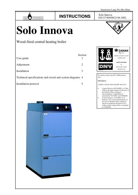
Solo Innova<br />
EN/137409/00/24-06-2002.<br />
Page 1<br />
Solo Innova<br />
Wood-fired central heating boiler<br />
Section<br />
User guide 1<br />
Adjustment 2<br />
Installation 3<br />
Technical specifications <strong>and</strong> circuit <strong>and</strong> system diagrams 4<br />
Installation protocol 5<br />
DANAK<br />
Reg. no.<br />
5001<br />
Quality assurance system<br />
certified under<br />
DS/EN ISO 9001<br />
by<br />
Det Norske Veritas<br />
Danmark A/S<br />
We hereby declare that HS TARM product<br />
type<br />
Solo Innova<br />
complies with <strong>the</strong> following EEC directives:<br />
• Council Directive 89/336/EEC of 3 May<br />
1989 on <strong>the</strong> approximation of <strong>the</strong> laws of<br />
<strong>the</strong> Member States relating to<br />
electromagnetic compatibility as<br />
amended by 92/31/EEC <strong>and</strong> 93/68/EEC<br />
• Council Directive 73/23/EEC of 19<br />
February 1973 on <strong>the</strong> harmonisation of<br />
<strong>the</strong> laws of Member States relating to<br />
electrical equipment designed <strong>for</strong> use<br />
within certain voltage limits as amended<br />
by 93/68/EEC
INSTRUCTIONS<br />
Solo Innova<br />
Page 2<br />
CONTENTS<br />
This user guide is divided into several sections. Figure numbers refer to <strong>the</strong> corresponding sections. Fig. no. 1.1.1 thus<br />
refers to Section 1.1.1. The symbol (#)-no. is used if several pictures belong to one section.<br />
Section<br />
Page<br />
1 USER GUIDE ................................................................................................................................................3<br />
1.1 DESCRIPTION OF BOILER ...........................................................................................................................3<br />
1.2 SAFETY PRECAUTIONS ..............................................................................................................................6<br />
1.3 OPERATING HINTS.....................................................................................................................................7<br />
1.4 DESCRIPTION OF THE APPARATUS ...........................................................................................................10<br />
1.5 TROUBLESHOOTING ................................................................................................................................12<br />
1.6 MAINTENANCE .......................................................................................................................................13<br />
1.7 CLEANING...............................................................................................................................................14<br />
2 AUTOMATIC OPERATION – SAVING ENERGY ...............................................................................15<br />
2.1 CONTROLLING THE BOILER WITH THE WEATHER COMPENSATION SYSTEM..............................................15<br />
3 INSTALLATION ........................................................................................................................................16<br />
3.1 STANDARDS AND REGULATIONS .............................................................................................................16<br />
3.2 SYSTEM TYPES........................................................................................................................................16<br />
3.3 INSTALLATION ........................................................................................................................................17<br />
3.4 STANDARD DELIVERY:............................................................................................................................17<br />
3.5 INSTALLATION AND PIPE CONNECTIONS..................................................................................................17<br />
3.6 EXPANSION TANK, SAFETY LINES AND PUMP SIZE ...................................................................................18<br />
3.7 ELECTRICAL CONNECTION ......................................................................................................................18<br />
3.8 COMMISSIONING THE SYSTEM.................................................................................................................19<br />
4 TECHNICAL SPECIFICATIONS AND CIRCUIT DIAGRAMS .........................................................20<br />
4.1 BOILER TECHNICAL SPECIFICATIONS.......................................................................................................20<br />
4.2 CIRCUIT DIAGRAMS ................................................................................................................................21<br />
4.3 SYSTEM LAYOUT.....................................................................................................................................23<br />
5 INSTALLATION PROTOCOL, BOILER SYSTEM ..............................................................................24<br />
5.1 MEASURED AND SET VALUES..................................................................................................................24<br />
Specifications are subject to change without notice. No responsibility can be accepted <strong>for</strong> printing errors.<br />
INSTALLATION GUIDE<br />
<strong>for</strong> HS TARM - SOLO INNOVA boiler<br />
The SOLO INNOVA is used to generate hot water. The permissible outflow temperature is 95°C <strong>and</strong><br />
<strong>the</strong> permissible total excess pressure is 2.5 bar, measured at <strong>the</strong> deepest point in <strong>the</strong> boiler system/<strong>the</strong><br />
boiler.<br />
Please note <strong>the</strong> technical specifications which are given in <strong>the</strong> table below <strong>and</strong> <strong>the</strong> type plate.<br />
The boiler should be installed as per <strong>the</strong> accompanying installation <strong>and</strong> user guide.<br />
Please observe local regulations when installing <strong>the</strong> boiler <strong>and</strong> <strong>the</strong> heating system.<br />
Regulation <strong>and</strong> limitation of <strong>the</strong> heating is by switching <strong>the</strong> fan by means of TR (temperature<br />
controller) <strong>and</strong> STB (safety temperature limiter). A max. draught of 20 Pascal may not be exceeded.<br />
All boilers are given a water pressure test of 3.25 bar in <strong>the</strong> factory.<br />
Apart from <strong>the</strong> accompanying installation instructions, a user guide with all requisite in<strong>for</strong>mation must<br />
be kept at/hung on <strong>the</strong> boiler after <strong>the</strong> boiler has been set up.<br />
Tarm, 06.03.1997<br />
HS TARM A/S<br />
Smedevej<br />
6880 Tarm<br />
Denmark
1 User guide<br />
INSTRUCTIONS<br />
Solo Innova<br />
Page 3<br />
1.1 Description of boiler<br />
7 1<br />
8<br />
9<br />
10<br />
11<br />
12<br />
13<br />
14<br />
2<br />
3<br />
4<br />
5<br />
6<br />
15<br />
Fig. 1.1<br />
1. Control panel<br />
2. Filling door<br />
3. Primary air control<br />
4. Secondary air control<br />
5. Ash door<br />
6. Sight glass<br />
7. Exhaust stack<br />
8. Cleaning damper<br />
9. Induced-draught fan<br />
10. Type plate<br />
11. Cooling spiral*<br />
12. Flue gas turbulators<br />
13. Heat exchanger pipe<br />
14. Filling chamber<br />
15. Fuel tunnel<br />
*Can be installed to left or right.
INSTRUCTIONS<br />
Solo Innova<br />
Page 4
INSTRUCTIONS<br />
Solo Innova<br />
Page 5<br />
1.1.1 Control panel (st<strong>and</strong>ard)<br />
The boiler temperature is adjusted from here.<br />
See also Section 1.4.<br />
A D C E F N H O I P<br />
Fig. 1.1.1<br />
210680.11<br />
(A)<br />
(C)<br />
(D)<br />
(E)<br />
(F)<br />
Space <strong>for</strong> wea<strong>the</strong>r compensation system<br />
Thermometer<br />
Fuse<br />
Switch <strong>for</strong> circulation pump<br />
Switch <strong>for</strong> fan<br />
(H)<br />
(I)<br />
(N)<br />
(O)<br />
(P)<br />
Overheating <strong>the</strong>rmostat – Restarting knob<br />
Thermostat<br />
Reset switch<br />
Switch to open door<br />
Minimum <strong>the</strong>rmostat<br />
1.1.2 Filling door<br />
The big filling door makes adding fuel easy.<br />
1.1.3 Primary air control<br />
The primary air of combustion is set here.<br />
1.1.4 Secondary air control<br />
The secondary air of combustion is set here.<br />
1.1.5 Ash door<br />
Combustion takes place behind this door <strong>and</strong> ashes are removed through it.<br />
1.1.6 Sight glass<br />
Combustion can be monitored through <strong>the</strong> sight glass.<br />
1.1.7 Exhaust stack<br />
An exhaust pipe is ducted to <strong>the</strong> chimney.<br />
1.1.8 Induced-draft fan<br />
Ensures <strong>the</strong> required air supply <strong>for</strong> combustion.<br />
1.1.9 Cleaning damper<br />
Detachable cleaning damper <strong>for</strong> cleaning <strong>the</strong> heat exchanger pipe.<br />
1.1.10 Type plate<br />
Indicates factory no. <strong>and</strong> type <strong>and</strong> o<strong>the</strong>r in<strong>for</strong>mation required to order spare parts.<br />
Factory no. <strong>and</strong> type can be noted in Section 5 on <strong>the</strong> last page of this user guide.<br />
1.1.11 Cooling spiral<br />
Thermal protection.<br />
1.1.12 Flue gas turbulators<br />
Ensure <strong>the</strong> correct flue gas temperature.<br />
1.1.13 Heat exchanger pipe<br />
The heat is transferred to <strong>the</strong> boiler water here.<br />
1.1.14 Filling chamber<br />
For <strong>the</strong> fire<strong>wood</strong>.<br />
1.1.15 Fuel tunnel<br />
Air of combustion is added to <strong>the</strong> flue gases <strong>and</strong> <strong>the</strong>y are burned here, ensuring high<br />
efficiency.<br />
Description of more important components (layout see Fig. l.l).
INSTRUCTIONS<br />
Solo Innova<br />
Page 6<br />
1.1.16 Function (See Fig. l.l)<br />
The Solo Innova is made <strong>for</strong> burning pieces of natural <strong>wood</strong>.<br />
An important feature is <strong>the</strong> built-in induced-draft fan (9).<br />
Both primary <strong>and</strong> secondary air are added to <strong>the</strong> combustion chamber via an air channel<br />
at exactly <strong>the</strong> speed required <strong>for</strong> uni<strong>for</strong>m combustion.<br />
The primary air (3) is ducted to <strong>the</strong> lower section of <strong>the</strong> filling chamber.<br />
The secondary air (4) is ducted fur<strong>the</strong>r through <strong>the</strong> fuel tunnel, where it is heated <strong>and</strong><br />
divided via two channels <strong>and</strong> <strong>the</strong> combustion nozzle. It is <strong>the</strong>n blown directly into <strong>the</strong><br />
flame at high speed to complete <strong>the</strong> combustion.<br />
A noteworthy construction feature is <strong>the</strong> special ceramic fuel tunnel (15) in <strong>the</strong> heart of<br />
<strong>the</strong> boiler which ensures that <strong>the</strong> combustion temperature reaches more than 1000°C.<br />
Combustion is efficient <strong>and</strong> soot-free, <strong>and</strong> ensures optimal economy.<br />
The heat is supplied to <strong>the</strong> boiler water via <strong>the</strong> heat exchanger pipe (13) at <strong>the</strong> rear of <strong>the</strong><br />
boiler.<br />
Fig. 1.1.16<br />
Mixing of <strong>the</strong> air of combustion from <strong>the</strong> fan <strong>and</strong> <strong>the</strong> gases from <strong>the</strong> <strong>wood</strong> in <strong>the</strong><br />
correct proportions is a prerequisite <strong>for</strong> optimal <strong>and</strong> environmentally friendly<br />
burning of <strong>the</strong> <strong>wood</strong> with <strong>the</strong> highest efficiency.<br />
Operation of <strong>the</strong> fan assumes that <strong>the</strong> boiler can discharge its heat continually. The<br />
Solo Innova must always be connected to a buffer tank of adequate size.<br />
1.1.17 Maintenance <strong>and</strong> guarantee<br />
The guarantee is described in more detail in <strong>the</strong> HS TARM guarantee certificate<br />
supplied with <strong>the</strong> boiler.<br />
The guarantee is valid only when <strong>the</strong> system is connected to a buffer tank.<br />
Complaints<br />
Please contact <strong>the</strong> technician/dealer who installed/supplied your boiler, who will<br />
<strong>for</strong>ward your complaint as required to <strong>the</strong> factory. Complaints may also be addressed<br />
directly to <strong>the</strong> factory.<br />
1.2 Safety precautions<br />
1.2.1 Responsibility<br />
The operator is responsible <strong>for</strong> running <strong>the</strong> boiler <strong>and</strong> complying with firing<br />
instructions. Failure to comply with <strong>the</strong> instructions can result in reduced efficiency <strong>and</strong><br />
increased environmental impact as <strong>the</strong> flue gases will not be as clean as <strong>the</strong>y should be.<br />
Faulty operation can also reduce boiler life. Correct operation (<strong>and</strong> installation) is <strong>the</strong><br />
best guarantee of long life <strong>and</strong> minimal impact on <strong>the</strong> environment. It is assumed that<br />
<strong>the</strong> operator possesses <strong>the</strong> appropriate motivation <strong>and</strong> <strong>the</strong> correct attitude <strong>for</strong> firing with<br />
<strong>wood</strong>, as a certain amount of work is still required to be able to “harvest” <strong>the</strong><br />
advantages of this environmentally friendly <strong>and</strong> economical <strong>for</strong>m of heating.<br />
1.2.2 Safety precautions<br />
If faults or defects are found, <strong>the</strong>y must be promptly rectified by a qualified heating<br />
engineer. Flue gas pipes, ventilation channels, fresh air ducts etc. may not be closed off<br />
or blocked. Inflammable liquids or materials may not be placed near <strong>the</strong> boiler.<br />
1.2.3 Maintenance<br />
The operator must maintain <strong>and</strong> clean <strong>the</strong> boiler <strong>and</strong> any extra equipment in accordance<br />
with:<br />
– general practice<br />
– <strong>the</strong> instructions in this user guide<br />
– <strong>the</strong> instructions <strong>for</strong> any optional equipment/accessories<br />
– <strong>and</strong> <strong>the</strong> terms described in <strong>the</strong> appropriate guarantee certificate<br />
– (see Section 1.7 Cleaning, 1.6 Maintenance <strong>and</strong> <strong>the</strong> boiler’s guarantee<br />
certificate).
1.3 Operating hints<br />
1.3.1 Wood as fuel<br />
INSTRUCTIONS<br />
Solo Innova<br />
Page 7<br />
The Solo Innova is made to burn natural <strong>for</strong>est <strong>wood</strong>. Both hard<strong>wood</strong> <strong>and</strong> soft<strong>wood</strong> are<br />
suitable, but oak should not be burned as <strong>the</strong> only source of <strong>wood</strong> <strong>for</strong> long periods<br />
because of its high acid content.<br />
The <strong>wood</strong> must be dry, i.e. moisture content 15-25%. The <strong>wood</strong> must be dry <strong>for</strong> good<br />
combustion <strong>and</strong> to achieve its best calorific value.<br />
The <strong>wood</strong> will dry out most quickly if it is cut into <strong>the</strong> appropriate length <strong>and</strong> split into<br />
pieces 10-12 cm thick. The best length is 1/2 metre <strong>for</strong> <strong>the</strong> Solo Innova 30-50 <strong>and</strong> 1/3<br />
metre <strong>for</strong> <strong>the</strong> Solo Innova 20.<br />
The <strong>wood</strong> is best stored in <strong>the</strong> open air under cover, but it can also be stored uncovered.<br />
The <strong>wood</strong> will dry most quickly if it is carefully stacked alternatively lengthwise <strong>and</strong><br />
crosswise so that air can penetrate into <strong>the</strong> stack.<br />
The <strong>wood</strong> should be stored <strong>for</strong> at least one <strong>and</strong> a half years.<br />
Chopped <strong>wood</strong><br />
Briquettes<br />
Coal<br />
Maximum fill height<br />
(e.g. waste <strong>wood</strong> <strong>and</strong> <strong>wood</strong> chips) are less suitable as fuel. On <strong>the</strong> one h<strong>and</strong> <strong>the</strong>y can fall<br />
down <strong>the</strong> gap between <strong>the</strong> ceramic bricks <strong>and</strong> on <strong>the</strong> o<strong>the</strong>r h<strong>and</strong> it can be difficult to<br />
control <strong>the</strong> combustion process effectively. The disadvantages can, <strong>for</strong> example, include<br />
reduced efficiency, soot etc. Impregnated or painted <strong>wood</strong> is unsuitable as fuel. The<br />
Solo Innova is designed <strong>for</strong> <strong>for</strong>est <strong>wood</strong>. Wood is an environmentally friendly fuel as it<br />
is CO 2 -neutral.<br />
Wood briquettes or straw can also be used as fuel, e.g. with a diameter of 60 mm <strong>and</strong> a<br />
length of 50-100 mm.<br />
Excessively small <strong>and</strong> compact pieces of <strong>wood</strong> or straw <strong>pellet</strong>s are not suitable.<br />
Coal cannot be used as it becomes too compact <strong>and</strong> closes <strong>the</strong> fuel slit.<br />
The filling chamber can be filled to <strong>the</strong> top.<br />
1.3.2 Be<strong>for</strong>e using<br />
1. Check <strong>the</strong> water pressure be<strong>for</strong>e using <strong>the</strong> system.<br />
2. The pump <strong>and</strong> <strong>the</strong> fan must be switched off when filling with water. This is most<br />
easily done at <strong>the</strong> main switch on <strong>the</strong> wall. (See Section 1.6 - Maintenance).<br />
N.B.: Water may not be added to <strong>the</strong> boiler while it is running.<br />
3. When filling, <strong>the</strong> system must be bled via <strong>the</strong> venting screw.<br />
1.3.3 Commissioning <strong>the</strong> boiler<br />
A D C E F N H O I P<br />
210680.11<br />
1. Switch on <strong>the</strong> main switch on <strong>the</strong> wall.<br />
2. Fill with fuel (see Section 1.3.8 or 1.3.9).<br />
3. Switch on <strong>the</strong> switches <strong>for</strong> <strong>the</strong> pump (E) <strong>and</strong> <strong>the</strong> fan (F). Set <strong>the</strong> <strong>the</strong>rmostat (I) to<br />
<strong>the</strong> desired temperature. Press <strong>the</strong> reset button (N).<br />
4. Light <strong>the</strong> fire as in Section 1.3.7.<br />
5. The boiler will start if heating is required.<br />
6. See Section 1.5 – Troubleshooting if <strong>the</strong>re are problems starting.<br />
1.3.4 Shutting down <strong>the</strong> boiler<br />
1. Switch off <strong>the</strong> boiler at <strong>the</strong> main switch on <strong>the</strong> wall.<br />
2. Then switch off <strong>the</strong> boiler/<strong>the</strong> circulation pump at switches (E) <strong>and</strong> (F).
INSTRUCTIONS<br />
Solo Innova<br />
Page 8<br />
1.3.5 Connecting a buffer tank<br />
The correct proportions of air of combustion from <strong>the</strong> fan <strong>and</strong> gases from <strong>the</strong> <strong>wood</strong> are a<br />
prerequisite <strong>for</strong> optimal <strong>and</strong> environmentally friendly burning of <strong>the</strong> <strong>wood</strong> with <strong>the</strong><br />
highest possible efficiency. Operation of <strong>the</strong> fan assumes that <strong>the</strong> boiler can continually<br />
discharge its heat. HS TARM <strong>the</strong>re<strong>for</strong>e recommends that a buffer tank always be<br />
connected.<br />
1.3.6 Tar in <strong>the</strong> combustion chamber<br />
Tar deposits are not normally a problem in a Solo Innova which is fired as directed (see<br />
section 1.3.12 – Operation with buffer tank).<br />
1.3.7 Preheating<br />
1.3.8 Putting in <strong>wood</strong><br />
1) Switch on <strong>the</strong> fan with <strong>the</strong> switch on <strong>the</strong> control panel (F) (Setting I).<br />
2) Press door open switch O <strong>and</strong> open <strong>the</strong> door.<br />
3) Insert pieces of <strong>wood</strong> <strong>and</strong> paper.<br />
4) Light <strong>the</strong> <strong>wood</strong> <strong>and</strong> <strong>the</strong> paper. Close <strong>the</strong> door.<br />
5) Switch on <strong>the</strong> fan switch (F).<br />
6) Press <strong>the</strong> reset switch (N). The fan will start.<br />
7) Add fuel when <strong>the</strong> embers are about 150 mm high.<br />
– Combustion will be in progress after about 5-10 minutes.<br />
It is very important not to add so much <strong>wood</strong> than that <strong>the</strong> heat of combustion cannot be<br />
stored in <strong>the</strong> reservoir. The maximum temperature should only be reached when <strong>the</strong><br />
<strong>wood</strong> has burned. THE FAN SHOULD NOT SWITCH OFF BEFORE THE WOOD<br />
HAS BURNED*) IF THE FAN SWITCHES OFF BEFORE THIS, THERE IS TOO<br />
MUCH WOOD. MAKE THE BEST POSSIBLE USE OF THE RESERVOIR AND DO<br />
NOT ADD TOO MUCH WOOD. See also 1.3.12<br />
*) Waiting time <strong>and</strong> starting/stopping of <strong>the</strong> fan do not give clean combustion. It is also<br />
bad <strong>for</strong> <strong>the</strong> boiler as condensation will occur in <strong>the</strong> filling chamber, causing corrosion in<br />
<strong>the</strong> steel walls.<br />
1.3.9 Adding <strong>wood</strong><br />
1) Switch on <strong>the</strong> fan with <strong>the</strong> switch on <strong>the</strong> control panel (F) (Setting I).<br />
2) Press <strong>the</strong> door open switch.<br />
3) Open <strong>the</strong> filling door 2 cm with <strong>the</strong> left h<strong>and</strong>.<br />
4) Wait about 20 seconds.<br />
5) Slowly open <strong>the</strong> door.<br />
6) Add <strong>wood</strong>. Try to stack <strong>the</strong> <strong>wood</strong> as evenly as possible.<br />
7) Close <strong>the</strong> door.<br />
8) Switch on <strong>the</strong> fan switch (F).<br />
9) Press <strong>the</strong> reset switch (N).<br />
1.3.10 Daily firing <strong>and</strong> warming up<br />
The warming up procedure <strong>for</strong> daily use is <strong>the</strong> same as was done <strong>the</strong> first time. Use<br />
pieces of <strong>wood</strong> <strong>and</strong> paper. Stir up <strong>the</strong> ashes when <strong>the</strong> fire is underway. Add more <strong>wood</strong>,<br />
close <strong>the</strong> door <strong>and</strong> switch on <strong>the</strong> fan. The newly added <strong>wood</strong> will now ignite.<br />
Operation<br />
The fuel tunnel (behind <strong>the</strong> ash door) must be kept reasonably free of ashes <strong>and</strong> small<br />
half-burned pieces of <strong>wood</strong>. Use <strong>the</strong> scraper to keep <strong>the</strong> tunnel clean <strong>and</strong> leave <strong>the</strong> small<br />
pieces of <strong>wood</strong> in front of <strong>the</strong> tunnel, where <strong>the</strong>y will burn. It is useful to check <strong>the</strong><br />
tunnel each time it is warmed up <strong>and</strong> to clean carefully as required.<br />
Storing <strong>the</strong> fuel. Wood may not be stored in <strong>the</strong> boiler room. The <strong>wood</strong> is best<br />
protected from rain, stored under cover.<br />
1.3.11 Transport protectors<br />
The transport protectors <strong>for</strong> <strong>the</strong> ceramic bricks are made of <strong>wood</strong> <strong>and</strong> will quickly burn.<br />
Do not try to remove <strong>the</strong>m.
3<br />
4<br />
6<br />
INSTRUCTIONS<br />
Solo Innova<br />
Page 9<br />
1.3.12 Operation with buffer tank<br />
HS TARM recommends permanent connection of a HS TARM buffer tank (see Section<br />
4.3):<br />
– The boiler will always be able to discharge its heat.<br />
– Better combustion, less depositing of soot <strong>and</strong> tar, longer boiler life.<br />
– Simpler operation as <strong>the</strong> filling chamber can be completely filled.<br />
– The boiler can be fired when you have time <strong>and</strong> <strong>the</strong> house can be supplied with<br />
heating as required from <strong>the</strong> buffer tank.<br />
– Hot tap water from a container in <strong>the</strong> buffer tank (HS TARM will be happy to<br />
assist with calculating <strong>the</strong> buffer tank size).<br />
– The amount of <strong>wood</strong> placed in <strong>the</strong> boiler’s filling chamber depends on <strong>the</strong> size<br />
<strong>and</strong> <strong>the</strong> temperature of <strong>the</strong> buffer tank. The boiler should not be fired beyond <strong>the</strong><br />
reservoir’s heat storage capacity.<br />
– Do not add <strong>wood</strong> until <strong>the</strong> temperature in <strong>the</strong> buffer tank has fallen to 40-50°C so<br />
that <strong>the</strong> reservoir will again be able to absorb heat.<br />
– Set <strong>the</strong> boiler temperature to 90°C, i.e. almost maximum.<br />
– Clean <strong>the</strong> boiler regularly (see Section 1.7).<br />
Fig. 1.3.13#1<br />
1.3.13 Adjusting combustion<br />
Manual air setting – st<strong>and</strong>ard values<br />
Boiler type Primary air<br />
(damper 3)<br />
Secondary air<br />
(damper 4)<br />
Hard<strong>wood</strong> (beech <strong>and</strong> birch)<br />
-Solo Innova 20 50% 50%<br />
-Solo Innova 30 50% 50%<br />
-Solo Innova 50 75-100% 75-100%<br />
Soft<strong>wood</strong> (conifers)<br />
-Solo Innova 20 100% 0-10%<br />
-Solo Innova 30 100% 0-10%<br />
-Solo Innova 50 100% 20%<br />
The Solo Innova features primary <strong>and</strong> secondary air combustion<br />
<strong>for</strong> optimal burning.<br />
Combustion is controlled with primary air adjustment 3 <strong>and</strong><br />
secondary air adjustment 4. Both are normally 75% open*).<br />
Combustion is stable after about 45 minutes of operation <strong>and</strong> <strong>the</strong><br />
secondary air may be turned off.<br />
Observe <strong>the</strong> combustion through <strong>the</strong> sight glass 6.<br />
The flame should be yellow <strong>and</strong> pale bluish, <strong>and</strong> <strong>the</strong> flame length<br />
should be appropriate (see below).<br />
It is normally only necessary to adjust <strong>the</strong> setting if <strong>the</strong> fuel is<br />
changed.<br />
*)If full output is required, <strong>the</strong>y can be opened 100%.<br />
Fig. 1.3.13#2<br />
Too much air.<br />
Flame too short <strong>and</strong> bluish.<br />
Reduce secondary air.<br />
Fig. 1.3.13#3<br />
Too little air.<br />
Flame too long <strong>and</strong> reddish yellow.<br />
Increase secondary air.<br />
Fig. 1.3.13#4<br />
Correct setting.<br />
The flame is yellow <strong>and</strong> pale bluish.
1.4 Description of <strong>the</strong> apparatus<br />
INSTRUCTIONS<br />
Solo Innova<br />
Page 10<br />
1.4.1 Control panel – <strong>the</strong> boiler temperature is set from here.<br />
A D C E F N H O I P<br />
(A)<br />
(C)<br />
(D)<br />
(E)<br />
(F)<br />
Fig. 1.4.1<br />
Space <strong>for</strong> wea<strong>the</strong>r compensation system<br />
Thermometer<br />
Fuse<br />
Switch <strong>for</strong> circulation pump<br />
Fan switch<br />
(H)<br />
(I)<br />
(N)<br />
(O)<br />
(P)<br />
210680.11<br />
Overheating <strong>the</strong>rmostat – restarting button<br />
Thermostat<br />
Reset switch<br />
Door open switch<br />
Minimum <strong>the</strong>rmostat<br />
(A)<br />
Space <strong>for</strong> wea<strong>the</strong>r compensation system.<br />
(C)<br />
(D)<br />
(E)<br />
(F)<br />
(H)<br />
(I)<br />
Thermometer. Shows <strong>the</strong> boiler temperature. The boiler temperature is adjusted via <strong>the</strong>rmostat (I).<br />
Fuse max. 6.3 A (5 x 20 mm).<br />
Switch <strong>for</strong> circulation pump.<br />
Fan switch (should always be set at I).<br />
Overheating <strong>the</strong>rmostat – switches off <strong>the</strong> fan when <strong>the</strong> boiler temperature is approx. 100°C. Wait until <strong>the</strong><br />
boiler temperature has fallen to 75°C. To switch on again, unscrew <strong>the</strong> protective cap <strong>and</strong> push in <strong>the</strong> ejected<br />
pin.<br />
Thermostat 85-93°C. Recommended set temperature 85-90°C.<br />
To ensure that <strong>the</strong> temperature is not set at less that 80°C, a stop screw is mounted under <strong>the</strong> knob.<br />
(N) Reset switch. The fan switches off automatically if <strong>the</strong> boiler has burned out <strong>and</strong> <strong>the</strong> boiler/flue gas<br />
temperature falls.<br />
– In units with buffer tank, <strong>the</strong> fan switches off when <strong>the</strong> temperature at <strong>the</strong> sensor in <strong>the</strong> flue gas has reached<br />
90°C.<br />
– If <strong>the</strong> temperature at <strong>the</strong> sensor falls below 90°C, <strong>the</strong> reset switch (N) must be pressed to restart combustion<br />
in <strong>the</strong> boiler.<br />
(O)<br />
(P)<br />
Door open switch – ensures that children cannot open <strong>the</strong> door.<br />
The minimum <strong>the</strong>rmostat switches off <strong>the</strong> fan <strong>and</strong> <strong>the</strong> pump when <strong>the</strong> <strong>wood</strong> has burned out.
1.4.2 Fan<br />
INSTRUCTIONS<br />
The total air flow is set at <strong>the</strong> factory.<br />
Solo Innova<br />
Page 11<br />
1.4.3 Thermal outflow protection<br />
The st<strong>and</strong>ard version of <strong>the</strong> Solo Innova does not have a cooling spiral. This spiral can<br />
be mounted to <strong>the</strong> left or <strong>the</strong> right.<br />
1.4.4 Flue gas turbulators<br />
The flue gas turbulators are in <strong>the</strong> heat exchanger pipe <strong>and</strong> reduce <strong>the</strong> flue gas<br />
temperature.<br />
1.4.5 Load valve<br />
The <strong>the</strong>rmostatic load valve enables <strong>the</strong> boiler to remain at a high temperature. As <strong>the</strong><br />
valve only opens at 65°C, <strong>the</strong> boiler <strong>the</strong>rmostat must be set higher (i.e. fixed max. 90-<br />
95°C). The load valve is supplied as a separate valve or as a complete pipe complex<br />
ready <strong>for</strong> installation in <strong>the</strong> boiler. (See functional description of <strong>the</strong> load valve in<br />
Section 4.3).<br />
The guarantee is not valid unless a <strong>the</strong>rmostatic load valve is installed.<br />
1.4.6 Draught limiter<br />
If <strong>the</strong> chimney draught is excessive, a draught limiter can be built into <strong>the</strong> chimney (see<br />
Section 3.3.3).
1.5 Troubleshooting<br />
1.5.1 Troubleshooting<br />
INSTRUCTIONS<br />
Solo Innova<br />
Page 12<br />
Problem Problem<br />
Possible cause/==> possible solution<br />
No.<br />
1. No heat in <strong>the</strong> system A: Thermostat (I) set too low.<br />
Set <strong>the</strong>rmostat higher.<br />
B: Fan cut out because <strong>the</strong> min. <strong>the</strong>rmostat temperature<br />
has fallen below 90°C.<br />
Press reset switch (N).<br />
C: Overheating <strong>the</strong>rmostat triggered.<br />
Press knob in again.<br />
D: Mixer (if present) fully or partly closed.<br />
Open.<br />
E: Circulation pump not running.<br />
Switch on.<br />
F: Insufficient water in <strong>the</strong> system; air in <strong>the</strong> system.<br />
Top up <strong>and</strong> bleed.<br />
N.B.: Never add water to an overheated boiler.<br />
Wait until <strong>the</strong> boiler has cooled down.<br />
G: Regulator may have switched off <strong>the</strong> system.<br />
See user guide <strong>for</strong> regulator.<br />
H: Fuse (D) blown.<br />
Replace fuse in boiler control<br />
(see Fig. 1.4.1).<br />
Call a serviceman if you cannot determine <strong>the</strong> cause.<br />
2. Combustion will not stop.<br />
If combustion continues despite switching off <strong>the</strong> fan at <strong>the</strong><br />
<strong>the</strong>rmostat (I) or <strong>the</strong> switch (F), <strong>the</strong> problem may be an excessive<br />
chimney draught.<br />
If this is <strong>the</strong> cause, a draught limiter should be built into <strong>the</strong><br />
chimney. Consult your serviceman <strong>and</strong> chimney sweep about<br />
purchase <strong>and</strong> installation (see Section 3.3.3).<br />
3. Loss of pressure in <strong>the</strong> system. Bleed <strong>the</strong> system <strong>and</strong> add water.<br />
(See Section 1.6 Maintenance)<br />
Call a serviceman if <strong>the</strong> pressure continues to fall.<br />
4. The fan does not switch off although <strong>the</strong><br />
min. <strong>the</strong>rmostat temperature has fallen below 90°C.<br />
If <strong>the</strong> boiler is operated from cold, <strong>the</strong> boiler temperature must<br />
reach normal operating temperature (above 80°C) to switch over<br />
<strong>the</strong> min. <strong>the</strong>rmostat. If normal operating temperature is not<br />
reached, <strong>the</strong> fan will not switch off but continue to run, even<br />
though <strong>the</strong> <strong>wood</strong> has burned out <strong>and</strong> <strong>the</strong> min. <strong>the</strong>rmostat<br />
temperature has fallen below 90°C.<br />
Ensure that <strong>the</strong> boiler is brought to normal operating<br />
temperature (about 85-90°C) each time it is used.<br />
1.5.2 Maintenance tips<br />
What causes poor boiler per<strong>for</strong>mance <strong>and</strong> why doesn’t <strong>the</strong> flame length in <strong>the</strong> fuel<br />
tunnel change when <strong>the</strong> adjustment <strong>for</strong> secondary air is changed?<br />
It is important to use <strong>wood</strong> of an appropriate size (length <strong>and</strong> diameter) <strong>and</strong> to stack it<br />
properly so that <strong>the</strong>re are no “holes” <strong>and</strong> “hanging pieces” in <strong>the</strong> <strong>wood</strong> stack, which<br />
must <strong>the</strong>n be regularly stirred with <strong>the</strong> poker to <strong>for</strong>m it into a compact mass.<br />
The diameter of <strong>the</strong> <strong>wood</strong> may not exceed 10-12 cm as “holes” would <strong>the</strong>n <strong>for</strong>m more<br />
easily in <strong>the</strong> <strong>wood</strong> layer, creating a risk of reduced heating output. Thick pieces of <strong>wood</strong><br />
must be split to a diameter of 10-12 cm.<br />
See Section 1.3.13 <strong>for</strong> correct flame length.
INSTRUCTIONS<br />
Solo Innova<br />
Page 13<br />
1.6 Maintenance<br />
1.6.1 Adding water<br />
The pump <strong>and</strong> <strong>the</strong> fan must be switched off when adding water to <strong>the</strong> system. It is<br />
easiest to switch off <strong>the</strong> main switch on <strong>the</strong> wall, so that all pumps <strong>and</strong> <strong>the</strong> fan etc. are<br />
switched off.<br />
N.B.: Do not add water to an overheated boiler in operation.<br />
Water may be added via <strong>the</strong> KFE cock (Fig. 1.6.1) with <strong>the</strong> aid of a hose connected to<br />
<strong>the</strong> tap. The hose must be filled with water be<strong>for</strong>e connection so that no air can enter <strong>the</strong><br />
system.<br />
First open <strong>the</strong> KFE cock. Then slowly turn on <strong>the</strong> water tap <strong>and</strong> fill <strong>the</strong> system until <strong>the</strong><br />
water runs out of <strong>the</strong> expansion tank overflow. Then turn off <strong>the</strong> tap followed by <strong>the</strong><br />
KFE cock. The system must be bled via <strong>the</strong> venting screw during filling.<br />
Fig. 1.6.1<br />
1.6.2 Protection against freezing<br />
The central heating system can be protected against freezing with anti-freeze, but please<br />
note that this does not protect <strong>the</strong> cooling spiral. If you desire protection against<br />
freezing, we recommend calling a serviceman to add <strong>the</strong> anti-freeze.<br />
1.6.3 Replacing <strong>the</strong> door seals<br />
1. Remove <strong>the</strong> two pins <strong>and</strong> take off <strong>the</strong> door.<br />
2. Remove <strong>the</strong> old sealing with a screwdriver or a chisel.<br />
3. Clean <strong>the</strong> sealing groove.<br />
4. Press new sealing into <strong>the</strong> groove. When half <strong>the</strong> sealing has been inserted,<br />
adjust <strong>the</strong> end <strong>and</strong> press in <strong>the</strong> rest.<br />
5. Secure <strong>the</strong> sealing by gently tapping with a hammer.<br />
6. Replace <strong>the</strong> door.<br />
1.6.4 Replacing <strong>the</strong> fuel tunnel<br />
If <strong>the</strong> fuel tunnel has to be replaced, directions are supplied with <strong>the</strong> packet of<br />
replacement bricks.<br />
1.6.5 Good advice<br />
Keep <strong>the</strong> temperature at about 20°C in occupied rooms <strong>and</strong> lower in unused rooms.<br />
Give <strong>the</strong> house a quick but effective airing every day. Turn off <strong>the</strong> boiler while doing<br />
so.<br />
DO NOT FORGET to check any safety valves <strong>and</strong> anode in any connected hot water<br />
reservoir.
1.7 Cleaning<br />
INSTRUCTIONS<br />
Solo Innova<br />
Page 14<br />
The boiler must be cleaned regularly. Lack of cleaning can result in malfunctioning <strong>and</strong><br />
reduced life.<br />
1.7.1 Flue gas collection box <strong>and</strong> heat exchanger pipes<br />
Clean <strong>the</strong> flue gas collection box <strong>and</strong> <strong>the</strong> heat exchanger pipes twice a month with <strong>the</strong><br />
brush. Insert <strong>the</strong> brush into each heat exchanger pipe <strong>and</strong> work back <strong>and</strong> <strong>for</strong>th<br />
thoroughly.<br />
Push <strong>the</strong> brush all <strong>the</strong> way through, but be careful not to damage <strong>the</strong> bottom plate<br />
underneath. A rotating cleaning brush <strong>for</strong> a drill (min. 400 watt) is available as an<br />
optional extra. This enables easier <strong>and</strong> more effective cleaning. Clean heat exchanger<br />
pipes <strong>and</strong> a clean flue gas collection box mean better operating economy.<br />
1.7.2 Combustion chamber/filling chamber<br />
A B C D<br />
Clean <strong>the</strong> combustion chamber/filling chamber once or twice a month. From <strong>the</strong> top<br />
filling door, scrape <strong>the</strong> ash through <strong>the</strong> fire gap with <strong>the</strong> scraper. The ash is <strong>the</strong>n scraped<br />
out <strong>for</strong>wards from <strong>the</strong> ash door on to <strong>the</strong> boiler floor, <strong>and</strong> <strong>the</strong>n out into <strong>the</strong> ash box.<br />
Extra walls<br />
Extra walls are fitted in <strong>the</strong> filling chamber (C - Fig. 1.7.2). These should be taken off<br />
once a month <strong>and</strong> any deposits behind <strong>the</strong>m cleaned.<br />
The ventilation holes in each side should be kept open.<br />
Fig. 1.7.2<br />
S000055X<br />
1.7.3 Fan <strong>and</strong> air damper<br />
The impeller (A - Fig. 1.7.2) must be inspected regularly <strong>and</strong> cleaned as necessary with<br />
a stiff brush (about four times a year).<br />
Please check carefully – even a thin coating significantly reduces <strong>the</strong> air flow <strong>and</strong><br />
must be removed.<br />
When <strong>the</strong> exhaust stack is connected vertically directly under <strong>the</strong> chimney, <strong>the</strong> fan must<br />
always be removed <strong>and</strong> cleaned after each cleaning of <strong>the</strong> chimney.<br />
N.B. If <strong>the</strong> fan motor is blocked because of lack of cleaning, <strong>the</strong> motor can be ruined.<br />
1.7.4 Cleaning <strong>the</strong> air channels<br />
The primary air channels (on both sides of <strong>the</strong> boiler) can occasionally become blocked.<br />
Be<strong>for</strong>e <strong>the</strong> air channels can be cleaned, <strong>the</strong> diffuser (A - Fig. 1.7.2) must first be<br />
removed (4 nuts). The air channels can be cleaned with <strong>the</strong> brush provided. The diffuser<br />
should be reinstalled with care. Remember <strong>the</strong> seal.<br />
1.7.5 Removing <strong>the</strong> ash<br />
The ash from <strong>the</strong> heat exchanger pipes <strong>and</strong> <strong>the</strong> combustion chamber is scraped out<br />
through <strong>the</strong> ash door <strong>and</strong> into <strong>the</strong> ash box with <strong>the</strong> aid of <strong>the</strong> scraper provided (or a<br />
vacuum cleaner may be used).<br />
1.7.6 Cleaning <strong>the</strong> casing<br />
Soot on <strong>the</strong> casing <strong>and</strong> <strong>the</strong> doors can be removed with a cleaner containing ammonium<br />
chloride <strong>and</strong> acetic acid. Clean <strong>the</strong> casing regularly as required to preserve <strong>the</strong> boiler’s<br />
appearance.
INSTRUCTIONS<br />
Solo Innova<br />
Page 15<br />
2 Automatic operation – saving energy<br />
The boiler is highly efficient <strong>and</strong> well insulated. Significant savings can never<strong>the</strong>less be<br />
made by automating <strong>the</strong> boiler’s operation, i.e. no heating in <strong>the</strong> house during periods<br />
when it is not necessary.<br />
2.1 Controlling <strong>the</strong> boiler with <strong>the</strong> wea<strong>the</strong>r compensation system<br />
HS TARM offers several br<strong>and</strong>s of wea<strong>the</strong>r compensation system.<br />
The equipment consists of:<br />
Control unit (<strong>for</strong> installation in <strong>the</strong> control panel).<br />
Mixer motor (<strong>for</strong> connecting to <strong>the</strong> mixer. The motor can be installed on a mixer which<br />
is already built in without emptying <strong>the</strong> system.)<br />
Outside temperature sensor (<strong>for</strong> mounting on a north wall).<br />
Outflow temperature sensor (<strong>for</strong> installation in <strong>the</strong> outflow line after <strong>the</strong> mixer).<br />
The outflow temperature is automatically adapted to <strong>the</strong> outside temperature.<br />
The control unit has a built-in seven-day clock, permitting a lowering of <strong>the</strong> temperature<br />
to be set separately <strong>for</strong> each day. As <strong>the</strong> Solo Innova must always be able to discharge<br />
its heat, <strong>the</strong> wea<strong>the</strong>r compensation system is recommended only <strong>for</strong> <strong>the</strong> buffer tank<br />
mixer.
3 Installation<br />
3.1 St<strong>and</strong>ards <strong>and</strong> regulations<br />
INSTRUCTIONS<br />
Solo Innova<br />
Page 16<br />
3.1.1 Boiler room<br />
The boiler should be set up in a separate boiler room.<br />
Ensure that <strong>the</strong>re is a proper supply of fresh air <strong>for</strong> correct combustion.<br />
Set up <strong>the</strong> boiler in <strong>the</strong> boiler room.<br />
Because of <strong>the</strong> noise made by <strong>the</strong> fan motor <strong>and</strong> <strong>the</strong> combustion (about <strong>the</strong> same level<br />
as in a modern oil-fired boiler), installing <strong>the</strong> Solo Innova close to a room where noise<br />
may be a problem is not recommended.<br />
Please observe <strong>the</strong> guidelines <strong>and</strong> <strong>the</strong> various national <strong>and</strong> local regulations.<br />
Solo Innova boilers are designed <strong>and</strong> approved as heaters <strong>for</strong> hot water systems with<br />
permissible outflow temperatures of up to 95°C.<br />
3.1.2 Firing with <strong>wood</strong><br />
A large number of different gases is generated when <strong>wood</strong> burns. These gases constitute<br />
<strong>the</strong> main part of <strong>the</strong> <strong>wood</strong>’s calorific value <strong>and</strong> contain <strong>for</strong>mic <strong>and</strong> acetic acids. When<br />
<strong>the</strong> boiler fan is running, <strong>the</strong> gases are mixed in <strong>the</strong> correct proportions with air of<br />
combustion at high temperature. Combustion is <strong>the</strong>n very efficient <strong>and</strong> soot-free, <strong>the</strong>re<br />
is optimal economy of combustion (high efficiency), <strong>and</strong> boiler life is preserved. At <strong>the</strong><br />
same time, <strong>the</strong> environment is best protected, as <strong>the</strong> tar <strong>and</strong> dust etc. content in <strong>the</strong> flue<br />
gas is low.<br />
Optimal <strong>and</strong> environmentally friendly burning of <strong>the</strong> <strong>wood</strong> requires mixing of <strong>the</strong> air of<br />
combustion from <strong>the</strong> fan <strong>and</strong> gases from <strong>the</strong> fuel in <strong>the</strong> correct proportions. Fan<br />
operation assumes that <strong>the</strong> boiler can always discharge its heat, <strong>and</strong> HS TARM<br />
<strong>the</strong>re<strong>for</strong>e always recommends that <strong>the</strong> Solo Innova be connected to a HS TARM<br />
buffer tank.<br />
3.2 System types<br />
3.2.1 Operation with buffer tank<br />
HS TARM recommends permanent connection of a HS TARM buffer tank to <strong>the</strong> Solo<br />
Innova. See system diagram Section 4.3.<br />
3.2.2 Buffer tank size<br />
3.2.3 Load valve<br />
This offers <strong>the</strong> following advantages:<br />
The boiler can always discharge its heat.<br />
Improved combustion, greater efficiency, lower fuel consumption.<br />
<br />
<br />
<br />
Better environmental protection, less soot <strong>and</strong> tar build-up.<br />
Longer boiler life.<br />
Greater operating com<strong>for</strong>t. Firing occurs when required. The filling chamber can be<br />
filled completely. The buffer tank provides <strong>the</strong> house with heating/hot water as<br />
required.<br />
HS TARM supplies complete buffer tanks in sizes 500 <strong>and</strong> 750 litres, with <strong>and</strong> without<br />
built-in hot water reservoir. Types 500 B <strong>and</strong> 750 B with hot water reservoirs are<br />
equipped with two connections <strong>for</strong> installing electric heating elements. The buffer tanks<br />
are heavily insulated with CFC-free polyurethane foam.<br />
If buffer tank size is to be determined by ease of use <strong>and</strong> boiler operating conditions, a<br />
minimum reservoir volume as specified in <strong>the</strong> table in Section 4 (Technical<br />
specifications) is recommended.<br />
HS TARM will be happy to assist in calculating <strong>the</strong> reservoir size if a bigger buffer tank<br />
is desired in order to cover heating <strong>and</strong> hot water requirements over a longer period.<br />
The guarantee is not valid unless a <strong>the</strong>rmostatic load valve is installed (see Section 1.4.5<br />
<strong>and</strong> <strong>the</strong> tables in Section 4.3).
3.3 Installation<br />
INSTRUCTIONS<br />
Solo Innova<br />
Page 17<br />
Boiler size should correspond with <strong>the</strong> house’s heating requirements <strong>and</strong> not be made to<br />
depend on <strong>the</strong> size of <strong>the</strong> filling chamber.<br />
3.3.1 Who may install <strong>the</strong> boiler?<br />
The heating engineer must possess <strong>the</strong> necessary training <strong>and</strong> authorisation to install <strong>the</strong><br />
boiler.<br />
3.3.2 Chimney <strong>and</strong> chimney draught<br />
The flue gas temperature in a clean boiler is about 150°C.<br />
The chimney should be able to accommodate this temperature.<br />
As <strong>the</strong> Solo Innova has a built-in fan, only minor dem<strong>and</strong>s are made on <strong>the</strong> chimney<br />
draught. The correct chimney draught is 10-15 Pascal. The chimney can <strong>the</strong>re<strong>for</strong>e be<br />
lower than <strong>for</strong> <strong>the</strong> usual solid fuel boilers. Relevant st<strong>and</strong>ards <strong>and</strong> regulations must be<br />
observed <strong>for</strong> <strong>the</strong> chimney shape. An excessive diameter or inadequate insulation can<br />
result in sooting. Please consult a chimney sweep.<br />
We recommend connecting <strong>the</strong> boiler’s exhaust stack back to <strong>the</strong> chimney at an angle or<br />
horizontally.<br />
The exhaust stack can also be connected vertically, but <strong>the</strong> fan impeller must <strong>the</strong>n be<br />
removed each time <strong>the</strong> chimney is cleaned <strong>and</strong> ash/soot removed.<br />
3.3.3 Excessive chimney draught draught limiter<br />
Strong directional wind or a very high chimney can cause such a high chimney draught<br />
in some circumstances that combustion continues even though <strong>the</strong> fan has been switched<br />
off. The solution here is building in a draught limiter so that <strong>the</strong> chimney draught can be<br />
set to 10-15 Pascal. The chimney sweep should be consulted first. A draught limiter is<br />
available from HS TARM as an accessory <strong>for</strong> <strong>the</strong> boiler (A solid draught limiter in<br />
stainless steel with outer bearing <strong>and</strong> good control accuracy). The draught limiter can be<br />
built in, in positions 1-2 or 3.<br />
Fig. 3.3.3<br />
3.4 St<strong>and</strong>ard delivery:<br />
<br />
<br />
<br />
<br />
<br />
Boiler without casing<br />
Casing<br />
Cleaning tool<br />
Ash box<br />
Boiler regulator<br />
3.5 Installation <strong>and</strong> pipe connections<br />
3.5.1 Installation<br />
<br />
<br />
Set up <strong>the</strong> boiler on a stable base.<br />
Adapt <strong>the</strong> connector to <strong>the</strong> chimney.<br />
3.5.2 Casing installation<br />
1. The suction draught fan must be installed (with four wing nuts <strong>and</strong> washers) be<strong>for</strong>e<br />
<strong>the</strong> casing is attached.<br />
2. The casing should be attached as indicated in <strong>the</strong> accompanying photographic<br />
instruction.<br />
3. Place <strong>the</strong> sensors into <strong>the</strong> immersion tube. The capillary pipe must be bent<br />
carefully <strong>and</strong> “softly”. The long thin sensor should be placed in collar no. 12 <strong>for</strong><br />
<strong>the</strong> suction draught fan – see Section 4.1, Technical specifications. Place <strong>the</strong> o<strong>the</strong>r<br />
sensors in <strong>the</strong> immersion tube (21) – see Section 4.1.<br />
4. Connect pipes.<br />
5. Connect power.<br />
6. Install <strong>the</strong> casing cover <strong>and</strong> tighten with <strong>the</strong> four screws.
INSTRUCTIONS<br />
Solo Innova<br />
Page 18<br />
3.5.3 Pipe connections – choice of material<br />
A copper/steel mixture can be used <strong>for</strong> <strong>the</strong> heating side.<br />
The built-in heat exchanger is made of copper.<br />
Copper followed by galvanised piping (in <strong>the</strong> direction of <strong>the</strong> water flow) should be<br />
avoided <strong>for</strong> hot water <strong>for</strong> reasons of corrosion protection. However, galvanised cold<br />
water piping <strong>and</strong> copper piping can be used <strong>for</strong> hot water.<br />
The out- <strong>and</strong> return flows must be carefully insulated to avoid heat loss.<br />
3.5.4 Immersion tubes <strong>and</strong> collars<br />
Remember to install <strong>the</strong> immersion tube provided in <strong>the</strong> corresponding collar.<br />
(Immersion tubes are supplied with <strong>the</strong> boiler regulator.)<br />
Remember to cap collars which are not used in <strong>the</strong> chosen <strong>for</strong>m of installation.<br />
3.5.5 Protection against freezing<br />
The central heating system can be protected against freezing with anti-freeze (see 1.6.2).<br />
3.6 Expansion tank, safety lines <strong>and</strong> pump size<br />
3.6.1 Expansion tank<br />
The size of <strong>the</strong> expansion tank is determined by <strong>the</strong> total water content of <strong>the</strong> heating<br />
system.<br />
3.6.2 Safety valves <strong>and</strong> safety leads<br />
Provide safety valves, overflow from safety valve, running-dry protection <strong>and</strong><br />
expansion tank in accordance with applicable st<strong>and</strong>ards <strong>and</strong> regulations.<br />
Safety valves <strong>and</strong> running-dry protection should be installed directly at <strong>the</strong> flow pipe<br />
(no valves).<br />
3.6.3 Pump size<br />
The size of <strong>the</strong> circulation pump is determined by <strong>the</strong> size of <strong>the</strong> system <strong>and</strong> <strong>the</strong> pipe<br />
dimensions <strong>and</strong> version.<br />
3.7 Electrical connection<br />
3.7.1 Electrical connection<br />
The boiler is connected via <strong>the</strong> cable supplied: phase/neutral <strong>and</strong> earth.<br />
There must be a cut-out in <strong>the</strong> permanent installation.<br />
See Section 4 <strong>for</strong> circuit diagrams.<br />
3.7.2 Description of functions<br />
(See circuit diagram Section 4. Note in brackets (see Section 1.4).<br />
To start <strong>the</strong> boiler from cold, <strong>the</strong> reset switch (N) S7 must be pressed, after which:<br />
- Relay K2 cuts in<br />
- <strong>and</strong> remains active <strong>for</strong> <strong>the</strong> time being.<br />
- K2 switches fan M6 <strong>and</strong> circulation pump M7 on.<br />
When <strong>the</strong> boiler temperature reaches <strong>the</strong> min. <strong>the</strong>rmostat setting - B15<br />
- K2 cuts out.<br />
Boiler <strong>the</strong>rmostat B16 <strong>the</strong>n regulates <strong>the</strong> boiler.<br />
If <strong>the</strong> boiler temperature again falls below <strong>the</strong> setting in min. <strong>the</strong>rmostat B15<br />
- Fan M6 is switched off.<br />
- Circulation pump M7 is switched off.<br />
If <strong>the</strong> boilertemperature reach <strong>the</strong> coupling point of <strong>the</strong> boiler <strong>the</strong>rmostat B16 (app. 85-<br />
93°C) <strong>the</strong> pump M7 will be switched on again in order to lead supplies of energy from<br />
<strong>the</strong> boiler into <strong>the</strong> storage tank, <strong>and</strong> to avoid activating <strong>the</strong> <strong>the</strong>rmal outflow protection<br />
3.7.3 The boiler regulator <strong>and</strong> its installation<br />
The boiler regulator is supplied in <strong>the</strong> packet.<br />
Installation sequence:<br />
- Install <strong>the</strong> control panel in <strong>the</strong> front of <strong>the</strong> boiler (see Section 4.2)<br />
- Place <strong>the</strong> sensors in <strong>the</strong> (two) immersion tubes <strong>and</strong> gently bend <strong>and</strong> lock <strong>the</strong> capillary<br />
tube.<br />
N.B.!<br />
The thin sensor <strong>for</strong> <strong>the</strong> min. <strong>the</strong>rmostat is embedded in <strong>the</strong> fan’s immersion tube. The<br />
thin sensor is connected to boiler regulator min. <strong>the</strong>rmostat B15.<br />
- Set <strong>the</strong> min. <strong>the</strong>rmostat to 90°C (see Section 3.7.5).<br />
- Connect <strong>the</strong> cable to <strong>the</strong> circulation pump <strong>and</strong> <strong>the</strong> mains.<br />
Phase + neutral + earth (230 V + earth).
INSTRUCTIONS<br />
Solo Innova<br />
Page 19<br />
3.7.4 Operating <strong>the</strong>rmostat<br />
The operating <strong>the</strong>rmostat regulates <strong>the</strong> fan <strong>and</strong> must be set high, possibly at max. There<br />
is a stop screw behind <strong>the</strong> <strong>the</strong>rmostat knob corresponding to <strong>the</strong> setting <strong>for</strong> a minimum<br />
operating temperature of about 85°C. The stop <strong>for</strong> <strong>the</strong> knob must be on <strong>the</strong> left side of<br />
<strong>the</strong> stop screw so that <strong>the</strong> boiler temperature is kept above 80°C.<br />
3.7.5 Min. <strong>the</strong>rmostat<br />
There is a min. <strong>the</strong>rmostat B15 in <strong>the</strong> boiler regulator which switches off <strong>the</strong> fan <strong>and</strong> <strong>the</strong><br />
circulation pump M7 if <strong>the</strong> <strong>wood</strong> has burned out.<br />
Setting:<br />
90°C. <strong>the</strong> thin sensor must be embedded in <strong>the</strong> flue gas collection box immersion tube.<br />
This ensures that <strong>the</strong> fan is switched off relatively quickly after <strong>the</strong> boiler has burned<br />
out.<br />
3.7.6 Circulation pump<br />
The boiler regulator has two cables <strong>for</strong> <strong>the</strong> circulation pump. When using a charging<br />
pump <strong>and</strong> load valve, <strong>the</strong> charging pump must be connected to M7. Pump M2 does not<br />
have any <strong>the</strong>rmostatic function. Pump M7 is regulated by <strong>the</strong> min. <strong>the</strong>rmostat if<br />
connected to plug connection M7.<br />
3.8 Commissioning <strong>the</strong> system<br />
Bleed <strong>the</strong> system via <strong>the</strong> venting screw while filling it with water. Bleed again after<br />
heating as air <strong>for</strong>ms after heating.<br />
3.8.1 Check <strong>the</strong> system be<strong>for</strong>e you leave it.<br />
l. Check that <strong>the</strong> boiler <strong>the</strong>rmostat is functioning.<br />
2. Check <strong>the</strong> overheating <strong>the</strong>rmostat: a temporary connection is made between<br />
terminals 15 <strong>and</strong> 16 on terminal strip Xl (see circuit diagrams Section 4). The fan<br />
must switch off when <strong>the</strong> boiler reaches <strong>the</strong> temperature at which <strong>the</strong> overheating<br />
<strong>the</strong>rmostat is triggered. (The temporary connection between terminals 15 <strong>and</strong> 16<br />
must be removed when <strong>the</strong> overheating <strong>the</strong>rmostat has been checked). The<br />
overheating <strong>the</strong>rmostat can be switched on again when <strong>the</strong> temperature has fallen<br />
by about 15°C after 10-15 minutes. The unlocking knob (H) (see Fig. 1.1.1) is<br />
located under a protective cap.
B7<br />
12 14 21<br />
2 27 23<br />
INSTRUCTIONS<br />
122516<br />
Solo Innova<br />
Page 20<br />
4 Technical specifications <strong>and</strong> circuit diagrams<br />
4.1 Boiler technical specifications<br />
B8<br />
1<br />
B3<br />
11<br />
B2<br />
B6<br />
6<br />
122516<br />
3<br />
Solo Innova Unit 20 30 50<br />
1. Return flow Inches 1¼ 1¼ 1¼<br />
2. Outflow <strong>and</strong> expansion Inches 1¼ 1¼ 1¼<br />
3. Control panel Volts 230 230 230<br />
6. Cleaning cover 2 knurled screws X X X<br />
10. Filling/emptying Inches ½ ½ ½<br />
11. Flue gas pipe (exterior) mm 149 149 149<br />
12. Brackets <strong>for</strong> flue gas sensor X X X<br />
14. Brackets <strong>for</strong> O 2 probe X X X<br />
16. Electrical connection X X X<br />
21. Brackets <strong>for</strong> control panel,<br />
closed immersion tube X X X<br />
23. Brackets <strong>for</strong> <strong>the</strong>rmal outflow protect. Inches ½ ½ ½<br />
27. Brackets <strong>for</strong> control panel Inches ½ ½ ½<br />
Dimensions, B2 mm 265 265 360<br />
Dimensions, B3 mm 145 145 145<br />
Dimensions, B4 mm 1375 1375 1375<br />
Dimensions, B5 mm 1425 1425 1425<br />
Dimensions, B6 mm 1159 1440 1440<br />
Dimensions, B7 mm 907 1188 1188<br />
Dimensions, B8 mm 1150 1150 1150<br />
Technical specifications:<br />
Nominal heating output kW 20 30 50<br />
Fuel filling chamber depth mm 379 550 550<br />
Filling door 350 x 300 mm <br />
Volume combustion chamber Litres 100 135 185<br />
For <strong>wood</strong> length Metres 1/3 ½ ½<br />
Wood diameter, soft<strong>wood</strong> max. cm 10 10 10<br />
Wood diameter, birch, beech max. cm 15 15 15<br />
Test pressure, boiler bar 4,5 4,5 4,5<br />
Test pressure, heat exchanger bar 40 40 40<br />
Installation data:<br />
Depth A mm 907 1188 1188<br />
Width B mm 584 584 694<br />
Height C mm 1375 1375 1375<br />
Height (to chimney connection) D mm 1425 1425 1425<br />
Weight (empty) kg 455 505 550<br />
Water volume Litres 100 130 180<br />
Outer diameter exhaust stack Ø mm 149 149 149<br />
Reservoir volumes Litres 1250 1500 2500<br />
Environmental parameters <strong>and</strong> efficiency:<br />
Dust in flue gas mg/MJ 21 23 26<br />
CO in flue gas mg/MJ 195 185 198<br />
NO X mg/MJ 100 128 101<br />
Flue gas temperature at nominal output °C 100 128 101<br />
Utilisation % 90.0 90.1 89.3<br />
Required draught (Pascal) N/m 2 10 10 10<br />
Flue gas flow (min/max) Kg/S 0.013 0.019 0.030<br />
B4<br />
B5<br />
16<br />
122516<br />
1<br />
10
INSTRUCTIONS<br />
Solo Innova<br />
Page 21<br />
4.2 Circuit diagrams<br />
4.2.1 Electrical connection<br />
Electrical connection via <strong>the</strong> cable provided. Description of functions see Section 3.7.2.<br />
4.2.2 Circuit diagram legend<br />
Fig. Fig. Fig. F ig.<br />
B12 H Overheating <strong>the</strong>rmostat 100°C<br />
B15 – Min. <strong>the</strong>rmostat 90°C<br />
B16 I Thermostat 85-93°C<br />
L – Phase 230 V<br />
F1 D Fuse 6.3 A (5 x 20 mm)<br />
H2 – In-operation light circulation pump (S2)<br />
H4 – In-operation light fan switch (S4)<br />
K2 – Auxiliary relay holding current circuit<br />
K4 – Time relay<br />
K10 O Switch <strong>for</strong> door interlock<br />
M2 – Circulation pump, system (optional extra)<br />
M6 – Fan<br />
M7 – Charging pump <strong>for</strong> buffer tank (optional<br />
extra)<br />
N – Neutral conductor<br />
S2 E Switch <strong>for</strong> circulation pump (M2), system<br />
S4 F Fan switch<br />
S7 N Reset switch <strong>for</strong> fan<br />
W1 – Connection cable<br />
W3 – Cable <strong>for</strong> circulation pump, system<br />
W7 – Cable <strong>for</strong> fan<br />
W10 – Earth cable<br />
W11 – Cable <strong>for</strong> buffer tank charging pump<br />
W13 – Cable <strong>for</strong> door interlock<br />
X1 – Terminal strip <strong>for</strong> various connections<br />
Y3 – Solenoid coil<br />
4.2.3 Wiring diagram print<br />
Fig. 4.2.3
4.2.4 Wiring diagram<br />
INSTRUCTIONS<br />
Solo Innova<br />
Page 22<br />
Fig. 4.2.4<br />
4.2.5 Cabling connection diagram<br />
Fig. 4.2.5
4.3 System layout<br />
4.3.1 Solo Innova with buffer tank<br />
INSTRUCTIONS<br />
Solo Innova<br />
Page 23<br />
Load valve operation (set to 75°C)<br />
The valve is open in direction BAB until <strong>the</strong> water flowing through it reaches a temperature of 75°C.<br />
At 75°C <strong>the</strong> water also begins to flow from AAB.<br />
The buffer tank is thus filled with water at a temperature of at least 75°C.
INSTRUCTIONS<br />
Solo Innova<br />
Page 24<br />
5 Installation protocol, boiler system<br />
Installed by:<br />
Boiler data:<br />
Make, type designation:<br />
HS TARM Solo Innova No.:<br />
Boiler output, kW:<br />
Boiler installed <strong>and</strong> adjusted, date:<br />
Guarantee certificate filled in <strong>and</strong><br />
sent to HS TARM, date:<br />
5.1 Measured <strong>and</strong> set values<br />
Date Date Date Date Date<br />
Fuel type<br />
Secondary air setting<br />
Primary air setting<br />
Pump setting (system pump) step<br />
Pump setting (extra pump) set<br />
O<strong>the</strong>r data/settings<br />
Setting done by:<br />
Signature