Drive technology - BIBUS
Drive technology - BIBUS
Drive technology - BIBUS

You also want an ePaper? Increase the reach of your titles
YUMPU automatically turns print PDFs into web optimized ePapers that Google loves.
Linear to success.<br />
Movement starts in the head and then has to be consistently<br />
turned into innovative product solutions of a<br />
high technical standard. As a first-class supplier of<br />
components for electrically powered linear <strong>technology</strong>,<br />
NEFF offers carefully designed standard products that<br />
can be flexibly modified to suit individual customer<br />
requirements. In-house development and research,<br />
design and production combined with total quality<br />
management guarantee that our versatile product<br />
range and complete accessory programme meet the<br />
highest possible standards. Our international sales<br />
division with the NEFF Business Service is always<br />
ready to help – consulting advice, help with product<br />
selection and carrying out repairs – worldwide.
Contents<br />
Worm gear screw jacks MULI a , JUMBO a 4–7<br />
Requirements and solutions . . . . . . . . . . . . . . . . . . . . . . . . . . . . . . . . . . . . . . . . . . . . . . . . . .4<br />
Systematic gear <strong>technology</strong> . . . . . . . . . . . . . . . . . . . . . . . . . . . . . . . . . . . . . . . . . . . . . . . . . . .5<br />
Selection of worm gear screw jacks . . . . . . . . . . . . . . . . . . . . . . . . . . . . . . . . . . . . . . . . . . .6–7<br />
Technical data MULI a , JUMBO a 8–23<br />
Design versions . . . . . . . . . . . . . . . . . . . . . . . . . . . . . . . . . . . . . . . . . . . . . . . . . . . . . . . . .10–11<br />
General technical data . . . . . . . . . . . . . . . . . . . . . . . . . . . . . . . . . . . . . . . . . . . . . . . . . . . .12–13<br />
Dimensions, version N, V . . . . . . . . . . . . . . . . . . . . . . . . . . . . . . . . . . . . . . . . . . . . . . . . . . . .14<br />
Dimensions, version R . . . . . . . . . . . . . . . . . . . . . . . . . . . . . . . . . . . . . . . . . . . . . . . . . . . . . .15<br />
Accessories trapezoidal screw nuts . . . . . . . . . . . . . . . . . . . . . . . . . . . . . . . . . . . . . . . . . . . .16<br />
Accessories ball screw nuts . . . . . . . . . . . . . . . . . . . . . . . . . . . . . . . . . . . . . . . . . . . . . . . . . .17<br />
Accessories mounting feet L, trunnion mountings K . . . . . . . . . . . . . . . . . . . . . . . . . . . . . .18<br />
Accessories universal joint adapter KAR, adapter bracket KON . . . . . . . . . . . . . . . . . . . . . .19<br />
Accessories top plate BP, fork end GA . . . . . . . . . . . . . . . . . . . . . . . . . . . . . . . . . . . . . . . . . .20<br />
Accessories clevis end GK . . . . . . . . . . . . . . . . . . . . . . . . . . . . . . . . . . . . . . . . . . . . . . . . . . . .21<br />
Accessories bellows F . . . . . . . . . . . . . . . . . . . . . . . . . . . . . . . . . . . . . . . . . . . . . . . . . . . . . . .22<br />
Accessories limit switches ES . . . . . . . . . . . . . . . . . . . . . . . . . . . . . . . . . . . . . . . . . . . . . . . . .23<br />
<strong>Drive</strong> <strong>technology</strong> 24–43<br />
Motor adapter flanges MG . . . . . . . . . . . . . . . . . . . . . . . . . . . . . . . . . . . . . . . . . . . . . . . .26–27<br />
3-phrase motors M . . . . . . . . . . . . . . . . . . . . . . . . . . . . . . . . . . . . . . . . . . . . . . . . . . . . . .28–29<br />
Flexible couplings RA, RG . . . . . . . . . . . . . . . . . . . . . . . . . . . . . . . . . . . . . . . . . . . . . . . . . . . .30<br />
Handwheels HR . . . . . . . . . . . . . . . . . . . . . . . . . . . . . . . . . . . . . . . . . . . . . . . . . . . . . . . . . . . .31<br />
Pillow blocks UKP . . . . . . . . . . . . . . . . . . . . . . . . . . . . . . . . . . . . . . . . . . . . . . . . . . . . . . . . . .32<br />
Safety nuts SFM . . . . . . . . . . . . . . . . . . . . . . . . . . . . . . . . . . . . . . . . . . . . . . . . . . . . . . . . . . .33<br />
Bevel gear boxes KRG . . . . . . . . . . . . . . . . . . . . . . . . . . . . . . . . . . . . . . . . . . . . . . . . . . . .34–40<br />
Universal joint shafts GX . . . . . . . . . . . . . . . . . . . . . . . . . . . . . . . . . . . . . . . . . . . . . . . . . .41–42<br />
Connecting shafts VW . . . . . . . . . . . . . . . . . . . . . . . . . . . . . . . . . . . . . . . . . . . . . . . . . . . . . .43<br />
<strong>Drive</strong> sizing 44–54<br />
Sizing and selection . . . . . . . . . . . . . . . . . . . . . . . . . . . . . . . . . . . . . . . . . . . . . . . . . . . . . . . .44<br />
Examples for the direction of rotation . . . . . . . . . . . . . . . . . . . . . . . . . . . . . . . . . . . . . . . . .45<br />
Selecting a worm gear screw jack and corresponding drive unit . . . . . . . . . . . . . . . . . . . .46<br />
Duty circle and drive power . . . . . . . . . . . . . . . . . . . . . . . . . . . . . . . . . . . . . . . . . . . . . . . . . .47<br />
Critical buckling force of a screw jack under compressive loads . . . . . . . . . . . . . . . . . . . . .48<br />
Critical speed of the worm gear screw jack . . . . . . . . . . . . . . . . . . . . . . . . . . . . . . . . . . . . .49<br />
Required drive torque . . . . . . . . . . . . . . . . . . . . . . . . . . . . . . . . . . . . . . . . . . . . . . . . . . . . . .50<br />
<strong>Drive</strong> sizing . . . . . . . . . . . . . . . . . . . . . . . . . . . . . . . . . . . . . . . . . . . . . . . . . . . . . . . . . . . . . . .51<br />
Performance tables for MULI a worm gear screw jack . . . . . . . . . . . . . . . . . . . . . . . . . . . . .52<br />
Performance tables for JUMBO a worm gear screw jack . . . . . . . . . . . . . . . . . . . . . . . . . . .53<br />
Installation and maintenance . . . . . . . . . . . . . . . . . . . . . . . . . . . . . . . . . . . . . . . . . . . . . . . . .54<br />
Order Code 55<br />
Inquiry data MULI a , JUMBO a 56<br />
NEFF International 57–58
What requirements must be met by a<br />
modern worm gear screw jack?<br />
The jobs that worm gear screw jacks are expected to do are<br />
as varied as their applications: lifting, lowering, tipping or<br />
moving. But in each case, the different sectors of industry and<br />
the different power parameters require a powerful, reliable<br />
screw jack that is easy to adapt to the specific application,<br />
and to extend to a complete worm gear screw jack system.<br />
But apart from the technical aspects, it is to an increasing<br />
extent the economical conditions that oblige every engineer<br />
to consider carefully:<br />
How can I make my system more economical?<br />
Mechanical engineering systems must produce more and more performance<br />
in spite of reduced investment costs. The requirement can<br />
be summed up as: Shorter cycle times for the same price.<br />
How can I increase the reliability of my system?<br />
The components are expected to combine high reliability with low<br />
maintenance costs and fast repair service.<br />
How do I lower the costs of purchasing, manufacturing and<br />
assembly?<br />
The number of suppliers, and the diversity of parts purchased must<br />
be reduced. This demands rigorous assembly concepts and competent,<br />
service-oriented partners.<br />
Scissor-lift system<br />
Positioning device<br />
Lifting device for an automatic bar-machining installation<br />
4
NEFF worm gear screw jacks:<br />
Systematic gear <strong>technology</strong><br />
The MULI ® , JUMBO ® worm gear screw jack program stands for<br />
reliability in use and versatility in application. Technically<br />
matured, and with its easy-to-mount, rectangular housing, it<br />
can easily be extended to form wide-area jack systems with<br />
the help of its wide range of accessories. And last but not<br />
least, the heart of every NEFF screw jack is a precision trapezoidal<br />
or ball screw drive in acknowledged high quality from<br />
our own screw production.<br />
You will find the answers here:<br />
■<br />
The comprehensive portfolio offers a wide range of types and<br />
sizes of gears. These permit even heavy loads to be moved at high<br />
speed.<br />
■<br />
The consistent high quality of the components<br />
used, rationalised manufacturing<br />
and the NEFF 24-hour repair service<br />
guarantee smooth, reliable use of<br />
your machine.<br />
■<br />
We undertake the entire dimensioning<br />
of the jack system for you, including<br />
the drive <strong>technology</strong>. And you are saved<br />
the time-consuming procurement of<br />
lots of individual components.<br />
5
Selection of worm gear screw jacks<br />
The optimum solution for every application<br />
Axially translating screw<br />
The rotary motion of precision<br />
worm gearing (worm shaft<br />
and internally threaded worm<br />
wheel) is converted into axial<br />
linear motion of the screw,<br />
which travels/translates<br />
through the gear box housing.<br />
The load is attached to the<br />
end of the screw.<br />
Version N<br />
MULI ® 1 to<br />
MULI ® 5<br />
(5 – 100 kN)<br />
Version V<br />
Rotating screw<br />
<strong>Drive</strong>n by a precision worm<br />
gearing (screw keyed to the<br />
worm wheel), the rotary<br />
motion of the screw is translated<br />
into linear motion of the<br />
travelling nut on the screw.<br />
Version R<br />
JUMBO ® 1 to<br />
JUMBO ® 5<br />
(150 – 500 kN)<br />
6
Version N<br />
Gear ratio H<br />
Trapeziodal screw<br />
Rotation of the screw is<br />
prevented by its permanent<br />
attachment to the guided<br />
load.<br />
One full turn of the worm<br />
shaft produces a stroke of<br />
1 mm.<br />
For tough conditions, good<br />
price/performance ratio.<br />
Version V<br />
Version V with anti-rotation<br />
device is recommended if<br />
the srew cannot be secured<br />
externally to prevent rotation.<br />
Gear ratio L<br />
Ball srew<br />
One full turn of the worm<br />
shaft produces a stroke of<br />
0.25 mm.<br />
For longer duty cycles, with<br />
higher efficiency, high<br />
positional accuracy.<br />
Version R<br />
7
Surveying axles for rod<br />
locomotives,<br />
Hörmann Railway Technology,<br />
Germany
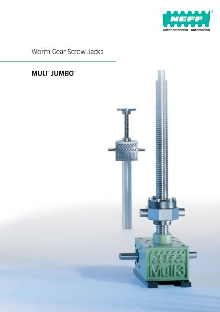
Worm gear screw jacks<br />
MULI ® , JUMBO ® 9<br />
NEFF worm gear screw jacks of<br />
the MULI ® and JUMBO ® series<br />
are manufactured for loads<br />
from 5 to 500kN. All models are<br />
designed for both pushing and<br />
pulling forces, and for positionindependent<br />
functioning.<br />
The cubic housing, standardised<br />
mounting material and endpieces,<br />
and pre-drilled flange<br />
holes permit the ideal installation<br />
of motor, gears and shaft<br />
encoder.<br />
Synchronisation of several<br />
worm gear screw jacks is simple<br />
with the complete range of<br />
accessories.
Overview of NEFF worm gear screw jacks<br />
Design versions<br />
Axially translating<br />
screw<br />
Version N or V<br />
The rotary motion of precision<br />
worm gearing (worm shaft and<br />
internally threaded worm wheel)<br />
is converted into axial linear<br />
motion of the screw, which<br />
travels/translates through the<br />
gear box housing. The load is<br />
attached to the end of the<br />
screw.<br />
➄<br />
➁<br />
➂a<br />
➂b<br />
➀<br />
➃<br />
➀<br />
➁<br />
➂a<br />
Functional Design<br />
The cubic housing with its predrilled<br />
flange holes makes for<br />
simple mounting, and allows<br />
longer power-on times.<br />
Because the heat is more<br />
efficiently dissipated, ensuring<br />
longer lubricant lifetimes.<br />
Lubrication of the<br />
Worm Wheel<br />
Radial lubrication holes in the<br />
worm wheel grease the<br />
trapezoidal screw. The<br />
resultant lower friction and<br />
warming lead to an increased<br />
lifetime, especially in the case<br />
of longer strokes.<br />
Heavy Duty Bearings<br />
Radial deep-groove ball bearings<br />
(Muli ® 1–3) and conical<br />
roller bearings (Muli ® 4+5 and<br />
JUMBO ® 1–5) on the screw shaft<br />
make it possible to handle<br />
heavy loads. Axial ball bearings<br />
as the main pressure bearings<br />
(for all sizes) give a large safety<br />
margin, and increase the overall<br />
lifetime.<br />
10
Rotating screw<br />
Version R<br />
<strong>Drive</strong>n by a precision worm<br />
gearing (screw keyed to the<br />
worm wheel), the rotary motion<br />
of the screw is translated into<br />
linear motion of the travelling<br />
nut on the screw.<br />
➄<br />
➂a<br />
➂b<br />
➀<br />
➃<br />
➂b<br />
➃<br />
➄<br />
Heavy Duty Bearings<br />
Radial deep-groove ball bearings<br />
(Muli ® 1–3) and conical<br />
roller bearings (Muli ® 4+5 and<br />
JUMBO ® 1–5) on the screw shaft<br />
make it possible to handle<br />
heavy loads. Axial ball bearings<br />
as the main pressure bearings<br />
(for all sizes) give a large safety<br />
margin, and increase the overall<br />
lifetime.<br />
Central Lubrication<br />
The worm gear screw jack is<br />
conveniently lubricated at one<br />
point. Maintenance – whether<br />
manual or automatic – is child’s<br />
play.<br />
Housing Material<br />
The housing in aluminium<br />
(Muli ® 1+2) or highly stable<br />
spheroidal graphite cast iron<br />
(Muli ® 3 and higher) provides<br />
more stability, especially at<br />
higher temperatures. This<br />
provides a safety margin,<br />
even under rugged conditions.<br />
11
MULI ® , JUMBO ®<br />
General technical data<br />
The range includes a total of<br />
ten worm gear screw jack<br />
models in two series: MULI a 1<br />
to MULI a 5 with lifting capacities<br />
up to 100 kN and<br />
JUMBO a 1 to JUMBO a 5 with<br />
lifting capacities from 150 kN<br />
to 500 kN statically.<br />
Speed of travel<br />
Gear Ratio H (high speed)<br />
Worm gear screw jacks with<br />
trapezoidal screw produce an<br />
advance of 1 mm for each full<br />
revolution of the worm shaft.<br />
That is, the linear speed is<br />
1500 mm per min at 1500 rpm.<br />
Worm gear screw jacks with ball<br />
screws achieve between<br />
1071 mm per min and 2124 mm<br />
per min, depending on size and<br />
lead.<br />
Gear Ratio (low speed)<br />
Worm gear screw jacks with<br />
trapezoidal screw produce an<br />
advance of 0.25 mm for each<br />
full revolution of the worm<br />
shaft. That is, the linear speed is<br />
375 mm per min at 1500 rpm.<br />
Worm gear screw jacks with ball<br />
screws achieve between 312 mm<br />
per min and 535 mm per min,<br />
depending on size and lead.<br />
Please note that higher speeds<br />
of travel can be achieved with<br />
larger screw pitches or multiple<br />
start screws. The worm gear<br />
screw jack’s maximum drive<br />
revs of 1500 rpm must not<br />
be exceeded.<br />
The higher efficiency of the<br />
ball screw drive also permits a<br />
longer duty cycle.<br />
Tolerances and<br />
backlash<br />
■<br />
The gearbox housings are<br />
machined on the four mounting<br />
sides. The tolerances<br />
conform to DIN ISO 2768-mH.<br />
The sides that are not machined<br />
(the cooling ribs) conform<br />
to DIN 1688-T1/GTA 16<br />
for MULI ® 1+2, DIN 1685,<br />
GTB 18 – GGG-40 from MULI ® 3.<br />
■<br />
■<br />
■<br />
■<br />
The axial backlash of the jack<br />
screw under alternating load<br />
is as follows:<br />
–Trapezoidal screws:<br />
up to 0.4 mm (to DIN 103)<br />
– Ball screws: 0.08 mm.<br />
The lateral play between the<br />
outside diameter of the screw<br />
and the guide diameter is<br />
0.2 mm.<br />
The backlash in the worm<br />
gears is ± 4 ° for gear ratio L<br />
and ± 1 ° for gear ratio H.<br />
Trapezoidal screws are manufactured<br />
to a straightness of<br />
0.3 – 1.5 mm/m, ball screws to<br />
a straightness of 0.08 mm/m<br />
over a length of 1000 mm<br />
and to the following pitch<br />
accuracies:<br />
MULI a 1–MULI a 5:<br />
0.05 mm/300 mm length<br />
JUMBO a 1–JUMBO a 5:<br />
0.2 mm/300 mm length.<br />
Lateral forces on the jack<br />
screw.<br />
Any lateral forces that may<br />
occur should be taken by an<br />
external guide rail.<br />
Stop collar A<br />
Prevents the screw from being<br />
removed from the jack gearbox.<br />
Fitted as standard on ball screw<br />
versions N and V. Optionally<br />
available for screw jacks with<br />
trapezoidal screws.<br />
The stop collar cannot be used<br />
as a fixed stop.<br />
Self-locking<br />
The self-locking function<br />
depends on a variety of parameters:<br />
■<br />
Large pitches<br />
■<br />
Different gear ratios<br />
■<br />
Lubrication<br />
■<br />
Friction parameters<br />
■<br />
Ambient influences, such as<br />
high or low temperatures,<br />
vibrations, etc.<br />
■<br />
The mounting position<br />
Versions with ball screw and<br />
TGS/KGS with large pitches are<br />
consequently not self-locking.<br />
Suitable brakes or braking<br />
motors must therefore be considered<br />
in such cases. Limited<br />
self-locking is available for<br />
smaller pitches (single-start).<br />
Self locking in individual cases<br />
on demand.<br />
Special versions<br />
In addition to the extensive<br />
standard range, NEFF can also<br />
supply anticlockwise, multi-start<br />
and special material worm gear<br />
screw jacks on request. Please<br />
ask our product managers.<br />
12
MULI ® , JUMBO ®<br />
General technical data<br />
Trapezoidal srews<br />
MULI 1 MULI 2 MULI 3 MULI 4 MULI 5 JUMBO 1 JUMBO 2 JUMBO 3 JUMBO 4 JUMBO 5<br />
Maximum lifting capacity [kN] 1) 5 10 25 50 100 150 200 250 350 500<br />
Screw diameter and pitch [mm] 18 x 4 20 x 4 30 x 6 40 x 7 55 x 9 60 x 9 70 x 10 80 x 10 100 x 10 120 x 14<br />
Stroke in mm per full turn Ratio H 2) 1 1 1 1 1 1 1 1 1 1<br />
of the worm shaft [mm] Ratio L 2) 0.25 0.25 0.25 0.25 0.25 0.25 0.25 0.25 0.25 0.25<br />
Gear ratio Ratio H 2) 4:1 4:1 6:1 7:1 9:1 9:1 10:1 10:1 10:1 14:1<br />
Ratio L 2) 16:1 16:1 24:1 28:1 36:1 36:1 40:1 40:1 40:1 56:1<br />
Efficiency [%] 3) Ratio H 2) 31 29 29 26 24 23 22 20 19 19<br />
Ratio L 2) 25 23 23 21 19 18 17 15 15 15<br />
Weight [kg] (zero stroke) 1,2 2,1 6 17 32 41 57 57 85 160<br />
Weight [kg per 100 mm stroke] 0.26 0.42 1.14 1.67 3.04 3.1 4.45 6.13 7.9 11.5<br />
Idling torque [Nm] H 0.04 0.11 0.15 0.35 0.84 0.88 1.28 1.32 1.62 1.98<br />
L 0.03 0.10 0.12 0.25 0.51 0.57 0.92 0.97 1.10 1.42<br />
Housing material G – AL GGG – 40<br />
Ball screws<br />
MULI 1 MULI 2 MULI 3 MULI 4 MULI 5 JUMBO 3<br />
Maximum lifting capacity [kN] 1) 5 10 12.5 22 42 65 78<br />
Screw diameter and pitch [mm] 1605 2005 2505 4005 4010 5010 8010<br />
Stroke in mm per full turn Ratio H 2) 1.25 1.25 0.83 0.71 1.43 1.1 1<br />
of the worm shaft [mm] Ratio L 2) 0.31 0.31 0.21 0.18 0.36 0.28 0.25<br />
Gear ratio Ratio H 2) 4:1 4:1 6:1 7:1 9:1 10:1<br />
Ratio L 2) 16:1 16:1 24:1 28:1 36:1 40:1<br />
Efficiency [%] 3) Ratio H 2) 57 56 55 53 56 47 45<br />
Ratio L 2) 46 44 43 43 45 37 34<br />
Weight [kg] (zero stroke) 1.3 2.3 7 19 35 63<br />
Weight [kg per 100 mm stroke] 0.26 0.42 1.14 1.67 3.04 6.13<br />
Idling torque [Nm] H 0.04 0.11 0.15 0.35 0.84 1.32<br />
L 0.03 0.10 0.12 0.25 0.51 0.97<br />
Housing material G – AL GGG – 40<br />
Note:<br />
Initial breakaway torque:<br />
approx. 2 – 3 times nominal<br />
torque in run-up (FU operation!)<br />
1) Dependent on speed of stroke,<br />
power-on time, etc. (see p. 12)<br />
Order-Code see page 55<br />
2) H=high travel speed,<br />
L=low travel speed.<br />
3) The specified efficiency values are<br />
average values.<br />
13
MULI ® , JUMBO ®<br />
Dimensions, versions N, V<br />
Effective stroke + C1<br />
D6 (4x per side)<br />
Grease nipple<br />
If attachments are to be fitted, please specify on which side (A/B)!<br />
Size<br />
Dimensions [mm]<br />
A1 1) A2 A3 a1 a2 B1 B2 B3 B4 b1 b2 b3 b4 b5 C1 C2 C3 2)<br />
MULI 1 80 25 24 60 10 24 72 120 77 52 18 3 13 1.5 20 62 35(46)<br />
MULI 2 100 32 28 78 11 27.5 85 140 90 63 20 5 15 1.5 30 75 45(48.5)<br />
MULI 3 130 45 31 106 12 45 105 195 110 81 36 5 15 2 30 82 50<br />
MULI 4 180 63 39 150 15 47.5 145 240 150 115 36 6 16 2 45 117 65<br />
MULI 5 200 71 46 166 17 67.5 165 300 170 131 56 8 30 2.5 55 160 95<br />
JUMBO 1 210 71 49 170 20 65 195 325 200 155 56 8 40 8 55 175 95<br />
JUMBO 2 240 80 60 190 25 67.5 220 355 225 170 56 8 45 8 55 165 110<br />
JUMBO 3 240 80 60 190 25 67.5 220 355 225 170 56 8 45 8 55 165 110<br />
JUMBO 4 290 100 65 230 30 65 250 380 255 190 56 10 54 8 65 220 140<br />
JUMBO 5 360 135 75 290 35 100 300 500 305 230 90 14 80 8 90 266 200<br />
Size<br />
Dimensions [mm]<br />
C4 3) C5 C6 D1k6 4) D2 5) D3 6) D4Tr D4KGT D5 3) D6 D7H7 D8 D9xb6 7) R (TK) 7) V-KGT 5)<br />
MULI 1 12(23) 19 31 10 x 21.5 32 M12 x 1.75 Tr18 x 4 1605 29.6(48) M8 28 12 M5 x 8 32 (45.25) 30 x 30<br />
MULI 2 18(21.5) 20 37.5 14 x 25 40 M14 x 2.0 Tr20 x 4 2005 38.7(61) M8 35 15 M6 x 9 35 (49.5) 40 x 40<br />
MULI 3 23 22 41 16 x 42.5 50 M20 x 2.5 Tr30 x 6 2505 46 M10 35 17 M8 x 10 44 (62.2) 50 x 50<br />
MULI 4 32 29 58.5 20 x 45 60 M30 x 3.5 Tr40 x 7 4005/4010 60 M12 52 25 M10 x 14 55 (77.8) 60 x 60<br />
MULI 5 40 48 80 25 x 65 82 M36 x 4 Tr55 x 9 5010 85 M20 52 28 M12 x 16 60 (84.85) 80 x 80<br />
JUMBO 1 40 48 87.5 25 x 62.5 90 M48 x 2 Tr60 x 9 – 90 M24 52 28 M12 x 16 60 (84.85) –<br />
JUMBO 2 40 58 82.5 30 x 65 115 M56 x 2 Tr70 x 10 – 105 M30 58 32 M12 x 18 (80) –<br />
JUMBO 3 40 58 82.5 30 x 65 115 M64 x 3 Tr80 x 10 8010 120 M30 58 32 M12 x 18 (80) 120 x 120<br />
JUMBO 4 50 78 110 35 x 62.5 133 M72 x 3 Tr100 x 10 – 145 M36 72 40 M16 x 30 (100) –<br />
JUMBO 5 60 118 133 48 x 97.5 153 M100 x 3 Tr120 x 14 – 170 M42 80 50 M16 x 40 (115) –<br />
Note:<br />
Subject to change without notice.<br />
1) Dimension A1 for MULI 1 + 2 to<br />
DIN 1688-T1/GTA 16, from MULI 3 to<br />
DIN 1685 GTB 18.<br />
Order-Code see page 55<br />
2) This dimension refers to the closed<br />
height and represents a minimum.<br />
It must be increased if bellows are<br />
used (see page 22).<br />
3) The values in brackets refer to<br />
version with ball screw.<br />
4) Diameter and length to shoulder.<br />
5) Square tube for version with ball<br />
screw and anti-rotation device.<br />
6) In accordance to DIN 13 screw thread:<br />
MULI.<br />
In accordance to DIN 13 fine pitch<br />
thread: JUMBO.<br />
7) JUMBO 2 – 5 only 3 holes.<br />
14
MULI ® , JUMBO ®<br />
Dimensions, versions R<br />
Effective<br />
stroke<br />
D6 (4x per side)<br />
Grease nipple<br />
If attachments are to be fitted, please specify on which side (A/B)!<br />
Please specify direction of flanged side!<br />
Size<br />
Dimensions [mm]<br />
A1 1) A2 A3 a1 a2 B1 B2 B3 B4 b1 b2 b3 b4 b5 C1 C2 C3 C4 C6<br />
MULI 1 80 25 24 60 10 24 72 120 77 52 18 3 13 1.5 12 62 15 12 31<br />
MULI 2 100 32 28 78 11 27.5 85 140 90 63 20 5 15 1.5 15 75 20 18 37.5<br />
MULI 3 130 45 31 106 12 45 105 195 110 81 36 5 15 2 20 82 25 23 41<br />
MULI 4 180 63 39 150 15 47.5 145 240 150 115 36 6 16 2 25 117 30 32 58.5<br />
MULI 5 200 71 46 166 17 67.5 165 300 170 131 56 8 30 2.5 25 160 45 40 80<br />
JUMBO 1 210 71 49 170 20 65 195 325 200 155 56 8 40 8 25 175 55 40 87.5<br />
JUMBO 2 240 80 60 190 25 67.5 220 355 225 170 56 8 45 8 25 165 70 40 82.5<br />
JUMBO 3 240 80 60 190 25 67.5 220 355 225 170 56 8 45 8 25 165 75 40 82.5<br />
JUMBO 4 290 100 65 230 30 65 250 380 255 190 56 10 54 8 25 220 100 50 110<br />
JUMBO 5 360 135 75 290 35 100 300 500 305 230 90 14 80 8 30 266 120 60 133<br />
Size<br />
Dimensions [mm]<br />
D1k6 2) D2j6 D4TR D4KGT D5 D6 D7H7 D8 D9xb6 R (TK) 5) E1 3) E2 3) F1 3) 4) F2 3) 4) F3 3) 4) F43) 4)<br />
MULI 1 10 x 21.5 12 Tr18 x 4 1605 29.6 M8 28 12 M5 x 8 32 (45.25) 12/12 44/44 48/48 28/28 38/38 6/5.5<br />
MULI 2 14 x 25 15 Tr20 x 4 2005 38.7 M8 35 15 M6 x 9 35 (49.5) 12/12 44/44 55/55 32/32 45/45 7/7<br />
MULI 3 16 x 42.5 20 Tr30 x 6 2505 46 M10 35 17 M8 x 10 44 (62.2) 14/14 46/46 62/62 38/38 50/50 7/7<br />
MULI 4 20 x 45 25 Tr40 x 7 4005/4010 60 M12 52 25 M10 x 14 55 (77.8) 16/16 73/59 95/80 63/53 78/68 9/7<br />
MULI 5 25 x 65 40 Tr55 x 9 5010 85 M20 52 28 M12 x 16 60 (84.85) 18/18 97/97 110/110 72/72 90/90 11/11<br />
JUMBO 1 25 x 62.5 45 Tr60 x 9 – 90 M24 52 28 M12 x 16 60 (84.85) 20 99 125 85 105 11<br />
JUMBO 2 30 x 65 55 Tr70 x 10 – 105 M30 58 32 M12 x 18 (80) 30 100 180 95 140 17<br />
JUMBO 3 30 x 65 60 Tr80 x 10 8010 120 M30 58 32 M12 x 18 (80) 30/22 110/101 190/145 105/105 150/125 17/14<br />
JUMBO 4 35 x 62.5 80 Tr100 x 10 – 145 M36 72 40 M16 x 30 (100) 35 130 240 130 185 25<br />
JUMBO 5 48 x 97.5 95 Tr120 x 14 – 170 M42 80 50 M16 x 40 (115) 40 160 300 160 230 28<br />
Note:<br />
Subject to change without notice.<br />
1) Dimension A1 for MULI 1 + 2 to<br />
DIN 1688-T1/GTA 16, from MULI 3 to<br />
DIN 1685 GTB 18.<br />
Order-Code see page 55<br />
2) Diameter and length to shoulder.<br />
3) The first values in the table apply to<br />
the trapezoidal screw nut EFM. For<br />
dimension 4010 the first values in the<br />
table are valid.<br />
4) The second values in the table apply<br />
to the ball screw nut KGF.<br />
5) JUMBO 2 – 5 only 3 holes.<br />
15
Accessories MULI ® , JUMBO ®<br />
Trapezoidal nuts<br />
Complete bronze nut<br />
EFM<br />
For drive units in continuous<br />
operation with particularly good<br />
wear properties. Can be used as<br />
safety nut; “sea water resistant”<br />
in combination with stainless<br />
screws. EFM nuts have the<br />
same dimensions as ball nuts<br />
KGF-N and can therefore be<br />
fitted together with the nut<br />
mountings KON-N and KAR-N.<br />
Material:<br />
G-CuSn 7 ZnPg (Rg 7)<br />
∂B = 269 N/mm 2 ; HB 10 = 75<br />
Size Type/Size Dimensions [mm]<br />
D1h9 D4 D5 6xD6 L1 L2 L3 L4 L5<br />
MULI 1 EFM Tr 18 x 4 28 48 38 6 44 12 8 15 20<br />
MULI 2 EFM Tr 20 x 4 32 55 45 7 44 12 8 15 20<br />
MULI 3 EFM Tr 30 x 6 38 62 50 7 46 14 8 20 25<br />
MULI 4 EFM Tr 40 x 7 63 95 78 9 73 16 10 20 25<br />
MULI 5 EFM Tr 55 x 9 72 110 90 11 97 18 10 20 25<br />
JUMBO 1 EFM Tr 60 x 9 85 125 105 11 99 20 10 20 25<br />
JUMBO 2 EFM Tr 70 x 10 95 180 140 17 100 30 16 20 25<br />
JUMBO 3 EFM Tr 80 x 10 105 190 150 17 110 30 16 20 25<br />
JUMBO 4 EFM Tr 100 x 10 130 240 185 25 130 35 16 25 30<br />
JUMBO 5 EFM Tr 120 x 14 160 300 230 28 160 40 20 30 35<br />
Adapter for attachment<br />
of the second<br />
bellows<br />
Version R only<br />
Order-Code see page 55<br />
16
Accessories MULI ® , JUMBO ®<br />
Ball nuts<br />
Flanged ball nut KGF<br />
Flanged ball screw nut with<br />
mounting and lubrication holes<br />
and with profiled gaskets<br />
(reduces lubricant leakage and<br />
prevents ingress of dirt particles)<br />
for ball screw KGS.<br />
Material: 1.7131 (ESP 65).<br />
Note:<br />
For KSG version, please specify<br />
installation direction of nut.<br />
Zero-backlash units<br />
KGT-FF/KGT-MM/KGT-FM<br />
Factory adjusted and assembled<br />
combinations of two cylindrical<br />
nuts (MM), two flanged nuts<br />
(FF) or one flanged and one<br />
cylindrical nut (FM). Only available<br />
as screw mechanism, i.e.<br />
nut preassembled on the<br />
corresponding ball screw.<br />
Size Type/ Dimensions [mm] Axial No. Load rating [kN]<br />
Diameter [mm]/ backlash of<br />
Lead [mm]/ D1 D4 D5 D6 L1 L2 L4 L5 L7 L9 L10 G max. circuits C 1) C 2) Co =Coa<br />
[mm]<br />
MULI 1 KGF-N 1605 RH-EE 3) 28 38 5.5 48 8 44 15 20 12 8 6 M6 0.08 3 12.0 9.3 13.1<br />
MULI 2 KGF-N 2005 RH-EE 3) 32 45 7 55 8 44 15 20 12 8 6 M6 0.08 3 14.0 10.5 16.6<br />
MULI 3 KGF-N 2505 RH-EE 3) 38 50 7 62 8 46 20 25 14 8 7 M6 0.08 3 15.0 12.3 22.5<br />
MULI 4 KGF-N 4005 RH-EE 3) 53 68 7 80 10 59 20 25 16 8 8 M6 0.08 5 26.0 23.8 63.1<br />
MULI 4 KGF-N 4010 RH-EE 3) 63 78 9 95 10 73 20 25 16 8 8 M8x1 0.08 3 50.0 38.0 69.1<br />
MULI 5 KGF-N 5010 RH-EE 3) 72 90 11 110 10 97 20 25 18 8 9 M8x1 0.08 5 78.0 68.7 155.8<br />
JUMBO 3 KGF-N 8010 RH-EE 3) 105 125 14 145 10 101 20 25 22 8 11 M8x1 0.08 5 93.0 86.2 262.4<br />
1) Dynamic load rating to DIN 69051<br />
Part 4, draft version 1978.<br />
2) Dynamic load rating to DIN 69051<br />
Part 4, draft version 1989.<br />
3) EE = rubber wiper<br />
Adapter for attachment<br />
of the second<br />
bellow<br />
Version R only<br />
Order-Code see page 55<br />
17
Accessories MULI ® , JUMBO ®<br />
Mountings<br />
Mounting feet L<br />
Supplied loose with mounting<br />
bolts for jack. Burnished.<br />
Muli 1 + 2 with version N-KGT<br />
not on side F. Standard: side E.<br />
(see page 14/15)<br />
Size Dimensions [mm] Weight<br />
A1 A2 A3 A4 A5 A6 A7 A8 [kg]<br />
L MULI 1 72 52 8.5 20 100 120 10 10 0.3<br />
L MULI 2 85 63 8.5 20 120 140 10 10 0.4<br />
L MULI 3 105 81 11 24 150 170 10 12 0.8<br />
L MULI 4 145 115 13.5 30 204 230 13 16 1.7<br />
L MULI 5 171 131 22 40 236 270 17 25 3.9<br />
L JUMBO 1 205 155 26 50 250 290 20 30 5.8<br />
L JUMBO 2 230 170 32 65 290 340 25 40 10<br />
L JUMBO 3 230 170 32 65 290 340 25 40 10<br />
L JUMBO 4 270 190 39 80 350 410 30 50 20.8<br />
L JUMBO 5 330 230 45 100 430 500 35 60 34.4<br />
Trunnion mountings K<br />
Supplied loose with mounting<br />
bolts for jack. Burnished.<br />
Standard: side E.<br />
Side F please specify.<br />
(see page 14/15)<br />
Size Dimensions [mm] Weight<br />
L1 L2 L3 L4 L5 L6 Df8 D1 D2 B [kg]<br />
K MULI 1 110 80 49 9 72 13 15 44 18 20 0.76<br />
K MULI 2 140 100 60 10 85 18 20 58 23 25 1.44<br />
K MULI 3 170 130 76 11 105 18 25 72 28 30 2.80<br />
K MULI 4 240 180 102 12 145 28 35 86 38 40 7.40<br />
K MULI 5 270 200 117 17 165 33 45 115 48 50 10.72<br />
K JUMBO 1 290 210 120 15 195 38 50 130 56 60 11.8<br />
K JUMBO 2 330 240 140 20 220 43 70 170 76 80 26.1<br />
K JUMBO 3 330 240 140 20 220 43 70 170 76 80 26.1<br />
K JUMBO 4 410 290 165 20 250 58 80 160 88 90 40.2<br />
K JUMBO 5 520 360 210 30 300 78 90 175 96 100 67.7<br />
18
Accessories MULI ® , JUMBO ®<br />
Mountings<br />
Universal joint adapter<br />
KAR<br />
Universal joint adapter for trunnion<br />
mounting of flanged ball<br />
nut KGF and flanged trapezoidal<br />
nut EFM.<br />
Material:<br />
1.0065 (St37) or 1.0507 (St52)<br />
Size Type Dimensions [mm] Weight<br />
for KGF for EFM A2 B1 B2 B3 C1 D1 D4 G x T [kg]<br />
KAR MULI 1 KAR 1605 Tr 16x4/Tr 18x4 12 70 50 10 20 28 38 M5x10 0.20<br />
KAR MULI 2 KAR 2005 Tr 20x4/Tr 24x4 16 85 58 13.5 25 32 45 M6x12 0.30<br />
KAR MULI 3 KAR 2505 Tr 30x6 18 95 65 15 25 38 50 M6x12 0.50<br />
KAR MULI 4 KAR 4005 25 125 85 20 30 53 68 M6x12 1.20<br />
KAR 4010 Tr 40x7 30 140 100 20 40 63 78 M8x14 2.50<br />
KAR MULI 5 KAR 5010 Tr 55x9 40 165 115 25 50 72 90 M10x16 2.80<br />
KAR JUMBO 1 KAR 6310 Tr 60x9 40 180 130 25 50 85 105 M10x16 3.30<br />
KAR JUMBO 3 KAR 8010 50 200 150 25 60 105 125 M12x18 4.80<br />
Adapter bracket KON<br />
Adapter bracket for the radial<br />
fixing of flanged ball nut KGF.<br />
Material:<br />
1.0065 (St37) or 1.0507 (St52)<br />
Type for KGF<br />
Dimensions [mm]<br />
A1 A2 max 1) A2 min B1 B2 C1 C2 C4 1) D1 D4 G x T<br />
KON 1605 60 35 25 50 34 40 24 M 8x15 28 38 M 5x10<br />
KON 2005 68 37.5 29 58 39 40 24 M 8x15 32 45 M 6x12<br />
KON 2020/2050 75 42.5 32.5 65 49 40 24 M 10x15 35 50 M 6x12<br />
KON 2505 75 42.5 32.5 65 49 40 24 M 10x15 38 50 M 6x12<br />
KON 3205 82 45 37 75 54 50 30 M 10x12 45 58 M 6x12<br />
KON 3210/3240/4005 92 50 42 85 60 50 30 M 12x15 53 68 M 6x12<br />
KON 4010 120 70 50 100 76 65 41 M 14x25 63 78 M 8x14<br />
KON 5010 135 77.5 57.5 115 91 88 64 M 16x25 72 90 M 10x16<br />
KON 6310 152 87.5 65 130 101 88 64 M 16x30 85 105 M 10x16<br />
1) Standard = A2 max (delivery status)<br />
19
Accessories MULI ® , JUMBO ®<br />
Attachments<br />
Top plate BP<br />
Screwed onto the mounting<br />
thread of the jack screw and<br />
protected against rotation.<br />
Standard: Hole-pattern BP symmetrically<br />
to SHG housing.<br />
Note: Please specify alignment<br />
at version V.<br />
Size Dimensions [mm] Weight<br />
B1 B2 ø B3 B4 B5 B6 B7x4 B8 [kg]<br />
BP MULI 1 20 7 65 48 29.3 M12 9 M5 0.2<br />
BP MULI 2 21 8 80 60 38.7 M14 11 M6 0.3<br />
BP MULI 3 23 10 90 67 46 M20 11 M8 0.6<br />
BP MULI 4 30 15 110 85 60 M30 13 M8 1.2<br />
BP MULI 5 50 20 150 117 85 M36 17 M10 4.8<br />
BP JUMBO 1 50 25 170 130 90 M48x2 21 M10 5<br />
BP JUMBO 2 60 30 200 155 105 M56x2 25 M12 7.7<br />
BP JUMBO 3 60 30 220 170 120 M64x3 25 M12 9.8<br />
BP JUMBO 4 80 40 260 205 145 M72x3 32 M12 18.4<br />
BP JUMBO 5 120 40 310 240 170 M100x3 38 M12 29.6<br />
Fork end GA<br />
Screwed onto the mounting<br />
thread of the jack screw and<br />
protected against rotation.<br />
Supplied with split pins and<br />
collar pins. Galvanized.<br />
Standard: Collar pin mounted<br />
parallel to the drive shaft.<br />
Note: Please specify alignment<br />
at version V.<br />
Size Dimensions [mm] Weight<br />
G2 G3 G4H9 G5 ❋ G6B12 G7 G8 G9 G10 G11 [kg]<br />
GA MULI 1 48 24 12 24 12 M5 M12 18 62 20 0.15<br />
GA MULI 2 56 28 14 28 14 M6 M14 22 72 24.5 0.2<br />
GA MULI 3 80 40 20 40 20 M8 M20 30 105 34 0.8<br />
GA MULI 4 120 60 30 60 30 M8 M30 43 160 52 2.5<br />
GA MULI 5 144 72 35 70 35 M10 M36 54 188 60 3.8<br />
20
Accessories MULI ® , JUMBO ®<br />
Attachments<br />
Clevis end GK<br />
Screwed onto the mounting<br />
thread of the jack screw and<br />
protected against rotation.<br />
Standard: Collar pin mounted<br />
parallel to the drive shaft.<br />
Note: Please specify alignment<br />
at version V.<br />
Size Dimensions [mm] Weight<br />
G1 G2 G3 G4H8 G6H10 G7 G8 G9 [kg]<br />
GK MULI 1 55 40 15 10 15 30 M12 M5 0.2<br />
GK MULI 2 63 45 18 12 20 39 M14 M6 0.3<br />
GK MULI 3 78 53 20 16 30 45 M20 M8 0.6<br />
GK MULI 4 100 70 30 20 35 60 M30 M8 1.2<br />
GK MULI 5 130 97 33 22 40 85 M36 M10 2.5<br />
GK JUMBO 1 120 75 45 40 60 90 M48x2 M10 4.8<br />
GK JUMBO 2 130 90 50 50 70 105 M56x2 M12 4.8<br />
GK JUMBO 3 155 105 60 60 80 120 M64x3 M12 8.0<br />
GK JUMBO 4 220 135 85 80 110 145 M72x3 M12 22.5<br />
GK JUMBO 5 300 200 100 90 120 170 M100x3 M12 31.5<br />
21
Accessories MULI ® , JUMBO ®<br />
Protection<br />
Bellows F<br />
Bellow cover for protection<br />
against external influences.<br />
Suitable for horizontal or vertical<br />
installation.<br />
Material: PVC-coated polyester,<br />
stitched construction.<br />
Temperature range -30 °C to<br />
70 °C.<br />
Calculation: For each 150 mm<br />
of open length up to 1.80 m<br />
allow 8 mm when calculating<br />
the closed length. Allow 10 mm<br />
for each 150 mm over 1.80 m.<br />
The calculated length is added<br />
to value C3 (see page 14) as the<br />
screw extension.<br />
Diameter F2 may differ on the<br />
opposite side, depending on<br />
the attachment fitted.<br />
Installation:<br />
Installation position must be<br />
specified: horizontal installation<br />
requires internal support washers;<br />
in the case of vertical installation,<br />
bellows over 2 m have<br />
textile strips. Attachment is by<br />
hose clamps.<br />
Note: Version R (rotating screw)<br />
includes two bellows with bellows<br />
holder (please specify<br />
installation details for second<br />
bellows, see pp. 14/15). The<br />
attachment of the second bellows<br />
at the end of the screw is<br />
carried out by the customer.<br />
Please always specify the flange<br />
direction of the nut.<br />
Spiral spring covers SF<br />
Available on request (refer also<br />
to the catalogue Screw <strong>Drive</strong>s<br />
page 30/31).<br />
to 1800 mm:<br />
Fmin = 2 · F1 + rounding ( stroke 150 ) · 8 [mm]<br />
to 1800 mm:<br />
Fmin = 2 · F1 + rounding ( stroke 150 ) · 10 [mm]<br />
Fmax = Fmin + stroke<br />
Size<br />
Dimensions [mm]<br />
For design F1 F2 F3 F4<br />
F MULI 1 N/V TGS 1) 12 30 30 101<br />
N/V KGS 1) 12 48 30 101<br />
R 12 30 28 101<br />
F MULI 2 N/V TGS 1) 12 39 39 113<br />
N/V KGS 1) 12 61 39 113<br />
R 12 39 32 113<br />
F MULI 3 N/V 20 46 46 127<br />
R 20 46 38 127<br />
F MULI 4 N/V 20 60 60 140<br />
R TGS/KGS-4010 20 60 63 140<br />
R KGS-4005 20 60 53 140<br />
F MULI 5 N/V 20 85 85 152<br />
R 20 85 72 152<br />
F JUMBO 1 N/V 20 90 90 165<br />
R 20 90 85 165<br />
F JUMBO 2 N/V 20 105 105 175<br />
R 20 105 95 175<br />
F JUMBO 3 N/V 20 120 120 191<br />
R 20 120 105 191<br />
F JUMBO 4 N/V 20 145 145 201<br />
R 20 145 130 201<br />
F JUMBO 5 N/V 20 170 170 245<br />
1) TGS = Trapezoidal screw<br />
KGS = Ball srew<br />
R 20 170 160 245<br />
22
Accessories MULI ® , JUMBO ®<br />
Protection<br />
Limit switches with<br />
roller lever ES<br />
Particularly suitable for endposition<br />
shutoff.<br />
Actuating cam 30° in accordance<br />
with DIN 69639:<br />
A (Minimum actuating stroke):<br />
2.6 ± 0.5 mm<br />
B (Differential stroke):<br />
0.85 ± 0.25 mm<br />
FO (Minimum switch-on force):<br />
1N<br />
Ve (Approach velocity):<br />
0.001 to 0.1 m/s<br />
Connection:<br />
5-core cable with PVC sheath,<br />
1m long<br />
Conductor cross-section<br />
0.75 mm 2<br />
Brown/blue: NO contact<br />
Black/black: NC contact<br />
Green/yellow: PE conductor<br />
Switching capacity: NFC 63146<br />
(IEC 947-5-1)<br />
Limit switch installation<br />
position<br />
Standard installation side B (see<br />
Fig.).<br />
Note: If installation on other<br />
side, please specify<br />
Limit switch,<br />
fixed<br />
Limit switch,<br />
adjustable<br />
(Universal joint adapter)<br />
(Universal joint adapter)<br />
switch 1<br />
L = stroke 1 + G 1<br />
switch 1<br />
L = stroke 1 + G 2<br />
switch 2<br />
switch 2<br />
Size<br />
Dimensions [mm]<br />
A1 A2 B C ø D E F G1 G2 K<br />
MULI 1 40 65 30 80 80 20 25 82 107 20<br />
MULI 2 45 70 30 80 80 20 25 87 112 25<br />
MULI 3 50 75 30 80 90 20 25 92 117 30<br />
MULI 4 60 85 30 80 100 20 25 102 127 40<br />
MULI 5 70 95 30 80 120 20 25 112 137 50<br />
JUMBO 1 80 105 30 80 140 20 25 122 147 60<br />
JUMBO 2 100 125 30 80 160 20 25 142 167 80<br />
JUMBO 3 100 125 30 80 160 20 25 142 167 80<br />
JUMBO 4 110 135 30 80 170 20 25 152 177 90<br />
JUMBO 5 120 145 30 80 190 20 25 162 187 100<br />
23
Loading a wing for final<br />
assembly at Airbus S.E.S.<br />
in Toulouse, France.<br />
.
<strong>Drive</strong> <strong>technology</strong><br />
Worm gear screw jacks and electric drive from<br />
a single source – what do you get out of it?<br />
Motors and motor adapter<br />
flanges from NEFF complement<br />
the MULI ® and JUMBO ®<br />
worm gear screw jacks to<br />
produce powerful drive<br />
packages that can be put to<br />
use quickly and without<br />
complications. They are<br />
intended to have 3-phase<br />
motors attached as standard.<br />
<strong>Drive</strong> <strong>technology</strong> from<br />
NEFF – Your benefit:<br />
Optimum price-performance<br />
ratio<br />
System application, screw jack<br />
and drive all perfectly matched –<br />
everything from a single source.<br />
No hidden costs<br />
Calculation, planning, choice of<br />
components and parameterization<br />
are all handled by NEFF.<br />
One contact<br />
For all drive questions from calculation<br />
up to maintenance and<br />
service you have one responsible<br />
competent partner.<br />
Note<br />
The offering presented here is<br />
the standard program for the<br />
German market. As a rule, the<br />
international NEFF partners have<br />
a different range of motors and<br />
gears.<br />
25
<strong>Drive</strong> <strong>technology</strong><br />
Motor adapter flanges<br />
Motor adapter flanges<br />
MG<br />
Motor adapter flanges are used<br />
to mount motors to worm gear<br />
screw jacks and house the coupling<br />
for connecting the motor<br />
to the drive shaft.<br />
When ordering, please specify<br />
the side to which the motor<br />
adapter flange is to be attached<br />
(A or B)<br />
Size Motor Design Dimensions [mm]<br />
MG/ZF 1) A B C D E ø F F H I K<br />
MG MULI 1 DFT71 MG 120 80 65 22 28 77 81.5 80 10<br />
MG MULI 1 DFT80 MG 120 80 56 22 28 62 91.5 90 10<br />
MG MULI 2 DFT71 MG 120 80 65 26 35 77 81.5 80 10<br />
MG MULI 2 DFT80 MG 120 80 78 26 35 88 92.5 91 10<br />
MG MULI 2 DFT90 MG 160 110 90 31 35 110 109.5 108 15<br />
MG MULI 3 DFT71 MG 120 80 77 28 35 87 91.5 90 10<br />
MG MULI 3 DFT80 MG 120 80 78 28 35 88 103 101 10<br />
MG MULI 3 DFT90 MG 160 110 95 28 35 104 125 123 12<br />
MG MULI 3 DFV100/112 MG + ZF 200 130 100 24 35 145 133 131 29<br />
MG MULI 4 DFT80 MG 120 80 75 42 52 – 88 105 103 12<br />
MG MULI 4 DFT90 MG 160 110 98 42 52 114 118 116 15<br />
MG MULI 4 DFV100/112 MG + ZF 200 130 120 30 52 145 134 131 29<br />
MG MULI 5 DFT90 MG 160 110 105 45 52 120 138.5 136 15<br />
MG MULI 5 DFV100/112 MG 200 130 125 35 52 145 154 152 16<br />
1) MG = Motor adapter flange<br />
ZF = Intermediate flange<br />
26
<strong>Drive</strong> <strong>technology</strong><br />
Motor adapter flanges<br />
Motor adapter flanges<br />
MG<br />
Intermediate flange ZF<br />
Additional<br />
flange for<br />
MULI3/MULI4<br />
C200<br />
Dimensions [mm] Coupling Coupling half 1) Coupling half 1)<br />
L M N R1 R2 S1 S2 T U Size MULI Motor<br />
72 3.5 20 70.7 32 100 45.3 6.6 5.5 RA19 RA19 ø10 RA19 ø14<br />
85 3.5 20 70.7 32 100 45.3 6.6 5.5 RA19 RA19 ø10 RA19 ø19<br />
73 3.5 22 70.7 35 100 49.5 6.6 6.6 RA19 RA19 ø14 RA19 ø14<br />
84 3.5 22 70.7 35 100 49.5 6.6 6.6 RA19 RA19 ø14 RA19 ø19<br />
100 4 27 92 35 130 49.5 9 6.6 RA24 RA24 ø14 RA24 ø24<br />
83 3.5 27 70.7 44 100 62.2 6.6 9 RA19 RA19 ø16 RA19 ø14<br />
93 3.5 32 70.7 44 100 62.2 6.6 9 RA19 RA19 ø16 RA19 ø19<br />
114 4 30 92 44 130 62.2 9 9 RA24 RA24 ø16 RA24 ø24<br />
119 4.5 40 116.7 44 165 62.2 M10 9 RA28 RA28 ø16 RA28 ø28<br />
94 3.5 35 70.7 55 100 78 6.6 11 RA24 RA24 ø20 RA24 ø19<br />
106 4 30 92 55 130 78 M8 11 RA24 RA24 ø20 RA24 ø24<br />
119 4.5 38 116.7 55 165 78 M10 11 RA28 RA28 ø20 RA28 ø28<br />
122 4 48 92 60 130 85 M8 13.5 RA28 RA28 ø25 RA28 ø24<br />
138 7 50 116.7 60 165 85 M10 13.5 RA28 RA28 ø25 RA28 ø28<br />
1) When ordering, specify explicitly the<br />
diameter of the hole drilling in the<br />
motor side of the coupling half.<br />
27
<strong>Drive</strong> <strong>technology</strong><br />
3-phase motors<br />
3-phase motors M<br />
3-phase 4-pole motors<br />
(1500 rpm) in totally enclosed<br />
fan-cooled designs in accordance<br />
with VDE 0530 Part 1.<br />
Standard degree of protection:<br />
IP55. Temperature class F. Other<br />
SEW motors on request.<br />
Notes: If the free shaft end of<br />
the motor is used as shaft for a<br />
slip-on emergency hand wheel,<br />
a device will be required witch<br />
interrupts the power supply<br />
before the crank engages.<br />
Motors with different speeds<br />
and brake on request.<br />
Flange shape<br />
u<br />
t<br />
a1<br />
d<br />
b1<br />
d<br />
k<br />
i 2 k 0<br />
g<br />
f 1 c 1<br />
1<br />
x x9<br />
l 2<br />
y<br />
l 11<br />
l 12 l 1<br />
l 14 l 13 u 1<br />
d1<br />
g<br />
s1<br />
t1<br />
e 1<br />
p2<br />
st<br />
p<br />
l<br />
Foot shape<br />
k<br />
x<br />
x 9<br />
c<br />
h<br />
y<br />
p2<br />
ød<br />
g<br />
g 2<br />
m 1<br />
øs<br />
w 1<br />
n<br />
b<br />
w 2<br />
a<br />
f<br />
e<br />
Performance data<br />
Size Nominal Nominal Power Nominal Rel. locked- Nominal Rel. locked- Rel. Run- Rotor inertia Rotor inertia Braking<br />
power speed factor current at rotor cur- moment rotor torque up moment JMot JBremsmot moment<br />
[kW] [rpm] cos ϕ 400 V [A] rent IA/IN [Nm] MA/MN MH/MN [10 -4 kgm 2 ] [10 -4 kgm 2 ] [Nm]<br />
DT71K4 0.15 1380 0.67 0.61 2.9 1.0 1.8 1.7 4.6 5.5 5.0<br />
DT71C4 0.25 1380 0.70 0.80 2.8 1.7 1.8 1.7 4.6 5.5 5.0<br />
DT71D4 0.37 1380 0.76 1.15 3.0 2.6 1.8 1.7 4.6 5.5 5.0<br />
DT80K4 0.55 1360 0.72 1.75 3.4 3.9 2.1 1.8 7.5 7.5 10<br />
DT80N4 0.75 1380 0.73 2.1 3.8 5.2 2.2 2.0 8.7 9.6 10<br />
DT90S4 1.1 1400 0.77 2.8 4.3 7.5 2.0 1.9 25 31 20<br />
DT90L4 1.5 1410 0.78 3.55 5.3 10.2 2.6 2.3 34 40 20<br />
DV100M4 2.2 1410 0.83 4.7 5.9 15.0 2.7 2.3 53 59 40<br />
DV100L4 3.0 1400 0.83 6.3 5.6 20.5 2.7 2.2 65 71 40<br />
DV112M4 4.0 1420 0.84 8.7 5.4 26.9 2.4 2.1 98 110 55<br />
28
<strong>Drive</strong> <strong>technology</strong><br />
3-phase motors<br />
Dimensions<br />
The values in brackets refer to<br />
motors with brake.<br />
Flange shape<br />
Size<br />
Dimensions [mm]<br />
a1 b1 c1 d d1 e1 f1 g g1 i2 k k0 I I11<br />
DFT71K4 120 80 8 14 11 100 3 145 122(127) 24 232 (296) 208 (296) 30 4<br />
DFT71C4 120 80 8 14 11 100 3 145 122(127) 24 232 (296) 208 (272) 30 4<br />
DFT71D4 120 80 8 14 11 100 3 145 122(127) 24 232 (296) 208 (272) 30 4<br />
DFT80K4 120 80 8 19 14 100 3 145 122(127) 34 292 (356) 258 (322) 40 4<br />
DFT80N4 120 80 8 19 14 100 3 145 122(127) 34 292 (356) 258 (322) 40 4<br />
DFT90S4 160 110 10 24 19 130 3.5 197 154(161) 53.5 323 (408) 273 (358) 50 5<br />
DFT90L4 160 110 10 24 19 130 3.5 197 154(161) 53.5 323 (408) 273 (358) 50 5<br />
DFV100M4 200 130 10 28 19 165 3.5 197 166 60 371 (456) 311 (396) 60 5<br />
DFV100L4 200 130 10 28 19 165 3.5 197 166 60 401 (486) 341 (426) 60 5<br />
DFV112M4 200 130 11 28 24 165 3.5 221 179(182) 64 409 (489) 345 (425) 60 5<br />
Size<br />
Dimensions [mm]<br />
I12 l1 l2 l13 l14 s1 t u t1 u1 x x9 y p2<br />
DFT71K4 22 23 24 1 20 6.6 16 5 12.5 4 87 (127) 61 (86) 97 50<br />
DFT71C4 22 23 24 1 20 6.6 16 5 12.5 4 87 (127) 61 (86) 97 50<br />
DFT71D4 22 23 24 1 20 6.6 16 5 12.5 4 87 (127) 61 (86) 97 50<br />
DFT80K4 32 30 31 4 22 6.6 21.5 6 16 5 87 (127) 61 (86) 97 50<br />
DFT80N4 32 30 31 4 22 6.6 21.5 6 16 5 87 (127) 61 (86) 97 50<br />
DFT90S4 40 40 42 4 32 9 27 8 21.5 6 87 (127) 76 (121) 97 50<br />
DFT90L4 40 40 42 4 32 9 27 8 21.5 6 87 (127) 76 (121) 97 50<br />
DFV100M4 50 40 42 4 32 11 31 8 21.5 6 106 (139) 74 (125) 109 56<br />
DFV100L4 50 40 42 4 32 11 31 8 21.5 6 106 (139) 74 (125) 109 56<br />
DFV112M4 50 50 55 5 40 11 31 8 27 8 106 (139) 91 (131) 109 56<br />
Foot shape<br />
Size<br />
Dimensions [mm]<br />
a b c e f h m1 n s w1 w2<br />
DT71K4 90 112 5 115 144 71 32 31 7 45 75<br />
DT71C4 90 112 5 115 144 71 32 31 7 45 75<br />
DT71D4 90 112 5 115 144 71 32 31 7 45 75<br />
DT80K4 100 125 10 125 149 80 28 33 9 50 90<br />
DT80N4 100 125 10 125 149 80 28 33 9 50 90<br />
DT90S4 125 140 8 152 176 90 32 32 9 56 106<br />
DT90L4 125 140 8 152 176 90 32 32 9 56 106<br />
DV100M4 140 160 12 170 188 100 35 38 12 63 123<br />
DV100L4 140 160 12 170 188 100 35 38 12 63 123<br />
DV112M4 140 190 14 170 220 112 35 44 12 70 130<br />
29
<strong>Drive</strong> <strong>technology</strong><br />
Couplings<br />
Flexible couplings<br />
RA, RG<br />
Flexible couplings transmit the<br />
torque by positive locking, and<br />
compensate for slight nonalignment,<br />
stagger and offset<br />
of shafts.<br />
Standard toothed ring 92<br />
Shore A.<br />
Version 1<br />
Version 1a<br />
Size Ver- max. Dimensions [mm] Offsets Locking Weight<br />
sion torque max. max. radial ∆ Kw [°] screw<br />
axial- non-alignment max. angle stagger<br />
stagger n=1500 rpm at n=1500 rpm Dim. Dim.<br />
[Nm] A1 E F B b D1 D d Cmin 1) Cmax 1) ∆ Ka [mm] ∆ Kr [mm] ∆ Kw [mm] G t [kg]<br />
RA 14 1a 7.5 35 – 11 13 10 – 30 10 6 15 1.0 0.17 1.2 0.67 M4 5 0.05<br />
RA 19 1 10 66 20 25 16 12 32 40 18 10 19 1.2 0.20 1.2 0.82 M5 10 0.15<br />
RA 19 1a 10 66 – 25 16 12 – 41 18 19 24 1.2 0.20 1.2 0.82 M5 10 0.15<br />
RA 24 1 35 78 24 30 18 14 40 55 27 14 24 1.4 0.22 0.9 0.85 M5 10 0.25<br />
RA 24 1a 35 78 – 30 18 14 – 56 27 22 28 1.4 0.22 0.9 0.85 M5 10 0.35<br />
RA 28 1 95 90 28 35 20 15 48 65 30 14 28 1.5 0.25 0.9 1.05 M6 15 0.40<br />
RA 28 1a 95 90 – 35 20 15 – 67 30 28 38 1.5 0.25 0.9 1.05 M6 15 0.55<br />
RG 38 1 190 114 37 45 24 18 66 80 38 16 38 1.8 0.28 1.0 1.35 M8 15 0.85<br />
RG 42 1 265 126 40 50 26 20 75 95 46 28 42 2.0 0.32 1.0 1.70 M8 20 1.2<br />
RG 48 1 310 140 45 56 28 21 85 105 51 28 48 2.1 0.36 1.1 2.00 M8 20 1.7<br />
RG 55 1 410 160 52 65 30 22 98 120 60 30 55 2.2 0.38 1.1 2.30 M10 20 7.3<br />
RG 65 1 625 185 61 75 35 26 115 135 68 40 65 2.6 0.42 1.2 2.70 M10 20 11.0<br />
RG 75 1 975 210 69 85 40 30 135 160 80 40 75 3.0 0.48 1.2 3.30 M10 25 17.9<br />
RG 90 1 2400 245 81 100 45 34 160 200 100 50 90 3.4 0.50 1.2 4.30 M12 30 28.5<br />
1) This catalogue does not list all<br />
intermediate sizes. Further sizes<br />
on request.<br />
Offsets<br />
In the case of the standard and<br />
large hubs RA 14–48, the<br />
tapped hole G for the locking<br />
screw is located opposite the<br />
groove.<br />
Locking screws according to<br />
DIN 916 with toothed washer.<br />
Axialverlagerung offset ∆ Ka∆Ka Radialverlagerung offset ∆ ∆Kr Winkelverlagerung Angular offset ∆Kw ∆ [Grad]<br />
L max. = L + ∆Ka<br />
∆K W [mm] = L max – L min<br />
30
<strong>Drive</strong> <strong>technology</strong><br />
Handwheels<br />
Handwheels HR<br />
2-spoke handwheel of chill-cast<br />
light aluminium RN 9501, polished,<br />
with rotating conical handle<br />
of black plastic. Bore keyed to<br />
DIN 6885.<br />
Size Dimensions [mm] Bore<br />
A D d d1 d2 H7 L1 L l1 l2<br />
HR 80 10 80 31 21 ø10 16 29 50 2.5<br />
HR 80 10 80 31 21 ø14 16 29 50 2.5<br />
HR 100 10 100 33 21 ø10 17 33 50 2.5<br />
HR 100 10 100 33 21 ø14 17 33 50 2.5<br />
HR 125 13 125 35 22 ø10 18 36 56 2.5<br />
HR 125 13 125 35 22 ø14 18 36 56 2.5<br />
HR 140 13 140 37 22 ø14 19 39 56 2.5<br />
HR 140 13 140 37 22 ø16 19 39 56 2.5<br />
HR 160 16 160 40 23 ø14 20 40 65 2.5<br />
HR 160 16 160 40 23 ø16 20 40 65 2.5<br />
HR 200 16 200 45 26 ø16 24 45 80 2.5<br />
HR 200 16 200 45 26 ø20 24 45 80 2.5<br />
HR 250 19 250 52 31 ø20 28 50 102 2.5<br />
HR 250 19 250 52 31 ø25 28 50 102 2.5<br />
31
<strong>Drive</strong> <strong>technology</strong><br />
Pillow blocks<br />
Pillow block UKP<br />
The standard range for housing<br />
bearings with clamping sleeve.<br />
Cast iron housing with surface<br />
painted for protection from<br />
corrosion. The bearing insets in<br />
rolled steel have forged rings,<br />
which prolong the lifetime of<br />
the bearings.<br />
Size Shaft Size Dimensions [mm] Dynamic Static Weight<br />
diam- GX- Load Load<br />
eter shaft rating rating<br />
[mm] L H A1 A J N N1 L1 H1 H2 s1 B D2 G [kN] [kN] [kg]<br />
UKP205H 20 140 36.5 26 38 105 13 19 42 16 70 18.5 35 38 M6x1 14.0 7.88 0.8<br />
UKP206H 25 165 42.9 30 48 121 17 21 54 18 83 20.5 38 45 M6x1 19.5 11.2 1.4<br />
UKP207H 30 1 167 47.6 31 48 127 17 21 54 19 94 22.5 43 52 M6x1 25.7 15.2 1.8<br />
UKP208H 35 184 49.2 34 54 137 17 23 52 19 100 24.5 46 58 M6x1 29.6 18.2 2.2<br />
UKP209H 40 2 190 54.0 37 54 146 17 23 60 20 108 26 50 65 M6x1 31.85 20.8 2.5<br />
UKP210H 45 4 206 57.2 39 60 159 20 25 65 22 114 27.5 55 70 M6x1 35.1 23.2 3.1<br />
UKP211H 50 219 63.5 40 60 171 20 25 70 22 126 29 59 75 M6x1 43.55 29.2 3.7<br />
UKP212H 55 241 69.8 44 70 184 20 25 70 25 138 31 62 80 M6x1 52.5 32.8 5.0<br />
UKP213H 60 8 265 76.2 46 70 203 25 29 77 27 150 32 65 85 M6x1 57.2 40.0 6.1<br />
32
<strong>Drive</strong> <strong>technology</strong><br />
Safety nuts<br />
Safety nut SFM-TGS/<br />
KGS 1)<br />
For version R: The safety nut is<br />
positioned below the travelling<br />
nut without axial load and is<br />
therefore not subjected to wear.<br />
The functioning of the safety<br />
nut is guaranteed only when<br />
installation and applied forces<br />
are as shown in the illustration<br />
(see right). As the travelling nut<br />
wears, the distance “x“ between<br />
the two nuts decreases, which<br />
provides a visual check of wear<br />
without the need for dismantling.<br />
The travelling nut must be<br />
replaced when the axial play on<br />
a single-thread screw is more<br />
that 1 /4 of the lead of the<br />
thread (= dimension X).<br />
Otherwise, safety cannot be<br />
guaranteed.<br />
Wear greater than 1 /4 of the<br />
lead of the thread can endanger<br />
persons and property.<br />
Dimension X must be checked<br />
regularly.<br />
The safety nut supports the<br />
load if the thread form of the<br />
travelling nut fails as a result of<br />
excessive wear (dirt, lubrication<br />
starvation, overheating, etc.).<br />
The safety nut can only be<br />
ordered together with the<br />
flanged nut (we reserve the<br />
right to make design changes).<br />
For version N: The design is<br />
similar to that for version R. A<br />
visual check for wear is also<br />
possible in this case. Please<br />
specify the load direction<br />
when ordering.<br />
Size Dimensions [mm] (see pages 15 and 16 for dimensions of travelling nut) Weight<br />
[kg]<br />
A1 A2-0,5 B1 B2 X<br />
SFM MULI 1 10 28 10 44 1 0.45<br />
SFM MULI 2 10 32 10 44 1 0.55<br />
SFM MULI 3 12 38 10 46 1.5 0.70<br />
SFM MULI 4 16 63 15 73 1.75 3.10<br />
SFM MULI 5 20 72 16 97 2.25 4.30<br />
SFM JUMBO 1 20 85 16 99 2.25 5.70<br />
SFM JUMBO 2 25 95 20 100 2.5 11.30<br />
SFM JUMBO 3 25 105 20 110 2.5 13.70<br />
SFM JUMBO 4 30 130 25 130 2.5 23.30<br />
SFM JUMBO 5 40 160 25 160 3.5 45.70<br />
1) KGS on request.<br />
33
<strong>Drive</strong> <strong>technology</strong><br />
Bevel gear boxes<br />
Bevel gear boxes KRG<br />
The spiral bevel gear boxes<br />
offer numerous advantages<br />
to the designer and have<br />
been specially selected to<br />
complement the NEFF range<br />
of worm gear screw jacks<br />
and accessories. A total of<br />
eight box sizes and accessories<br />
are available as standard.<br />
The gear boxes are fully<br />
machined with tapped holes<br />
for universal mounting, thus<br />
offering six possible mounting<br />
positions.<br />
Housing and Flange:<br />
Version: Cube<br />
Material: Lamellar graphite cast<br />
iron EN-GJL-250 (0.6025) or<br />
spheroidal graphite cast iron<br />
ENGJS- 400-15 (0.7040) or G-Al<br />
Si 10 Mg (0.1645)<br />
Shaft:<br />
Version: Shaft centring according<br />
to DIN 332 Sheet 2, feather<br />
key according to DIN 6885,<br />
Sheet 1<br />
Tolerance: j6 or k6<br />
Material: C 45 (1.0503) or<br />
42 Cr Mo 4 (1.7225)<br />
Hollow shafts:<br />
Version: With keyway or smooth,<br />
with shrink-fit washer<br />
Tolerance: Hole H7<br />
Material: C 45 (1.0503)<br />
Bevel gears:<br />
Version: Klingelnberg Palloid or<br />
Klingelnberg Zyklo-Palloid spiral<br />
teeth, optimised tooth<br />
flanks and profile geometry,<br />
tooth flanks milled, hardened<br />
and lapped<br />
Material: Stainless steel 16 Mn<br />
Cr 5 (1.7131) or 17 Cr Ni<br />
Mo 6 (1.6587)<br />
Shaft-hub connection:<br />
Version: Non-positive or positive<br />
locking, parts are fitted warm<br />
Shaft seal:<br />
Version: With or without dust<br />
scraper according to DIN 3760<br />
Material: NBR or Viton<br />
Bearings:<br />
Version: Conical roller bearings<br />
or roller bearings, depending<br />
on version<br />
Lubricants:<br />
Version: According to DIN 51502<br />
mineral grease or oil,<br />
depending on revs.<br />
Installation position: Please<br />
specify when ordering.<br />
Volume: Depends on installation<br />
position, see Operating<br />
Instructions.<br />
Surface treatment:<br />
Version: Nitro-cellulose base<br />
coat<br />
Colour: RAL 7035 light grey<br />
Noise:<br />
Approx. 75 dB(A) at 1m distance<br />
Lifetime of bearings:<br />
Approx. 20,000 operating hours<br />
Max. permitted gear<br />
temperature:<br />
80° C<br />
Mechanical<br />
Gear size<br />
efficiency η 50 100 – 230 250 – 400<br />
At nominal moment 0.85 ≤η≤0.9 0.9 ≤η≤0.94 0.95 ≤η≤0.96<br />
Type L<br />
Ba 30 Ba 40 Ba 50 Ba 60<br />
Type ML<br />
Ba 30 Ba 40 Ba 50 Ba 60<br />
34
<strong>Drive</strong> <strong>technology</strong><br />
Bevel gear boxes<br />
Dimensions [mm]<br />
Type L 50<br />
Size Gear ratio D1 D2 D3 D7 D11 D12 D13 D21 D22 D23 D31 D32 D33<br />
1 – 2<br />
50 12j6 12j6 12j6 M6 44f7 64,5 54 44f7 64.5 54 44f7 64.5 54<br />
3 + 4<br />
Size Gear ratio L L1 L2 L3 L7 L10 L12 L14 L20 L22 L24<br />
1 – 2 100<br />
50 144 26 26 26 65 42 2 72 42 2<br />
3 + 4 115<br />
Size Gear ratio L30 L32 L34 L71 R Feather key D1 Feather key D2 + D3<br />
1 – 2<br />
50 72 42 2 45 0.8 4 x 4 x 20 4 x 4 x 20<br />
3 + 4<br />
35
<strong>Drive</strong> <strong>technology</strong><br />
Bevel gear boxes<br />
Dimensions [mm]<br />
Type L 100 – 200<br />
Size Gear ratio D1 D2 D3 D7 D8 D11 D12 D13 D21 D31 L L1 L2 L3<br />
1 – 2 18j6 35<br />
100 3 + 4 15j6 18j6 18j6 M8 9 60f7 89f7 75 60f7 60f7 190 30 35 35<br />
5 + 6 12j6 25<br />
1 – 2 25j6 45<br />
200 3 + 4 20j6 25j6 25j6 M10 11 80f7 119f7 100 80f7 80f7 244 40 45 45<br />
5 + 6 15j6 30<br />
Size Gear ratio L7 L10 L12 L14 L20 L22 L24 L30 L32 L34 L71 R Feather key D1 Feather key D2 + D3<br />
1 – 2 122 6 x 6 x 25<br />
100 3 + 4 90 127 55 2 95 55 2 95 55 2 70 1 5 x 5 x 20 6 x 6 x 25<br />
5 + 6 122 4 x 4 x 16<br />
1 – 2 162 8 x 7 x 36<br />
200 3 + 4 120 157 75 2 122 72 3 122 72 3 100 1 6 x 6 x 30 8 x 7 x 36<br />
5 + 6 147 5 x 5 x 20<br />
36
<strong>Drive</strong> <strong>technology</strong><br />
Bevel gear boxes<br />
Dimensions [mm]<br />
Type L 230 – 400<br />
Size Gear ratio D1 D2 D3 D7 D8 D11 D12 D13 D21 D31 L L1 L2 L3<br />
1 – 2 32j6<br />
230 3 + 4 28j6 32j6 32j6 M10 11 95f7 135f7 115 100f7 100f7 274 50 50 50<br />
5 + 6 24j6<br />
1 – 2 35j6 60<br />
250 3 + 4 28j6 35j6 35j6 M12 13.5 110f7 158f7 135 110f7 110f7 320 55 60 60<br />
5 + 6 24j6 50<br />
1 – 2 42j6 80<br />
300 3 + 4 35j6 42j6 42j6 M12 13.5 120f7 198f7 175 120f7 120f7 406 68 80 80<br />
5 + 6 28j6 55<br />
1 – 2 55j6 150f7 90<br />
370 3 + 4 40j6 55j6 55j6 M16 17.5 225f7 200 150f7 150f7 454 80 90 90<br />
140f7<br />
5 + 6 35j6 70<br />
1 – 2 60j6 110<br />
400 3 + 4 50j6 60j6 60j6 M16 17.5 160f7 258f7 230 180f7 180f7 570 110 110<br />
90<br />
5 + 6 45j6<br />
Size Gear ratio L7 L10 L12 L14 L20 L22 L24 L30 L32 L34 L71 R Feather key D1 Feather key D2 + D3<br />
1 – 2 180 10 x 8 x 45<br />
230 3 + 4 140 83 2 137 82 3 137 82 3 110 2 8 x 7 x 40 10 x 8 x 45<br />
195<br />
5 + 6 8 x 7 x 40<br />
1 – 2 212 10 x 8 x 45<br />
250 3 + 4 160 227 95 2 160 95 3 160 95 3 120 2 8 x 7 x 40 10 x 8 x 45<br />
5 + 6 222 8 x 7 x 40<br />
1 – 2 273 3 12 x 8 x 60<br />
300 3 + 4 200 261 120 203 117 3 203 117 3 160 3 10 x 8 x 45 12 x 8 x 60<br />
2<br />
5 + 6 248 8 x 7 x 45<br />
1 – 2 305 16 x 10 x 80<br />
370 3 + 4 230 310 135 2 227 132 3 227 132 3 180 5 12 x 8 x 60 16 x 10 x 80<br />
5 + 6 300 10 x 8 x 50<br />
1 – 2 380 5 18 x 11 x 90<br />
400 3 + 4 260 150 5 285 150 20 285 150 20 220 14 x 9 x 70 18 x 11 x 90<br />
360 10<br />
5 + 6 14 x 9 x 70<br />
37
<strong>Drive</strong> <strong>technology</strong><br />
Bevel gear boxes<br />
Dimensions [mm]<br />
Type ML 50/100/200<br />
Size Gear ratio d G7 b1 e1 a1 a2 s2 l1<br />
9 70 85 75 100 4 x ø7 23<br />
50 1 – 4 11 80 100 90 120 4 x ø7 26<br />
14 95 115 115 140 4 x ø9 33<br />
9 70 85 95 105 4 x ø7 23<br />
11 80 100 95 120 4 x ø7 26<br />
100 1 – 6<br />
14 95 115 115 140 4 x ø9 35<br />
19 110 130 140 160 4 x ø9 45<br />
11 80 100 125 140 4 x ø7 26<br />
14 95 115 125 140 4 x ø9 35<br />
200 1 – 6 19 110 130 140 160 4 x ø9 45<br />
24 110 130 140 160 4 x ø9 55<br />
28 130 165 140 190 4 x ø11 65<br />
Size Gear ratio f1 c1 D16 L15 L16 L17<br />
50 1 – 4 4.5 16 8.5 90 9.5 10<br />
100 1 – 6 5 22 10 125 13 12.5<br />
200 1 – 6 5 25 14 145 15 16.5<br />
38
<strong>Drive</strong> <strong>technology</strong><br />
Bevel gear boxes<br />
Selection of the gear box size<br />
<strong>Drive</strong> Output Size 50 Size 100 Size 200 Size 230<br />
speed revs <strong>Drive</strong> torque<br />
n1 n2 P M2 P M2 P M2 P M2<br />
[rpm] [rpm] [kW] [Nm] [kW] [Nm] [kW] [Nm] [kW] [Nm]<br />
50 50.00 0.09 18 0.26 50 0.68 130 1.05 200<br />
250 1000.00 0.47 18 1.28 49 3.14 120 4.71 180<br />
500 500.00 0.89 17 2.41 46 5.76 110 8.90 170<br />
i = 1.0 1000 1000.00 1.68 16 4.40 42 9.42 90 15.71 150<br />
1500 1500.00 2.20 14 5.81 37 12.88 82 20.42 130<br />
2000 2000.00 2.51 12 6.91 33 12.29 73 25.13 120<br />
3000 3000.00 3.14 10 8.80 28 18.85 60 28.27 90<br />
50 33.33 0.06 18 0.17 50 0.45 130 0.70 200<br />
250 166.67 0.31 18 0.86 49 2.09 120 3.32 190<br />
500 333.33 0.59 17 1.68 48 3.84 110 6.28 180<br />
i = 1.5 1000 666.67 1.12 16 3.07 44 6.98 100 11.17 160<br />
1500 1000.00 1.57 15 4.19 40 9.42 90 15.71 150<br />
2000 1333.33 1.95 14 5.31 38 11.87 85 19.55 140<br />
3000 2000.00 2.51 12 6.91 33 15.29 73 25.13 120<br />
50 25.00 0.05 18 0.13 50 0.34 130 0.52 200<br />
250 125.00 0.24 18 0.64 49 1.64 125 2.49 190<br />
500 250.00 0.47 18 1.26 48 3.14 120 4.71 180<br />
i = 2.0 1000 500.00 0.89 17 2.36 45 5.76 110 8.90 170<br />
1500 750.00 1.26 16 3.38 43 7.85 100 12.57 160<br />
2000 1000.00 1.57 15 4.19 40 9.42 90 15.71 150<br />
3000 1500.00 2.20 14 5.81 37 12.88 82 20.42 130<br />
50 16.67 0.03 16 0.07 40 0.17 95 0.31 175<br />
250 83.33 0.13 15 0.34 39 0.77 88 1.48 170<br />
500 166.67 0.26 15 0.66 38 1.47 84 2.79 160<br />
i = 3.0 1000 333.33 0.49 14 1.29 37 2.62 75 5.24 150<br />
1500 500.00 0.68 13 1.83 35 3.51 67 6.81 130<br />
2000 666.67 0.84 12 2.23 32 4.54 65 8.38 120<br />
3000 1000.00 1.15 11 2.93 28 5.45 52 10.47 100<br />
50 12.50 0.02 15 0.05 38 0.12 95 0.23 175<br />
250 62.50 0.10 15 0.25 38 0.60 92 1.11 170<br />
500 125.00 0.18 14 0.48 37 1.15 88 2.16 165<br />
i = 4.0 1000 250.00 0.34 13 0.92 35 2.09 80 3.93 150<br />
1500 375.00 0.51 13 1.34 34 2.91 74 5.50 140<br />
2000 500.00 0.63 12 1.62 31 3.56 68 6.81 130<br />
3000 750.00 0.86 11 2.28 29 4.71 60 7.85 100<br />
50 10.00 0.04 38 0.10 95 0.18 175<br />
250 50.00 0.19 37 0.48 92 0.89 170<br />
500 100.00 0.37 35 0.92 88 1.68 160<br />
i = 5.0 1000 200.00 0.69 33 1.68 80 2.93 140<br />
1500 300.00 0.94 30 2.29 73 3.77 120<br />
2000 400.00 1.17 28 2.85 68 4.61 110<br />
3000 600.00 1.70 27 3.77 60 6.28 100<br />
50 8.33 0.03 32 0.06 74 0.14 160<br />
250 41.67 0.14 31 0.31 70 0.65 150<br />
500 83.33 0.26 30 0.60 69 1.22 140<br />
i = 6.0 1000 166.67 0.51 29 1.19 68 2.27 130<br />
1500 250.00 0.73 28 1.68 64 3.14 120<br />
2000 333.33 0.94 27 2.09 60 3.84 110<br />
3000 500.00 1.36 26 2.72 52 4.97 95<br />
The nominal torque may be<br />
exceeded by a factor of 1.8 for<br />
short periods.<br />
39
<strong>Drive</strong> <strong>technology</strong><br />
Bevel gear boxes<br />
Selection of the gear box size<br />
<strong>Drive</strong> Output Size 250 Size 300 Size 370 Size 400<br />
speed revs <strong>Drive</strong> torque<br />
n1 n2 P M2 P M2 P M2 P M2<br />
[rpm] [rpm] [kW] [Nm] [kW] [Nm] [kW] [Nm] [kW] [Nm]<br />
50 50.00 1.68 320 3.66 700 6.54 1250 9.16 1750<br />
250 250.00 7.85 300 15.18 580 24.87 950 36.65 1400<br />
500 500.00 14.14 270 26.18 500 41.88 800 62.83 1200<br />
i = 1.0 1000 1000.00 23.04 220 42.93 410 67.02 640 94.24 900<br />
1500 1500.00 28.27 180 54.97 350 81.68 520 116.23 740<br />
2000 2000.00 35.60 170 62.83 300 92.15 440 127.75 610<br />
3000 3000.00 10.84 130 69.11 220 100.52 320 138.22 440<br />
50 33.33 1.12 320 2.44 700 4.54 1300 6.28 1800<br />
250 166.67 5.41 310 10.65 610 19.2 1100 26.18 1500<br />
500 333.33 10.12 290 18.85 540 31.41 900 45.38 1300<br />
i = 1.5 1000 666.67 18.15 260 32.81 470 52.36 750 76.79 1100<br />
1500 1000.00 23.04 220 42.93 410 67.02 640 94.24 900<br />
2000 1333.33 27.92 200 51.66 370 79.58 570 110.30 790<br />
3000 2000.00 35.60 170 62.83 300 92.15 440 127.75 610<br />
50 25.00 0.84 320 1.83 700 3.40 1300 4.71 1800<br />
250 125.00 4.06 310 8.38 640 15.71 1200 20.94 1600<br />
500 250.00 7.85 300 15.18 580 24.87 950 36.65 1400<br />
i = 2.0 1000 500.00 14.14 270 26.18 500 41.88 800 62.83 1200<br />
1500 750.00 19.63 250 35.34 450 54.97 700 78.53 1000<br />
2000 1000.00 23.04 220 42.93 410 67.02 640 94.24 900<br />
3000 1500.00 28.27 180 54.97 350 81.68 520 116.23 740<br />
50 16.67 0.51 290 0.87 500 1.52 870 2.97 1700<br />
250 83.33 2.27 260 4.01 460 7.07 810 12.22 1400<br />
500 166.67 4.19 240 7.33 420 13.09 750 21.82 1250<br />
i = 3.0 1000 333.33 6.98 200 12.57 360 21.64 620 34.21 980<br />
1500 500.00 9.42 180 16.23 310 27.75 530 43.98 840<br />
2000 666.67 11.87 170 19.55 280 33.51 480 53.05 760<br />
3000 1000.00 15.71 150 25.13 240 40.84 390 62.83 600<br />
50 12.50 0.37 280 0.63 480 1.26 960 2.09 1600<br />
250 62.50 1.77 270 2.81 430 5.56 850 9.82 1500<br />
500 125.00 3.14 240 5.24 400 10.21 780 17.67 1350<br />
i = 4.0 1000 250.00 5.50 210 9.42 360 17.28 660 30.10 1150<br />
1500 375.00 7.46 190 12.57 320 23.17 590 38.48 980<br />
2000 500.00 9.16 175 14.66 280 27.23 520 45.55 870<br />
3000 750.00 12.57 160 18.85 240 33.77 430 54.97 700<br />
50 10.00 0.27 260 0.54 520 1.02 970 1.57 1500<br />
250 50.00 1.31 250 2.51 480 4.71 900 7.33 1400<br />
500 100.00 2.41 230 4.71 450 8.48 810 13.61 1300<br />
i = 5.0 1000 200.00 4.19 200 8.38 400 14.66 700 23.04 1100<br />
1500 300.00 5.81 185 11.62 370 19.48 620 29.84 950<br />
2000 400.00 7.54 180 14.24 340 23.46 560 35.60 850<br />
3000 600.00 10.05 160 18.85 300 31.41 500 46.49 740<br />
50 8.33 0.18 210 0.30 340 0.53 610 0.87 1000<br />
250 41.67 0.87 200 1.40 320 2.62 600 4.28 980<br />
500 83.33 1.66 190 2.71 310 5.06 580 7.68 880<br />
i = 6.0 1000 166.67 3.23 185 5.06 290 9.25 530 13.61 780<br />
1500 250.00 4.45 170 7.07 270 12.57 480 17.80 680<br />
2000 333.33 5.58 160 8.73 250 15.01 430 20.94 600<br />
3000 500.00 7.85 150 11.52 220 18.85 360 26.18 500<br />
The nominal torque may be<br />
exceeded by a factor of 1.8 for<br />
short periods.<br />
40
<strong>Drive</strong> <strong>technology</strong><br />
Universal joint shafts<br />
Universal joint shafts<br />
GX<br />
Universal joint shafts are used<br />
to connect several worm gear<br />
screw jacks together. The shafts<br />
attenuate noise, vibrations and<br />
impacts and compensate for<br />
axial, radial and angular errors.<br />
They offer exceptional torsional<br />
rigidity, high temperature and<br />
oil resistance and are particularly<br />
suitable where long lengths<br />
and/or high speeds are a factor.<br />
Elastic universal joint shafts are<br />
maintenance-free; the central<br />
section can be removed radially<br />
(to the side) without axial displacement<br />
of the connected<br />
units.<br />
They are supplied as a length of<br />
tube (dimension L to be specified<br />
by customer) fitted with<br />
coupling assemblies at both<br />
ends. Pillow blocks are generally<br />
not required, except for very<br />
long connections.<br />
For optimum alignment of the<br />
jack gear screws, we recommend<br />
the use of universaljointed<br />
shafts with clamping<br />
sets.<br />
Size Dimensions [mm] Weight<br />
M 1) m1 2) m2 3)<br />
[Nm] A B d2 min d2 max d3 d4 L2 N2 R [kg] [kg/m]<br />
GX 1 10 24 7 10 25 56 56 24 36 30 0.47 1.05<br />
GX 2 30 24 8 14 38 85 88 28 55 40 1.06 1.42<br />
GX 4 60 28 8 16 45 100 100 30 65 45 2.31 1.61<br />
GX 8 120 32 10 20 55 120 125 42 80 60 3.55 2.16<br />
GX 16 240 42 12 22 70 150 155 50 100 70 6.16 2.53<br />
GX 25 370 46 14 22 85 170 175 55 115 85 9.5 3.09<br />
GX 30 550 58 16 28 100 200 205 66 140 100 15.21 3.64<br />
1) Transmittable torque 2) m1 = Weight without central section<br />
3) m2 = Weight of central section per<br />
metre<br />
Universal joint shaft<br />
diagram<br />
as a function of length and<br />
speed.<br />
Speed n<br />
[rpm]<br />
Universal joint shaft size<br />
Length of centre section L<br />
41
<strong>Drive</strong> <strong>technology</strong><br />
Length of the universal joint shaft<br />
for MULI ® with tensioner<br />
MULI ® 1<br />
with DKWN tensioner (10 – 20)<br />
Starting torque of the<br />
tensioning element 1.2 Nm<br />
Center distance A<br />
Length of joint shaft L<br />
MULI ® 2<br />
with DKWN tensioner (14 – 26)<br />
Starting torque of the<br />
tensioning element 2.1 Nm<br />
Center distance A<br />
Length of joint shaft L<br />
MULI ® 3<br />
with DKWN tensioner (16 – 32)<br />
Starting torque of the<br />
tensioning element 4.9 Nm<br />
Center distance A<br />
Length of joint shaft L<br />
MULI ® 4<br />
with DKWN tensioner (20 – 38)<br />
Starting torque of the<br />
tensioning element 9.7 Nm<br />
Center distance A<br />
Length of joint shaft L<br />
MULI ® 5<br />
with DKWN tensioner (25 – 47)<br />
Starting torque of the<br />
tensioning element 16.5 Nm<br />
Center distance A<br />
Length of joint shaft L<br />
42
<strong>Drive</strong> <strong>technology</strong><br />
Connecting shafts<br />
Connecting shafts VW<br />
The Series VW connecting<br />
shafts are rigid shafts with a<br />
key way at each end. For<br />
greater distances and diameters<br />
of axle, some of these shafts<br />
are available as tubular shafts.<br />
The holes in the couplings must<br />
be drilled to fit the diameter of<br />
the shaft.<br />
(Torques see chart “couplings”<br />
on page 30.)<br />
Size<br />
Dimensions [mm]<br />
D C B T<br />
VW 20 20 30 6 3.5<br />
VW 25 25 35 8 4<br />
VW 30 30 40 8 4<br />
VW 35 35 40 10 5<br />
VW 40 40 50 12 5<br />
VW 45 45 50 14 5.5<br />
VW 50 50 70 14 5.5<br />
Connecting shaft<br />
diagram<br />
as a function of length and<br />
speed.<br />
Speed n<br />
[rpm]<br />
Connecting shaft size<br />
Length of centre section L<br />
43
<strong>Drive</strong> sizing<br />
Sizing and selection<br />
The procedure for planning<br />
screw jack systems is<br />
generally as follows:<br />
1. Definition of the speed and<br />
possible mounting positions<br />
of the worm gear screw jacks.<br />
2. Selection of the drive components<br />
(couplings, shafts, bevel<br />
gearboxes, motors) for synchronous<br />
drive of the individual<br />
worm gear screw jacks.<br />
The following criteria are<br />
decisive:<br />
■<br />
Lowest possible loading of<br />
the individual transmission<br />
components. Input of the<br />
entire drive torque via the<br />
teeth of a bevel gearbox<br />
must be avoided in particular.<br />
■<br />
■<br />
As few transmission components<br />
as possible and short<br />
connecting shafts.<br />
Provision for the use of a<br />
torque-limiting coupling to<br />
protect the system.<br />
It is sometimes difficult to show<br />
the direction of rotation of the<br />
individual components in the<br />
drawing. The following method<br />
can generally be used to good<br />
effect:<br />
■<br />
Define the position of the<br />
individual worm gear screw<br />
jacks.<br />
■<br />
Enter the direction of rotation<br />
of each worm gear screw jack<br />
for the “lifting“ motion (the<br />
direction of rotation of a shaft<br />
is shown by an arrow pointing<br />
in the direction of movement<br />
of a point on the upper<br />
side of the shaft).<br />
■<br />
■<br />
Draw the possible position of<br />
the bevel gear boxes.<br />
Determine the direction of<br />
rotation and position of the<br />
bevel gear boxes.<br />
44
<strong>Drive</strong> sizing<br />
Examples for the direction of rotation<br />
Fig. 1<br />
Illustration of direction of<br />
rotation<br />
Fig. 1 Fig. 2<br />
Fig. 2<br />
Direction of rotation of a worm<br />
gear screw jack (N) for “lifting“<br />
motion, top view.<br />
Fig. 3<br />
Jack system with four worm<br />
gear screw jacks and two bevel<br />
gear boxes<br />
Fig. 3<br />
Worm gear screw jack<br />
Bevel gear box<br />
lifting<br />
Universal joint shaft<br />
Coupling<br />
lifting<br />
Fig. 4<br />
Jack system, variant 1:<br />
Different position of drive<br />
motor, but only ratio 1:1<br />
possible.<br />
Fig. 4 Fig. 5<br />
Fig. 5<br />
Jack system, variant 2:<br />
Very economical.<br />
45
<strong>Drive</strong> sizing<br />
Selection of a worm<br />
gear screw jack and<br />
corresponding drive<br />
unit<br />
After selecting the drive unit, it<br />
is important to check whether<br />
the worm gear screw jack or<br />
any transmission components<br />
may be overloaded by the drive<br />
unit (see page 47).<br />
The following points should also<br />
be established:<br />
1. On which side is the motor to<br />
be mounted<br />
2. Direction of rotation of the<br />
jack systems.<br />
Forces and torque<br />
values acting on the<br />
worm gear screw jack<br />
Note:<br />
Forces and torque values can<br />
only be estimated by making<br />
simplified assumptions. The<br />
coefficients of friction of sliding<br />
pairs, and thus the heat which<br />
these generate, and the resultant<br />
service lifetime depend on<br />
load, speed, temperature and<br />
lubrication conditions. Critical<br />
speeds and buckling lengths<br />
depend on the rigidity and<br />
mass of the clamping systems<br />
and machine frames, etc.<br />
Feff = Axial force acting on the<br />
jack screw<br />
FS = Result of all lateral forces<br />
acting on the jack screw<br />
M = Torque of the jack screw<br />
or nut (not applicable in<br />
the case of version V)<br />
VH = Lifting speed<br />
Fax = Axial force acting on drive<br />
shaft<br />
Fr = Radial force acting on<br />
drive shaft<br />
MT = <strong>Drive</strong> torque<br />
nT = <strong>Drive</strong> speed<br />
Hubspindel Jack screw<br />
Antriebswelle <strong>Drive</strong> shaft<br />
(Schneckenwelle)<br />
(worm shaft)<br />
46
<strong>Drive</strong> sizing<br />
Duty cycle and drive<br />
power<br />
In order to limit the heat generated<br />
by friction within a worm<br />
gear screw jack, the lifting force<br />
and lifting speed are limited as<br />
a function of the relative duty<br />
cycle. The maximum permissible<br />
lifting force and lifting speed<br />
can be estimated with the aid<br />
of the following method.<br />
f t ffür t for Ausführung version N; the H: values für Ausführung may be doubled L können for version die L doppelten Werte angenommen werden<br />
1,0<br />
0,9<br />
0,8<br />
0,7<br />
0,6<br />
0,5<br />
0,4<br />
0,3<br />
0,2<br />
MULI 1<br />
MULI 2<br />
MULI 3<br />
MULI 4<br />
MULI 5<br />
JUMBO 1<br />
JUMBO 3<br />
JUMBO 5<br />
Ball screw (all)<br />
KGT (alle)<br />
Feff · VH ≤ Fstroke max · VH max · ft<br />
Feff<br />
VH<br />
is the actual axial force<br />
acting on the jack screw<br />
[kN].<br />
is the lifting speed<br />
[mm/min].<br />
0,1<br />
0,09<br />
0,08<br />
0,07<br />
0,06<br />
0,05<br />
0,04<br />
0,03<br />
10<br />
15 20<br />
30<br />
40 50<br />
60<br />
70 80 90 100%<br />
A<br />
Fstroke maxis the maximum permissible<br />
lifting force [kN]<br />
(see table on page 13).<br />
20<br />
30 40<br />
50 60<br />
70 80<br />
90<br />
100%<br />
A: Relative duty A: Relative cycle based Einschaltdauer on 1 bezogen hour auf 1 h<br />
B: Relative duty B: Relative cycle based Einschaltdauer on 10 bezogen minutes auf 10 min<br />
B<br />
VH max<br />
is the maximum permissible<br />
lifting speed [mm/<br />
min]. It is calculated<br />
from the maximum permissible<br />
speed of the<br />
worm shaft of 1500 rpm<br />
(higher speeds on request)<br />
and the transmission<br />
ratio of the<br />
worm gear screw jack.<br />
VH max. = 1500 mm/min<br />
for the version H gearing<br />
and 375 mm/min<br />
for the version L gearing.<br />
ft<br />
For the ball screw version,<br />
refer to the ratio of the<br />
worm gear screw jack in<br />
mm of stroke per full<br />
turn of the worm shaft<br />
on page 13.<br />
is a temperature factor<br />
which is dependent on<br />
the relative duty factor<br />
based on a period of 10<br />
or 60 minutes at 20 °C.<br />
The values determined here do<br />
not apply for very short reciprocating<br />
strokes. Please consult us<br />
in such cases. ft can be extrapolated<br />
to the left-hand edge of<br />
the graph in the case of very<br />
low relative duty cycles (less<br />
than 10 minutes, e.g. for occasional<br />
positioning operations,<br />
adjustments of levels, etc.). This<br />
yields the following approximate<br />
drive power values in kW with<br />
allowance for the efficiency in<br />
each case.<br />
MULI 1 MULI 2 MULI 3 MULI 4 MULI 5 JUMBO 1 JUMBO 2 JUMBO 3 JUMBO 4 JUMBO 5<br />
Ratio H (TGS 1) ) 0.3 0.55 1.18 2.3 4.7 6.5 8.4 10.9 14.7 19<br />
Ratio L (TGS 1) ) 0.19 0.35 0.75 1.4 3 4.2 5.4 7.3 9.3 12<br />
Ball screws 0.3 0.56 0.95 1.7/3.2 5.9 – – 13.9 – –<br />
1)TGS = Trapezoidal screw<br />
These values are not a criterion<br />
for selecting the drive motor; it<br />
should be selected on the basis<br />
of torque, speed and operating<br />
conditions.<br />
47
<strong>Drive</strong> sizing<br />
Critical buckling force<br />
of a screw jack under<br />
compressive loads<br />
Thin lifting screws may buckle<br />
sideways when subjected to<br />
compressive loads. Before the<br />
permissible compressive force is<br />
defined for the screw, allowance<br />
must be made for safety factors<br />
as appropriate to the installation.<br />
Critical buckling force Fcrit [kN]<br />
Feff<br />
≤ fk · Fcrit · 1/Sk<br />
Feff<br />
fk<br />
Fcrit<br />
Sk<br />
is the actual axial force<br />
(compressive force) acting<br />
on the jack screw [kN].<br />
is a correction factor which<br />
makes allowance for the<br />
type of screw bearing.<br />
Sufficiently rigid mounting<br />
of the worm gear screw jack<br />
is consequently a prerequisite<br />
for cases 2, 3 and 4.<br />
is the critical buckling force<br />
as a function of the unsupported<br />
length L.<br />
is the safety factor and<br />
depends on the application<br />
in question. Values between<br />
3 and 6 are customary in<br />
general mechanical<br />
engineering.<br />
Muli2 KGS-2005 and TGS-Tr20x4<br />
Muli1 KGS-1605 and TGS-Tr18x4<br />
KGS-1605 and TGS-Tr18x4<br />
KGS-2505 and TGS-Tr30x6<br />
KGS-5010 and TGS-Tr55x9<br />
TGS = Trapezoidal screw<br />
KGS= Ball screw<br />
Unsupported length L [mm]<br />
Case 1 Case 2 Case 3 Case 4<br />
fk fk = 0.25 0,25<br />
fk fk = 1 fk = 2.05 2,05<br />
fk = 4<br />
für for kleine small L gilt: L: fk fk --> --› 2<br />
48
<strong>Drive</strong> sizing<br />
Critical speed of jack<br />
screws<br />
(Version R only)<br />
Resonant bending vibration may<br />
develop with thin screws rotating<br />
at high speed. Assuming a<br />
sufficiently rigid assembly, the<br />
resonant frequency can be estimated<br />
with the aid of the following<br />
method.<br />
Theoretical critical speed ncrit [rpm]<br />
Speed limit<br />
nperm = fkr · ncrit · 0.8<br />
nperm is the maximum permissible<br />
screw speed [rpm].<br />
fkr<br />
is a correction factor which<br />
makes allowance for the<br />
type of screw bearing.<br />
Sufficiently rigid mounting<br />
of the worm gear screw<br />
jack and bearing is consequently<br />
a prerequisite for<br />
cases 2, 3 and 4.<br />
ncrit<br />
is the critical screw speed;<br />
it corresponds to the basic<br />
bending vibration of the<br />
screw and leads to resonance<br />
effects.<br />
TGS = Trapezoidal screw<br />
KGS= Ball screw<br />
Unsupported length L [mm]<br />
Worm gear screw jacks with<br />
multi-start screws are also available<br />
for applications with high<br />
lifting speeds. These versions<br />
run at a considerably lower screw<br />
speed and better efficiency for<br />
the same lifting speed. They are<br />
generally not self-locking.<br />
Case 1 Case 2 Case 3 Case 4<br />
fkr = 0.36 0,36 fkr = 1 fkr = 1.47 1,47<br />
fkr = 2.23 2,23<br />
49
<strong>Drive</strong> sizing<br />
Required drive torque<br />
of a worm gear screw<br />
jack<br />
The required drive torque of a<br />
worm gear screw jack is governed<br />
by the axial load acting<br />
on the jack screw, the transmission<br />
ratio and the efficiency. It<br />
should be noted that the breakaway<br />
torque may be considerably<br />
higher than the torque required<br />
for continuous running.<br />
This applies in particular to worm<br />
gear screw jacks with low efficiency<br />
after a long standstill<br />
period. The acceleration torque<br />
should be checked if necessary<br />
in cases with large screw pitches<br />
and very short run-up times.<br />
Feff p<br />
MT = · + Mo<br />
2 · π · η i<br />
MT<br />
Feff<br />
η<br />
p<br />
i<br />
is the required drive torque<br />
of the worm gear screw<br />
drive at the worm shaft<br />
[Nm].<br />
is the actual force acting<br />
on the jack screw [kN].<br />
is the efficiency of the<br />
worm gear screw jack in<br />
decimal notiation, e.g. 0.32<br />
instead of 32% (for values,<br />
see table on page 13). η is<br />
an average value determined<br />
by measurement.<br />
is the transmission ratio of<br />
the worm gear screw drive<br />
in mm stroke length per<br />
revolution of the worm<br />
shaft.<br />
Mo<br />
is the idle torque of the<br />
worm gear screw drive<br />
[Nm]. Mo is determined by<br />
measurements undertaken<br />
after a brief running-in<br />
period with liquid grease<br />
lubrication at room temperature.<br />
It represents an average<br />
value which may vary to<br />
a greater or lesser extent,<br />
depending on the runningin<br />
state, lubricant and temperature.<br />
For values, see<br />
table on page 13.<br />
Required drive torque<br />
for a worm gear screw<br />
jack system<br />
The required drive torque for a<br />
worm gear screw jack system is<br />
governed by the drive torque<br />
values for the individual jacks<br />
with allowance for the static<br />
and dynamic frictional losses in<br />
transmission components (coupling,<br />
universal joint shafts, pillow<br />
blocks, angle gear boxes,<br />
etc.). It is useful to draw a diagram<br />
illustrating the flow of<br />
forces.<br />
Example (simplified interpretation)<br />
1<br />
Mdrive motor = MT SHG1 · +<br />
+ MT SHG2 +<br />
Universal joint shaft V1<br />
ηV1<br />
Universal joint shaft V2<br />
Bevel gear box K<br />
1 1<br />
+ MT SHG3 · ·<br />
ηV2<br />
ηK<br />
MT SHG1 is the required drive<br />
torque for the worm<br />
gear screw jack SHG 1.<br />
It should be noted that<br />
the start-up torque<br />
(breakaway torque and<br />
possibly acceleration<br />
torque) may be considerably<br />
higher than the<br />
torque required for continuous<br />
running. This<br />
applies in particular to<br />
worm gear screw jacks<br />
with low efficiency after<br />
a long standstill period.<br />
ηv1<br />
ηv2<br />
ηv<br />
(V1) includes the static and<br />
dynamic frictional losses in<br />
the pillow blocks and couplings.<br />
is the efficiency of connecting<br />
shaft V2<br />
= 0,75...0,95 depending on<br />
the length of the shaft and<br />
number of pillow blocks.<br />
ηK<br />
is the efficiency of the<br />
bevel gear box (only for<br />
the force flow via the<br />
toothing, i.e. between<br />
connecting shaft V2 and<br />
the drive motor).<br />
ηK = 0.90<br />
50
<strong>Drive</strong> sizing<br />
Maximum drive torque<br />
If the worm gear screw jack<br />
jams as a result of the screw<br />
coming into contact with an<br />
obstacle, the toothing can still<br />
absorb the following maximum<br />
torque values MT at the drive<br />
shaft.<br />
In the case of screw jacks connected<br />
in series, the screw jack<br />
closest to the drive can absorb<br />
this torque at its drive shaft.<br />
Size<br />
MULI 1 3.4<br />
MULI 2 7.1<br />
MULI 3 18<br />
MULI 4 38<br />
MULI 5 93<br />
JUMBO 1 148<br />
JUMBO 2 178<br />
JUMBO 3 240<br />
JUMBO 4 340<br />
JUMBO 5 570<br />
MT max [Nm]<br />
Acceleration values<br />
Rotary current asynchronous<br />
motor, 4-pole:<br />
■<br />
Approx. 0.5 m/s 2 (when<br />
switched on directly)<br />
Servo motor:<br />
■<br />
Max. 5 m/s 2 (limited by max.<br />
drive torque).<br />
When using gear jacks in conjunction<br />
with servo motors,<br />
note that:<br />
■<br />
Greater masses are moved,<br />
compared with linear axes.<br />
■<br />
Predominantly, constant<br />
speeds with different revs<br />
are used.<br />
■<br />
Use is often in the area of<br />
the adjustment/positioning<br />
of equipment.<br />
■<br />
Positions with comparatively<br />
short power-on times are<br />
travelled to, and high acceleration<br />
values are therefore<br />
less frequently called for.<br />
■<br />
High acceleration values<br />
have only a negligible effect<br />
on the overall stroke time,<br />
because of the low stroke<br />
speeds.<br />
Forces and torque<br />
values acting on the<br />
drive shaft<br />
If worm gear screw jacks are<br />
not driven free of lateral forces<br />
by means of a coupling connected<br />
to the motor shaft, but<br />
are instead driven by chains or<br />
belts, care must be taken to<br />
ensure that the radial force acting<br />
on the drive shaft does not<br />
exeed the limit values (see<br />
below).<br />
In the worst case due to deflection<br />
through the radial force FR<br />
the worm shaft will lift off of<br />
the worm wheel. This must be<br />
avoided, since it impairs the<br />
engagement between worm<br />
shaft and worm wheel and<br />
leads to higher wear.<br />
Size<br />
MULI 1 0.1<br />
MULI 2 0.2<br />
MULI 3 0.3<br />
MULI 4 0.5<br />
MULI 5 0.8<br />
JUMBO 1 0.8<br />
JUMBO 2 1.3<br />
JUMBO 3 1.3<br />
JUMBO 4 2.1<br />
JUMBO 5 3.1<br />
FR max [kN]<br />
Selection of drive<br />
motor<br />
A suitable drive motor can be<br />
selected when the required<br />
drive torque and drive speed<br />
are known. After selecting a<br />
drive motor, check that it will<br />
not overload any of the worm<br />
gear screw jacks or transmission<br />
components. This risk may occur,<br />
in particular, in installations with<br />
several screw jacks if they are<br />
loaded unevenly. It will generally<br />
be necessary to install limit<br />
switches or torque-limiting couplings<br />
to protect the installation<br />
against impacting against end<br />
positions and obstacles.<br />
Forces and torque<br />
values on the motor<br />
shaft<br />
Toothed-belt or chain drives<br />
may exert considerable radial<br />
forces on the motor shaft if a<br />
very small sprocket is used.<br />
Please consult the motor manufacturer<br />
in cases of doubt.<br />
Selection of a bevel<br />
gear box<br />
Selection of a bevel gearbox is<br />
governed by the following factors:<br />
■<br />
■<br />
■<br />
■<br />
<strong>Drive</strong> torque<br />
<strong>Drive</strong> speed<br />
(see dimensional tables)<br />
Duty cycle and drive power<br />
Forces and torque values<br />
acting on the ends of the<br />
shaft (please consult us in<br />
cases of doubt)<br />
Required drive speed<br />
The required drive speed is<br />
governed by the desired lifting<br />
speed, the transmission ratio of<br />
the jack and the transmission<br />
ratio of the other transmission<br />
components. A particular lifting<br />
speed can normally be achieved<br />
in several ways. Correct selection<br />
depends on the following<br />
criteria:<br />
■<br />
■<br />
■<br />
Favourable efficiency<br />
Minimum load on transmission<br />
components in order to<br />
achieve compact, low-cost<br />
design<br />
Avoiding critical speeds for<br />
jack screws and connecting<br />
shafts.<br />
Jack screw nut torques<br />
The nut torque (M) of the jack<br />
screw is the torque that the<br />
jack screw exerts on the mounting<br />
plate (all N versions except<br />
V), or the torque that the screw<br />
applies to the travelling nut (R<br />
Version). It is not to be confused<br />
with the dirve torque<br />
(MT) of the screw jack gears on<br />
the worm shaft.<br />
M [Nm] = Feff [kN] · fM<br />
(applicable in the areas of<br />
moderate and high loads)<br />
M<br />
Feff<br />
fM<br />
is the jack screw nut<br />
torque [Nm] for the “Lift<br />
under Load“ movement.<br />
is the actual supported<br />
axial force [kN].<br />
is a conversion factor that<br />
accounts for screw geometry<br />
and friction. The value is<br />
applicable under normal<br />
lubrication conditions. The<br />
higher value needs to be<br />
used for dry friction and<br />
static friction. In the case of<br />
ball screw drives, fM is practically<br />
constant.<br />
Size fM fM<br />
(trapezoidal)(ball screw)<br />
MULI 1 1.6 1.6<br />
MULI 2 1.8 1.6<br />
MULI 3 2.7 1.6<br />
MULI 4 3.4 1.6/3.2<br />
MULI 5 4.6 3.2<br />
JUMBO 1 5.5 –<br />
JUMBO 2 6.4 –<br />
JUMBO 3 7.2 3.2<br />
JUMBO 4 8.0 –<br />
JUMBO 5 10.6 –<br />
51
Performance tables for<br />
MULI ® worm gear screw jacks<br />
MULI ® 1–MULI ® 5 with gear ratio<br />
H and L with single-start trapezoidal<br />
screw and 20% duty cycle<br />
per hour at a normal temperature<br />
of 20 °C.<br />
The screw jacks can overheat<br />
or an excessive area pressure<br />
develop in the screw thread at<br />
the speeds stated in the shaded<br />
fields. NEFF cannot assume<br />
any liability for this range.<br />
MULI ® 1 – screw Tr 18 x 4<br />
Speed Lifting Lifting force [kN]<br />
[rmp] speed 5 4 3 2 1,5 1<br />
[m/min] H L H L H L H L H L H L<br />
H L [Nm] [kW] [Nm] [kW] [Nm] [kW] [Nm] [kW] [Nm] [kW] [Nm] [kW] [Nm] [kW] [Nm] [kW] [Nm] [kW] [Nm] [kW] [Nm] [kW] [Nm] [kW]<br />
1500 1.500 0.375 2.61 0.41 0.83 0.13 2.09 0.33 0.67 0.10 1.58 0.25 0.51 0.08 1.07 0.17 0.35 0.05 0.81 0.13 0.27 0.04 0.55 0.09 0.19 0.03<br />
1000 1.000 0.250 2.61 0.27 0.83 0.09 2.09 0.22 0.67 0.07 1.58 0.17 0.51 0.05 1.07 0.11 0.35 0.04 0.81 0.08 0.27 0.03 0.55 0.06 0.15 0.02<br />
750 0.750 0.187 2.61 0.20 0.83 0.06 2.09 0.16 0.67 0.05 1.58 0.12 0.51 0.04 1.07 0.08 0.35 0.03 0.81 0.06 0.27 0.02 0.55 0.04 0.19 0.01<br />
500 0.500 0.125 2.61 0.14 0.83 0.04 2.09 0.11 0.67 0.03 1.58 0.08 0.51 0.03 1.07 0.06 0.35 0.02 0.81 0.04 0.27 0.01 0.55 0.03 0.19 0.01<br />
MULI ® 2 – screw Tr 20 x 4<br />
Speed Lifting Lifting force [kN]<br />
[rmp] speed 10 7,5 5 4 3 2<br />
[m/min] H L H L H L H L H L H L<br />
H L [Nm] [kW] [Nm] [kW] [Nm] [kW] [Nm] [kW] [Nm] [kW] [Nm] [kW] [Nm] [kW] [Nm] [kW] [Nm] [kW] [Nm] [kW] [Nm] [kW] [Nm] [kW]<br />
1500 1.500 0.375 5.60 0.88 1.83 0.29 4.23 0.66 1.40 0.22 2.86 0.45 0.97 0.15 2.31 0.36 0.79 0.12 1.76 0.28 0.62 0.10 1.21 0.19 0.45 0.07<br />
1000 1.000 0.250 5.60 0.59 1.83 0.19 4.23 0.44 1.40 0.15 2.86 0.30 0.97 0.10 2.31 0.24 0.79 0.08 1.76 0.18 0.62 0.06 1.21 0.13 0.45 0.05<br />
750 0.750 0.187 5.60 0.44 1.83 0.14 4.23 0.33 1.40 0.11 2.86 0.22 0.97 0.08 2.31 0.18 0.79 0.06 1.76 0.14 0.62 0.05 1.21 0.09 0.45 0.04<br />
500 0.500 0.125 5.60 0.29 1.83 0.10 4.23 0.22 1.40 0.07 2.86 0.15 0.97 0.05 2.31 0.12 0.79 0.04 1.76 0.09 0.62 0.03 1.21 0.06 0.45 0.02<br />
MULI ® 3 – screw Tr 30 x 6<br />
Speed Lifting Lifting force [kN]<br />
[rmp] speed 25 20 15 10 5 2,5<br />
[m/min] H L H L H L H L H L H L<br />
H L [Nm] [kW] [Nm] [kW] [Nm] [kW] [Nm] [kW] [Nm] [kW] [Nm] [kW] [Nm] [kW] [Nm] [kW] [Nm] [kW] [Nm] [kW] [Nm] [kW] [Nm] [kW]<br />
1500 1.500 0.375 13.88 2.18 4.45 0.70 11.13 1.75 3.58 0.56 8.39 1.32 2.72 0.43 5.64 0.89 1.85 0.29 2.90 0.45 0.99 0.15 1.52 0.24 0.55 0.09<br />
1000 1.000 0.250 13.88 1.45 4.45 0.47 11.13 1.17 3.58 0.38 8.39 0.88 2.72 0.28 5.64 0.59 1.85 0.19 2.90 0.30 0.99 0.10 1.52 0.16 0.55 0.06<br />
750 0.750 0.187 13.88 1.09 4.45 0.35 11.13 0.87 3.58 0.28 8.39 0.66 2.72 0.21 5.64 0.44 1.85 0.15 2.90 0.23 0.99 0.08 1.52 0.12 0.55 0.04<br />
500 0.500 0.125 13.88 0.73 4.45 0.23 11.13 0.58 3.58 0.19 8.39 0.44 2.72 0.14 5.64 0.30 1.85 0.10 2.90 0.15 0.99 0.05 1.52 0.08 0.55 0.03<br />
MULI ® 4 – screw Tr 40 x 7<br />
Speed Lifting Lifting force [kN]<br />
[rmp] speed 50 40 30 20 10 5<br />
[m/min] H L H L H L H L H L H L<br />
H L [Nm] [kW] [Nm] [kW] [Nm] [kW] [Nm] [kW] [Nm] [kW] [Nm] [kW] [Nm] [kW] [Nm] [kW] [Nm] [kW] [Nm] [kW] [Nm] [kW] [Nm] [kW]<br />
1500 1.500 0.375 30.97 4.86 9.73 1.53 24.85 3.90 7.83 1.23 18.72 2.94 5.94 0.93 12.60 1.98 4.04 0.63 6.47 1.02 2.15 0.34 3.41 0.54 1.20 0.19<br />
1000 1.000 0.250 30.97 3.24 9.73 1.02 24.85 2.60 7.83 0.82 18.72 1.96 5.94 0.62 12.60 1.32 4.04 0.42 6.47 0.68 2.15 0.22 3.41 0.36 1.20 0.13<br />
750 0.750 0.187 30.97 2.43 9.73 0.76 24.85 1.95 7.83 0.62 18.72 1.47 5.94 0.47 12.60 0.99 4.04 0.32 6.47 0.51 2.15 0.17 3.41 0.27 1.20 0.09<br />
500 0.500 0.125 30.97 1.62 9.73 0.51 24.85 1.30 7.83 0.41 18.72 0.98 5.94 0.31 12.60 0.66 4.04 0.21 6.47 0.34 2.15 0.11 3.41 0.18 1.20 0.06<br />
MULI ® 5 – screw Tr 55 x 9<br />
Speed Lifting Lifting force [kN]<br />
[rmp] speed 100 80 60 40 20 10<br />
[m/min] H L H L H L H L H L H L<br />
H L [Nm] [kW] [Nm] [kW] [Nm] [kW] [Nm] [kW] [Nm] [kW] [Nm] [kW] [Nm] [kW] [Nm] [kW] [Nm] [kW] [Nm] [kW] [Nm] [kW] [Nm] [kW]<br />
1500 1.500 0.375 67.19 10.5521.46 3.37 53.92 8.47 17.27 2.71 40.65 6.38 13.08 2.05 27.38 4.30 8.89 1.40 14.11 2.22 4.70 0.74 7.47 1.17 2.61 0.41<br />
1000 1.000 0.250 67.19 7.04 21.46 2.25 53.92 5.65 17.27 1.81 40.65 4.26 13.08 1.37 27.38 2.87 8.89 0.93 14.11 1.48 4.70 0.49 7.47 0.78 2.61 0.27<br />
750 0.750 0.187 67.19 5.28 21.46 1.69 53.92 4.23 17.27 1.36 40.65 3.19 13.08 1.03 27.38 2.15 8.89 0.70 14.11 1.11 4.70 0.37 7.47 0.59 2.61 0.20<br />
500 0.500 0.125 67.19 3.52 21.46 1.12 53.92 2.82 17.27 0.90 40.65 2.13 13.08 0.68 27.38 1.43 8.89 0.47 14.11 0.74 4.70 0.25 7.47 0.39 2.61 0.14<br />
52
Performance tables for<br />
JUMBO ® worm gear screw jacks<br />
JUMBO ® 1–JUMBO ® 5 with gear<br />
ratio H and L with single-start<br />
trapezoidal screw and 20% duty<br />
cycle per hour at a normal temperature<br />
of 20 °C.<br />
The screw jacks can overheat<br />
or an excessive area pressure<br />
develop in the screw thread at<br />
the speeds stated in the shaded<br />
fields. NEFF cannot assume<br />
any liability for this range.<br />
JUMBO ® 1 – screw Tr 60 x 9<br />
Speed Lifting Lifting force [kN]<br />
[rpm] speed 150 100 80 60 40 20<br />
[m/min] H L H L H L H L H L H L<br />
H L [Nm] [kW] [Nm] [kW] [Nm] [kW] [Nm] [kW] [Nm] [kW] [Nm] [kW] [Nm] [kW] [Nm] [kW] [Nm] [kW] [Nm] [kW] [Nm] [kW] [Nm] [kW]<br />
1500 1.500 0.375 104.7316.45 33.74 5.30 70.1111.01 22.69 3.56 56.27 8.84 18.26 2.87 42.42 6.66 13.84 2.17 28.57 4.49 9.42 1.48 14.73 2.31 4.99 0.78<br />
1000 1.000 0.250 104.7310.97 33.743.53 70.11 7.34 22.69 2.38 56.27 5.89 18.26 1.91 42.42 4.44 13.84 1.45 28.57 2.29 9.42 0.99 14.73 1.54 4.99 0.52<br />
750 0.750 0.187 104.73 8.22 33.742.65 70.11 5.51 22.69 1.78 56.27 4.42 18.26 1.43 42.42 3.33 13.84 1.09 28.57 2.24 9.42 0.74 14.73 1.16 4.99 0.39<br />
500 0.500 0.125 104.73 5.48 33.74 1.77 70.11 3.67 22.69 1.19 56.27 2.95 18.26 0.96 42.42 2.22 13.84 0.72 28.57 1.50 9.42 0.49 14.73 0.77 4.99 0.26<br />
JUMBO ® 2 – screw Tr 70 x 10<br />
Speed Lifting Lifting force [kN]<br />
[rpm] speed 200 170 130 100 75 50<br />
[m/min] H L H L H L H L H L H L<br />
H L [Nm] [kW] [Nm] [kW] [Nm] [kW] [Nm] [kW] [Nm] [kW] [Nm] [kW] [Nm] [kW] [Nm] [kW] [Nm] [kW] [Nm] [kW] [Nm] [kW] [Nm] [kW]<br />
1500 1,500 0,375 146,0422,94 47,75 7,50 124,3319,53 40,73 6,40 95,37 14,98 31,36 4,93 73,66 11,57 24,34 3,82 55,56 8,73 18,48 2,90 30,47 5,89 12,63 1,98<br />
1000 1,000 0,250 146,0415,29 47,75 5,00 124,3313,02 40,73 4,26 95,37 9,99 31,36 3,28 73,66 7,71 24,34 2,55 55,56 5,82 18,48 1,94 30,47 3,92 12,63 1,32<br />
750 0,750 0,187 146,0411,47 47,75 3,75 124,33 9,76 40,73 3,20 95,37 7,49 31,36 2,46 73,66 5,78 24,34 1,91 55,56 4,36 18,48 1,45 30,47 2,94 12,63 0,99<br />
500 0,500 0,125 146,04 7,65 47,75 2,50 124,33 6,31 40,73 2,13 95,37 4,99 31,36 1,64 73,66 3,86 24,34 1,27 55,56 2,91 18,48 0,97 30,47 1,96 12,63 0,66<br />
JUMBO ® 3 – screw Tr 80 x 10<br />
Speed Lifting Lifting force [kN]<br />
[rpm] speed 250 200 160 130 100 75<br />
[m/min] H L H L H L H L H L H L<br />
H L [Nm] [kW] [Nm] [kW] [Nm] [kW] [Nm] [kW] [Nm] [kW] [Nm] [kW] [Nm] [kW] [Nm] [kW] [Nm] [kW] [Nm] [kW] [Nm] [kW] [Nm] [kW]<br />
1500 1,500 0,375 200 31,47 67,32 10,57160,5625,22 54,05 8,49 128,7120,22 43,43 6,82 104,8216,46 35,47 5,37 80,94 12,71 27,51 4,32 61,03 9,59 20,87 3,28<br />
1000 1,000 0,250 200 20,98 67,32 7,05 160,5616,81 54,05 5,66 128,7113,48 43,43 4,55 104,8210,98 35,47 3,71 80,94 8,48 27,51 2,88 61,03 6,39 20,87 2,19<br />
750 0,750 0,187 200 15,74 67,32 5,29 160,5612,61 54,05 4,24 128,7110,11 43,43 3,41 104,82 8,23 35,47 2,79 80,94 6,36 27,51 2,16 61,03 4,79 20,87 1,64<br />
500 0,500 0,125 200 10,49 67,32 3,52 160,56 8,41 54,05 2,83 128,716,74 43,43 2,27 104,82 5,49 35,47 1,86 80,94 4,24 27,51 1,44 61,03 3,20 20,87 1,09<br />
JUMBO ® 4 – screw Tr 100 x 10<br />
Speed Lifting Lifting force [kN]<br />
[rpm] speed 350 300 250 200 150 100<br />
[m/min] H L H L H L H L H L H L<br />
H L [Nm] [kW] [Nm] [kW] [Nm] [kW] [Nm] [kW] [Nm] [kW] [Nm] [kW] [Nm] [kW] [Nm] [kW] [Nm] [kW] [Nm] [kW] [Nm] [kW] [Nm] [kW]<br />
1500 1,500 0,375 294,2546,33 93,99 14,76253,0439,75 80,72 12,68 211,14 33,16 67,45 10,59 169,2426,58 54,18 8,51 127,3320,00 40,91 6,43 85,43 13,42 27,64 4,34<br />
1000 1,000 0,250 294,2530,83 93,99 9,84 253,0426,50 80,72 8,45 211,14 22,11 67,45 7,06 169,24 17,72 54,18 5,67 127,3313,33 40,91 4,28 85,43 8,95 27,64 2,89<br />
750 0,750 0,187 294,2523,16 93,99 7,38 253,0419,87 80,72 6,34 211,14 16,58 67,45 5,30 169,2413,29 54,18 4,25 127,3310,00 40,91 3,21 85,43 6,71 27,64 2,17<br />
500 0,500 0,125 294,2515,44 93,99 4,92 253,0413,25 80,72 4,23 211,14 11,05 67,45 3,53 169,24 8,86 54,18 2,84 127,33 6,67 40,91 2,14 85,43 4,47 27,64 1,45<br />
JUMBO ® 5 – screw Tr 120 x 14<br />
Speed Lifting Lifting force [kN]<br />
[rpm] speed 500 400 300 200 100 50<br />
[m/min] H L H L H L H L H L H L<br />
H L [Nm] [kW] [Nm] [kW] [Nm] [kW] [Nm] [kW] [Nm] [kW] [Nm] [kW] [Nm] [kW] [Nm] [kW] [Nm] [kW] [Nm] [kW] [Nm] [kW] [Nm] [kW]<br />
1500 1,500 0,375 421,0266,13 134,12 21,07 337,2152,97 107,58 16,90 253,4039,80 81,04 12,73 169,60 26,64 54,50 8,56 85,79 13,47 27,69 4,39 43,88 6,89 14,69 2,31<br />
1000 1,000 0,250 421,0244,09 134,12 14,04 337,2135,31 107,58 11,26 253,4026,53 81,04 8,49 169,60 17,76 54,50 5,71 85,79 8,98 27,69 2,93 43,88 4,60 14,69 1,54<br />
750 0,750 0,187 421,0233,06 134,12 10,53 337,2126,48 107,58 8,45 253,4019,90 81,04 6,36 169,60 13,32 54,50 4,28 85,79 6,74 27,69 2,20 43,88 3,45 14,69 1,15<br />
500 0,500 0,125 421,0222,04 134,12 7,02 337,2117,66 107,58 5,63 253,4013,27 81,04 4,24 169,60 8,88 54,50 2,85 85,79 4,49 27,69 1,46 43,88 2,30 14,69 0,77<br />
53
Installation and maintenance<br />
Installation of worm<br />
gear screw jack<br />
systems<br />
Direction of rotation: Before<br />
starting installation work, the<br />
direction of rotation of all worm<br />
gear screw jacks, bevel gear<br />
boxes and the drive motor<br />
must be checked with regard<br />
to the feed direction of each<br />
individual worm gear screw jack.<br />
Alignment errors: All components<br />
must be carefully aligned<br />
during installation. Alignment<br />
errors and stresses increase<br />
power consumption and lead<br />
to overheating and premature<br />
wear. Before a drive unit is attached,<br />
each worm gear screw<br />
jack should be turned through<br />
its entire length by hand without<br />
load. Variations in the<br />
amount of force required and/<br />
or axial marks on the outside<br />
diameter of the screw indicate<br />
alignment errors between the<br />
worm gear screw jack and its<br />
additional guides. In this case,<br />
the relevant mounting bolts<br />
must be loosened and the<br />
worm gear screw jack turned<br />
through by hand again. If the<br />
amount of force required is<br />
now constant throughout, the<br />
appropriate components must<br />
be aligned. If not, the alignment<br />
error must be localized<br />
by loosening additional mounting<br />
bolts.<br />
Test run: The direction of rotation<br />
of the complete system<br />
and correct operation of the<br />
limit switches must be checked<br />
again before attaching the drive<br />
motor. In the case of version N<br />
(translating screw jack), check<br />
that the screw is lubricated with<br />
grease from the interior of the<br />
gear box and relubricate if necessary.<br />
In the case of version R<br />
(rotating screw jack), the jack<br />
screw should be coated with<br />
suitable grease to provide lubrication<br />
for lifting operation. The<br />
first test runs can then be carried<br />
out without load.<br />
A maximum operating time of<br />
30 % can not be exceeded at<br />
trial runs under weight for worm<br />
gear screw jacks with trapezoidal<br />
screws.<br />
Operation: The loads, speeds<br />
and operating conditions specified<br />
for the worm gear screw<br />
jacks and transmission components<br />
must not be exceeded<br />
even briefly. Failure to observe<br />
this condition will invalidate all<br />
claims under guarantee.<br />
Maintenance of worm<br />
gear screw jacks<br />
Safety: All mounting bolts must<br />
be retightened after a short<br />
period of operation. Under<br />
extreme operating conditions,<br />
the wear on the screw nut<br />
(worm gear) must be checked<br />
at shorter intervals, depending<br />
on the power-on time, by inspecting<br />
the play in the thread.<br />
The screw nut (worm gear) must<br />
be replaced if the axial backlash<br />
with a single-start thread is<br />
more than one-quarter of the<br />
thread pitch.<br />
Lubrication: The worm gear<br />
screw jacks are lubricated by the<br />
manufacturer and are ready for<br />
operation on delivery. The versions<br />
N/V must be lubricated via<br />
their grease nipples with one of<br />
the greases specified below at<br />
intervals of 30 – 50 operating<br />
hours. The screw should be<br />
cleaned and greased at the<br />
same time. We recommend<br />
that the gear box be cleaned to<br />
remove old grease and refilled<br />
with fresh grease after approx.<br />
700 operating hours or<br />
18 months. The worm gear<br />
screw jacks can be dismantled<br />
relatively easily:<br />
<br />
<br />
<br />
Unscrew the two threaded<br />
pins securing the bearing<br />
cover.<br />
Unscrew the screw and remove<br />
the screw protection<br />
if necessary.<br />
Unscrew the bearing cover<br />
with the aid of a face spanner.<br />
Proceed as follows to refit the<br />
bearing cover: fit the bearing<br />
cover firmly (using approx. ten<br />
times the force shown in the<br />
table of “Guideline values for<br />
fitting bearing cover”). Then<br />
release it and refit it with the<br />
guide-line value from the table,<br />
checking the axial backlash and<br />
smooth running.<br />
Standard grease:<br />
Lithogrease G 421<br />
Zeller + Gmelin, Aalen<br />
Germany<br />
Recommended greases:<br />
Castrol Spheerol BM2<br />
Mobil Mobilgrease XHP<br />
Shell Retinax HD2<br />
Guideline values for fitting<br />
bearing cover<br />
Type Torque [Nm]<br />
MULI 1 5<br />
MULI 2 9<br />
MULI 3 13<br />
MULI 4 32<br />
MULI 5 60<br />
JUMBO 1 70<br />
JUMBO 2 150<br />
JUMBO 3 150<br />
JUMBO 4 220<br />
JUMBO 5 300<br />
54
Order code<br />
MULI ® /JUMBO ® 12.<br />
Structure of the<br />
order code:<br />
-<br />
-<br />
-<br />
-<br />
1. 2. 3. 4. 5.<br />
6. 7. 8. 9. 10. 11. 12.<br />
-<br />
-<br />
-<br />
-<br />
-<br />
-<br />
-<br />
1. Size<br />
M1 – M5<br />
J1 – J5<br />
2. Version<br />
N<br />
R<br />
V<br />
3. Gear ratio<br />
H<br />
L<br />
4. Screw type<br />
TGS (Trapezoidal screw)<br />
KGS (Ball screw)<br />
5. Stroke<br />
[mm]<br />
6. Stroke end<br />
G = Standard screw D3<br />
Z = With cylindrical end D2j6<br />
0 = No end machining<br />
S = Special (to customers<br />
specs)<br />
7. End fitting<br />
0 = Without<br />
BP = Top plate<br />
GA = Fork end<br />
GK = Clevis end<br />
8. Bellows<br />
0 = Without<br />
F = With bellows<br />
9. Nut<br />
0 = Without<br />
1 = EFM (Complete bronze<br />
nut)<br />
2 = KGF (Flanged ball nut)<br />
3 = KGM (Cylindrical ball nut)<br />
Standard: Flange towards the<br />
endof the screw<br />
10. Stop collar<br />
0 = Without<br />
A = With<br />
11. Special features<br />
0 = Without<br />
Z = Standard accessories as<br />
per catalogue, for direct<br />
mounting on the gears<br />
S = Special accessories, or<br />
accessories for constructional<br />
alterations to the<br />
standard version.<br />
Alignment GK/GA in V<br />
Version<br />
12. Screw dimensions<br />
0 = For all sizes except<br />
MULI a 4-KGS<br />
1 = KGS 4005<br />
2 = KGS 4010<br />
Ordering example:<br />
M 3 - N - H - K G S - 0 4 2 5 - G - B P - F - 0 - A - 0 - 0<br />
1. 2. 3. 4. 5.<br />
6. 7. 8. 9. 10. 11.<br />
1. Size<br />
M3 = MULI a 3<br />
2. Design version<br />
N<br />
3. Gear ratio<br />
H<br />
4. Screw type<br />
KGS (Ball screw)<br />
5. Stroke<br />
425 mm<br />
6. Screw end<br />
G = Standard thread D3<br />
7. End fitting<br />
BP = Top to plate<br />
8. Bellows<br />
F = With bellows<br />
9. Nut<br />
0 = Without<br />
10. Stop collar<br />
A = With<br />
11. Special features<br />
0 = Without<br />
12. Screw dimensions<br />
0 = For all sizes except<br />
MULI a 4-KGS<br />
55
✁<br />
Worm gear screw jacks MULI ® /JUMBO ®<br />
Ask our specialists!<br />
Fax: +49 (0) 71 57/1 24-210<br />
Date<br />
Company<br />
Address<br />
Contact<br />
Department<br />
Telephone<br />
Fax<br />
Application details<br />
E-Mail<br />
1. Axial load Dynamic [kN] Static [kN] 2. Type of load<br />
❐ Constant<br />
Compressive loads<br />
❐ Oscillating<br />
❐ Reversing<br />
Tensile loads<br />
❐ Shock<br />
❐ Vibration<br />
3. Total load on<br />
❐ 1<br />
❐ 2<br />
❐ 3<br />
❐ 4<br />
jacks<br />
4. Installed position<br />
❐ Vertical<br />
❐ Horizontal<br />
❐ Screw pointing up<br />
❐ Screw pointing down<br />
5. Linear speed<br />
[mm/min]<br />
6. Stroke length [mm]<br />
7. Duty cycle<br />
Refering to 1 h/10 min<br />
8. No. of shifts<br />
[s] or [min]<br />
9. External guide rail<br />
Friction factor for external<br />
guide rail<br />
❐ Yes<br />
❐ No<br />
10. <strong>Drive</strong><br />
❐ Without<br />
❐ Motor<br />
❐ Handwheel<br />
11. Shift working<br />
❐ Single-shift<br />
❐ Three-shift<br />
❐ Two-shift<br />
12. Operating conditions<br />
Temperature [°C]<br />
if < 10 °C and > 60 °C<br />
Rel. humidity [%]<br />
Extreme ambient conditions<br />
❐ Vertikal ❐ Chips ❐ Dangerous materials ❐ Outdoor<br />
❐ Transport of persons<br />
13. Basic jack version<br />
14. Screw type<br />
❐ Translating [N]<br />
❐ Anti-rotation [V]<br />
❐ Rotation [R]<br />
❐ Trapezoidal screw TGS<br />
❐ Ball screw KGS<br />
15. Accessories (please mark)<br />
❐ Complete bronze nut EFM<br />
❐ Flanged ball nut KGF<br />
❐ Mounting feet L<br />
❐ Trunnion mounting K<br />
❐ Adapter bracket KON<br />
❐ Universal joint adapter KAR<br />
❐ Top plate BP<br />
❐ Fork end GA<br />
❐ Clevis end GK<br />
❐ Bellows F<br />
❐ Limited switch<br />
❐ Stop collar A<br />
16. <strong>Drive</strong>s and drive components<br />
❐ Motor adapter flange MG ❐ Safety nut SFM<br />
❐ 3-phase motor M<br />
❐ Bevel gear box K<br />
❐ Flexible coupling RA, RG ❐ Universal joint shaft GX, VW<br />
❐ Handwheel HR<br />
❐ Stopping brake<br />
❐ Pillow block UKP<br />
❐ Frequency converter<br />
NEFF · Antriebstechnik · Automation · GmbH · Bonholzstraße 17 · D-71111 Waldenbuch · Telephone: (00 49) 71 57-124-0 · Fax: (00 49) 71 57-124-210<br />
56
NEFF International<br />
Deutschland/Europa<br />
Zentrale<br />
NEFF<br />
Antriebstechnik<br />
Automation GmbH<br />
Postfach 12 29<br />
D-71108 Waldenbuch<br />
Bonholzstraße 17<br />
D-71111 Waldenbuch<br />
Tel.: + 49 (0) 71 57-1 24-0<br />
Fax: + 49 (0) 71 57-40 98<br />
mail@neffaa.de<br />
www.neffaa.de<br />
Austria<br />
Siegfried Reckenfelderbäumer<br />
NEFF Verkaufsbüro<br />
Untermühle 1<br />
D – 83556 Griesstätt<br />
Tel.: + 49 (0) 80 38 69 94 38<br />
Fax: + 49 (0) 80 38 69 94 39<br />
Mobil: + 49 (0)1 72-8 20 36 10<br />
Siegfried.Reckenfelderbaeumer<br />
@neffaa.de<br />
(ML, SHG, GT)<br />
France<br />
Claude Rebmann<br />
Bureau de vente NEFF<br />
11. Rue du Souvenir<br />
F – 67690 Hatten<br />
Tel.: +33 (0) 3-88 80 06 46<br />
Fax: +33 (0) 3-88 80 06 97<br />
Mobil: +33-6 75 86 11 44<br />
Claude.Rebmann@neffaa.de<br />
(ML, SHG)<br />
Italia<br />
Massimo Colombo<br />
Ufficio commerciale NEFF<br />
Piazza del Rosario 2<br />
I – 20144 Milano<br />
Tel.: +39 02 48 02 44 38<br />
Fax: +39 02 48 11 02 15<br />
Mobil: +39 34 71 17 39 93<br />
Massimo.Colombo@neffaa.de<br />
(ML, SHG, GT)<br />
NEFF Kundenberater im Außendienst Deutschland<br />
➀ Esther Lieb<br />
Untere Gerberstraße 1<br />
72764 Reutlingen<br />
Tel.: (0 71 21) 30 46 02<br />
Fax: (0 71 21) 30 46 03<br />
Mobil: (01 72) 7 11 12 41<br />
Esther.Lieb@neffaa.de<br />
➁ Jörg Seyfried<br />
Tübinger Straße 70<br />
71111 Waldenbuch<br />
Tel.: (0 71 57) 98 73 52<br />
Fax: (0 71 57) 98 73 53<br />
Mobil: (01 72) 7 16 98 47<br />
Joerg.Seyfried@neffaa.de<br />
➂ Siegfried<br />
Reckenfelderbäumer<br />
Untermühle 1<br />
83556 Griesstätt<br />
Tel.: (0 80 38) 69 94 38<br />
Fax: (0 80 38) 69 94 39<br />
Mobil: (01 72) 8 20 36 10<br />
Siegfried.Reckenfelderbaeumer<br />
@neffaa.de<br />
➃ Ronald Conrad<br />
Seligmannstraße 18<br />
91083 Baiersdorf<br />
Tel.: (0 91 33) 78 99 24<br />
Fax: (0 91 33) 78 98 25<br />
Mobil: (01 72) 7 11 69 80<br />
Ronald.Conrad@neffaa.de<br />
➄ Stefan Fischer<br />
Alkener Weg 61<br />
56332 Oberfell<br />
Tel.: (0 26 05) 8 45 90<br />
Fax: (0 26 05) 95 38 93<br />
Mobil: (01 72) 7 11 38 61<br />
Stefan.Fischer@neffaa.de<br />
➅ Christian Pöpperl<br />
Adolf-Kolping-Weg 17<br />
57250 Netphen<br />
Tel.: (0 27 38) 69 19 90<br />
Fax: (0 27 38) 64 45<br />
Mobil: (01 72) 7 11 38 63<br />
Christian.Poepperl@neffaa.de<br />
➆ Joachim Müssig<br />
Barbaraweg 9<br />
33758 Schloß Holte/Stukenbrock<br />
Tel.: (0 52 57) 13 46<br />
Fax: (0 52 57) 93 45 46<br />
Mobil: (01 72) 7 11 38 62<br />
Joachim.Muessig@neffaa.de<br />
ML = Mechanische Lineareinheiten SHG = Spindelhubgetriebe GT = Gewindetriebe<br />
Mechanical linear drive units Worm gear screw jacks Srew drives<br />
Unités linéaires mécaniques Vérins à vis Systèmes vis à billes<br />
Moduli lineari meccanici Martinetti meccanici a vite Azionamenti a vite<br />
57
NEFF worldwide<br />
Australia<br />
AUS<br />
Numericon Pty. Ltd.<br />
115 Bath Road<br />
AUS-Kirrawee N.S.W. 2232<br />
Tel.: +61 (0) 2-95 21 84 66<br />
Fax: +61 (0) 2-95 21 48 04<br />
e-mail: info@numericon.com.au<br />
www.numericon.com.au<br />
(ML, SHG, GT)<br />
INA Bearings<br />
Australia Pty. Ltd.<br />
142 Parra Weena Road<br />
AUS-Taren Point N.S.W. 2229<br />
Tel.: +61 (0) 297 10 11 32<br />
Fax: +61 (0) 295 40 32 99<br />
e-mail: linear@au.ina.com<br />
(GT)<br />
A<br />
Austria<br />
Eichbauer GmbH<br />
Antriebstechnik Automation<br />
Kristein 2<br />
A-4470 Enns<br />
Tel.: +43 (0) 72 23-83 98 0<br />
Fax: +43 (0) 72 23-83 98 012<br />
e-mail: mail@eichbauer-at.at<br />
www.eichbauer-at.at<br />
(ML, SHG, GT)<br />
B<br />
Belgium<br />
CARON Vector S.A.<br />
Avenue Eiffellaan 5<br />
B-1300 Wavre<br />
Tel.: +32 (0) 10-23 13 11<br />
Fax: +32 (0) 10-23 13 36<br />
e-mail: info@caron-vector.be<br />
www.caron-vector.be<br />
(ML, SHG, GT)<br />
BR<br />
Brasil<br />
INA Brasil Ltda.<br />
Av. Independencia, 3500<br />
BR-103-000-Sorocaba-SP<br />
CEP 18087-050<br />
Tel.: +55 (0) 15-235-1668<br />
Fax: +55 (0) 15-235-1966<br />
e-mail: dirk.bekel@br.ina.com<br />
(GT)<br />
Bulgaria<br />
BG<br />
INA Lageri OOD<br />
Kompl. „Krasno Selo”<br />
BI. 194, Eing. W, App. 54, PK 97<br />
BG-1618 Sofia<br />
Tel.: +359 (0) 2-9 55 91 56<br />
Fax: +359 (0) 2-9 55 92 69<br />
e-mail: Alexander.Popoff@bg.ina.com<br />
(GT)<br />
China<br />
PC Automation Co. Ltd.<br />
Beitaipingzhuang Rd. 25<br />
Huawei Building<br />
Add. Room 110<br />
PRC-100088 Beijing<br />
Tel.: +86 (0) 10-62 45 63 35<br />
Fax: +86 (0) 10-62 46 87 98<br />
e-mail: sales@pcabj.com<br />
www.pcabj.com<br />
(ML, SHG, GT)<br />
Croatia<br />
Bibus Zagreb d.o.o.<br />
Anina 91<br />
HR-1000 Zagreb<br />
Tel.: +385 (0) 13 81 80 04<br />
Fax: +385 (0) 13 81 80 05<br />
e-mail: bibus@zg.tel.hr<br />
(ML, SHG, GT)<br />
Czech Republic<br />
<strong>BIBUS</strong> s.r.o.<br />
Videnska 125<br />
CZ-63927 Brünn<br />
Tel.: +420 (0) 5-47 12 53 00<br />
Fax: +420 (0) 5-47 12 53 10<br />
e-mail: bibus@bibus.cz<br />
www.bibus.cz<br />
(ML, SHG, GT)<br />
Denmark<br />
CFT Tandhjulsfabrik A/S<br />
Ravnsbjergvej 8<br />
DK-3670 Veskø/Søsum<br />
Tel.: +45 (0) 47-17 02 60<br />
Fax: +45 (0) 47-17 01 05<br />
e-mail: cft@internet.dk<br />
www.cft.dk<br />
(GT, SHG)<br />
INA Danmark ApS<br />
Meterbuen 32<br />
DK-2740 Skovlunde<br />
Tel.: +45 (0) 44-84 13 00<br />
Fax: +45 (0) 44-84 22 23<br />
e-mail: john.prejsler@dk.ina.com<br />
(GT)<br />
PRC<br />
HR<br />
CZ<br />
DK<br />
HANO Elektroteknik A/S<br />
Ove Gjeddes Vej 9b<br />
DK-5220 Odense SØ<br />
Tel.: +45 (0) 70-20 16 70<br />
Fax: +45 (0) 70-20 16 71<br />
e-mail: info@hano.dk<br />
www.hano.dk<br />
(ML)<br />
Finland<br />
SKS Tekniikka Oy<br />
P.O. Box 122<br />
SF-01720 Vantaa<br />
Tel.: +358 (0) 985-26 61<br />
Fax: +358 (0) 985-2 68 20<br />
e-mail: sks-tekniikka@sks.fi<br />
www.sks.fi<br />
(ML, SHG, GT)<br />
France<br />
INA France<br />
93, route de Bitche<br />
67501 Haguenau-Cédex<br />
Tel.: +33 (0) 3 88-63 40 50<br />
Fax: +33 (0) 3 88-63 40 51<br />
e-mail: sylvie.schweickart@fr.ina.com<br />
(GT)<br />
Great Britain<br />
INA Linear Systems<br />
Division of INA Bearing Co. Ltd.<br />
Forge Lane, Minworth<br />
GB-Sutton Coldfield<br />
West Midlands B 76 1 AP<br />
Tel.: +44 (0) 1 21-3 51-38 33<br />
Fax: +44 (0) 1 21-3 51-76 86<br />
e-mail: sales.dept@ina.co.uk<br />
www.ina.co.uk<br />
(SHG, GT)<br />
Modular Robotic Systems Ltd.<br />
NEFF House<br />
Kirkless Industrial Estate<br />
Cale Lane<br />
GB-Wigan WN2 1HQ<br />
Tel.: +44 (0) 19 42-82 00 88<br />
Fax: +44 (0) 19 42-82 04 31<br />
e-mail: sales@modular.u-net.com<br />
(ML)<br />
Power Jacks Ltd.<br />
Maconochie Road<br />
Fraserburgh<br />
GB-AB43 8TE, Scotland<br />
Tel.: +44 (0) 13 46 51 31 31<br />
Fax: +44 (0) 13 46 51 97 37<br />
e-mail: RobertD@powerjacks.co.uk<br />
(GT, SHG)<br />
Hungary<br />
<strong>BIBUS</strong> Kft<br />
Ûjhegyi ut 2.<br />
H-1103 Budapest<br />
Tel.: +36 (0) 1-265 27 33<br />
Fax: +36 (0) 1-254 89 00<br />
e-mail: info@bibus.hu<br />
www.bibus.hu<br />
(ML, SHG, GT)<br />
India<br />
CNC Ballscrews Bearing Co.<br />
Plot no. 130, K.I.A.D.B. Area<br />
Baikampady<br />
IND New Mangalore 575011<br />
Tel.: +91 (0) 22-8 72 31 95<br />
Fax: +91 (0) 22-8 72 26 85<br />
e-mail: trustcnc@satyam.net.in<br />
(GT)<br />
Israel<br />
DELTA ELKON<br />
HaHarutzim Str. 19<br />
P.O. Box 8262<br />
New Industrial Zone<br />
South Netaneya 42504<br />
Tel.: +972 (0) 98 65 84 78/80/82<br />
Fax: +972 (0) 98 65 84 92<br />
e-mail: oren@intergama1.co.il<br />
(ML, SHG, GT)<br />
Italy<br />
NC Componenti<br />
Via Francesco Raimondo 11/B<br />
10090 Cascine<br />
Vica-Rivoli/Torino<br />
Tel.: +39 011-9 57 52 22<br />
Fax: +39 011-9 57 51 13<br />
e-mail: info@nccomponenti.it<br />
(ML, SHG, GT)<br />
Japan<br />
MIWA Co. Ltd.<br />
67, Takatsubo, Seko<br />
Moriyama-Ku<br />
J-Nagoya 463-0078<br />
Tel.: +81 (0) 52-795 60 11<br />
Fax: +81 (0) 52-795 33 66<br />
e-mail: mail@miwa-inc.co.jp<br />
www.miwa-inc.co.jp<br />
(ML, SHG, GT)<br />
FIN<br />
F<br />
GB<br />
H<br />
IND<br />
IL<br />
I<br />
J<br />
Korea<br />
ROK<br />
Hansan Linear System Co., Ltd.<br />
RN-212, Youngwha B/D. 610–16<br />
Kuro-Dong, Kuro-Ku<br />
ROK-Seoul, 152-050<br />
Tel.: +82 (0) 22-6 33 34 32<br />
Fax: +82 (0) 22-6 33 33 10<br />
e-mail: HansanLS@Kornet.net<br />
(ML, GT)<br />
Malaysia<br />
MAL<br />
Automation Industry Systems<br />
(M) SDN BHD 50,<br />
Lorong Nagasari II<br />
Taman Nagasari<br />
MAL-13600 Penang<br />
Tel.: +60 (0) 43-0 56 07<br />
Fax: +60 (0) 43-99 73 27<br />
e-mail: autoind@po.jaring.my<br />
(ML, SHG, GT)<br />
Netherlands<br />
NL<br />
AXIS & Stuifmeel Techniek BV<br />
AXIS-Aandrijvingen BV<br />
Coenecoop 133<br />
NL-2741 PJ Waddinxveen<br />
Tel.: +31 (182) 647 070<br />
Fax: +31 (182) 632 632<br />
e-mail: info@axisgear.nl<br />
www.axis-stuifmeel.nl<br />
(ML, SHG, GT)<br />
North America<br />
CDN MEX USA<br />
Precision Technology USA<br />
P.O.Box 13324<br />
USA-Roanoke VA 24033-3326<br />
Tel.: +1 540-8 57 98 71<br />
Fax: +1 540-8 57 98 76<br />
e-mail: sales@PT-USA.net<br />
www.PT-USA.net<br />
(ML, SHG, GT)<br />
Norway<br />
N<br />
Centa Transmisjoner as<br />
P.B. 1551<br />
N-3206 Sandefjord<br />
Tel.: +47 (0) 33-48 31 00<br />
Fax: +47 (0) 33-48 31 10<br />
e-mail: centa@centa.no<br />
www.centa.no<br />
(ML, SHG, GT)<br />
INA Norge AS<br />
Nils Hansens vei 2<br />
P.O.Box 6404 Etterstad<br />
N-0604 Oslo<br />
Tel.: +47 (0) 22 64 85 30<br />
Fax: +47 (0) 22 64 54 11<br />
e-mail: ina@ina.no<br />
www.ina.no<br />
(GT)<br />
PL<br />
Poland<br />
<strong>BIBUS</strong> Menos Sp. z o. o.<br />
ul. Tadeusza Wendy 7/9<br />
PL-81-341 Gdynia<br />
Tel.: +48 (0) 58-660 95 70<br />
Fax: +48 (0) 58-661 71 32<br />
e-mail: bimen@bimen.com.pl<br />
www.bimen.com.pl<br />
(ML, SHG, GT)<br />
P<br />
Portugal<br />
INA Rolamentos Lda.<br />
Av. Fontes Pereira de Melo 470<br />
P-4100 Porto<br />
Tel.: +351 (0) 22-6 10 42 08<br />
Fax: +351 (0) 22-6 10 42 20<br />
e-mail: marketing@pt.ina.com<br />
www.ina.com<br />
(GT)<br />
RO<br />
Romania<br />
CN Industrial Group<br />
Bd. Garii Obor 8 D, Sector 2<br />
RO-Bucuresti<br />
Tel.: +40 (0) 21-252 98 61<br />
Fax: +40 (0) 21-252 98 60<br />
e-mail: office@inacn.ro<br />
www.inacn.ro<br />
(GT)<br />
SGP<br />
Singapore<br />
PBA (S.) PTE. Ltd.<br />
157 Sin Ming Road<br />
02-01 Amtech Building Annex B1<br />
SGP-575 624 Singapore<br />
Tel.: +65 (0) 5 52-79 92<br />
Fax: +65 (0) 5 52-69 92<br />
e-mail: pbasing@mbox2.singnet.com.sg<br />
(ML, SHG, GT)<br />
Slovenia<br />
Inoteh d.o.o.<br />
Vorohova 20<br />
SI-2345 Bistrica ob Dravi<br />
Tel.: +386 62-665 11 31<br />
Fax: +386 62-665 20 81<br />
e-mail: inotek@sid.net<br />
(ML, SHG, GT)<br />
Slowak Republic<br />
<strong>BIBUS</strong> SK s.r.o.<br />
Priemyselna 4<br />
SK-94901 Nitra<br />
Tel.: +421 (0) 37-7 41 25 25/26<br />
Fax: +421 (0) 37-6 51 67 01<br />
e-mail: bibus@bibus.sk<br />
www.bibus.sk<br />
(ML, SHG, GT)<br />
Senzor s.p.<br />
Park Angelinum 19<br />
SK-04004 Kosice<br />
Tel.: +421 (0) 55-6 22 30 13<br />
Fax: +421 (0) 55-6 22 29 02<br />
www.senzor.sk<br />
(ML)<br />
South Africa<br />
INA BEARINGS (PTY) Ltd.<br />
Walmer 6065<br />
P.O.Box 400 30<br />
SA-Port Elizabeth 6001<br />
Tel.: +27 (0) 41-501 28 00<br />
Fax: +27 (0) 41-581 04 35<br />
e-mail: inquiries@ina.co.za<br />
www.ina.co.za<br />
(GT)<br />
Spain<br />
N.I.A.S.A<br />
Pol. Ibalondo 2-10<br />
E-20160 Lasarte (Guipuzcoa)<br />
Tel.: +34 (0) 9 43-36 60 16<br />
Fax: +34 (0) 9 43-36 66 33<br />
e-mail: info@niasa.es<br />
(SHG, GT)<br />
Sweden<br />
INA Sverige AB<br />
Box 41<br />
S-19586 Arlandastad<br />
Tel.: +46 (0) 85-95-10-900<br />
Fax: +46 (0) 85-95-10-960<br />
e-mail: info@ina.se<br />
www.ina.se<br />
(GT)<br />
A. Karlson Industriteknik<br />
P.O. Box 290<br />
S-12725 Skärholmen<br />
Tel.: +46 (0) 8-53 19 43 80<br />
Fax: +46 (0) 8-53 19 43 99<br />
e-mail: info@akarlson.se<br />
www.akarlson.se<br />
(ML, SHG)<br />
Switzerland<br />
<strong>BIBUS</strong> AG<br />
Hertistraße 1<br />
CH-8304 Wallisellen<br />
Tel.: +41 (0) 1-8 77 50 11<br />
Fax: +41 (0) 1-8 77 58 52<br />
e-mail: info.bag@bibus.ch<br />
www.bag.bibus.ch<br />
(ML, SHG, GT)<br />
Taiwan<br />
Active Automatic Int’l<br />
Enterprise Co., Ltd.<br />
No. 91, Likung Rd.<br />
Tai-Ping City, Taichung<br />
ROC-Taiwan<br />
Tel.: +886 (0) 4-3 95 14 22<br />
Fax: +886 (0) 4-3 95 07 74<br />
e-mail: activeat@ms23.hinet.net<br />
(ML, SHG, GT)<br />
Turkey<br />
E.M.C. DIS TICARET Ltd. STI.<br />
Ethem Efendi Cd. 110/10<br />
TR-81080 Erenkõy-Istanbul<br />
Tel.: +90 (0) 216-4 78 19 46/47<br />
Fax: +90 (0) 216-4 78 19 48<br />
e-mail: mguden@superonline.com<br />
(ML, SHG, GT)<br />
INA Rulmanlari TIC. LTD. STI.<br />
Aydin Sodak 4,<br />
Dagli Apt. D:10, 1. Levent<br />
TR-80600 Istanbul<br />
Tel.: +90 (0) 212-279 27 41<br />
Fax: +90 (0) 212-281 66 45<br />
e-mail: inaturk@tr.ina.com<br />
www.ina.com.tr<br />
(GT)<br />
SLO<br />
SK<br />
ZA<br />
E<br />
S<br />
CH<br />
ROC<br />
TR<br />
58<br />
ML = Mechanische Lineareinheiten SHG = Spindelhubgetriebe GT = Gewindetriebe<br />
Mechanical linear drive units Worm gear screw jacks Srew drives<br />
Unités linéaires mécaniques Vérins à vis Systèmes vis à billes<br />
Moduli lineari meccanici Martinetti meccanici a vite Azionamenti a vite
This is how we understand service<br />
Consultation on site<br />
Technical advice from your international<br />
NEFF export partner.<br />
CAD and software support<br />
3D-CAD files of many NEFF products are now available<br />
online and free of charge under www.partserver.de.<br />
The product catalogue is being created at the<br />
moment and will gradually be accomplished.<br />
The NEFF CD-ROM with the determination software<br />
Wiesel , 2D-CAD files of all NEFF products and<br />
information to mounting and maintenance is available<br />
free of charge by post or under www.neffaa.de<br />
Determination of drive <strong>technology</strong><br />
Available for all NEFF linear drive units<br />
and worm gear screw jacks.<br />
The direct way<br />
to NEFF<br />
Head Office<br />
Mon.– Thur. 8.00 till 17.00 h<br />
Friday 8.00 till 14.30 h<br />
Tel.: +49 (0) 71 57/1 24-0<br />
Fax: +49 (0) 71 57/40 98<br />
e-mail: mail@neffaa.de<br />
Technical consultation<br />
Tel.: +49 (0) 71 57/1 24-0<br />
Fax: +49 (0) 71 57/1 24-210<br />
Service<br />
e-mail: service@neffaa.de<br />
Internet<br />
www.neffaa.de<br />
Motor adapter flange<br />
With budget-priced standard motor adapters flange<br />
or individual customised solutions.<br />
Remote-analysis via monitor-data transmission<br />
Fast damage analysis through digital registration of<br />
your damage sent to us by e-mail.