MULTIPLE ACCESS Introduction
MULTIPLE ACCESS Introduction
MULTIPLE ACCESS Introduction

Create successful ePaper yourself
Turn your PDF publications into a flip-book with our unique Google optimized e-Paper software.
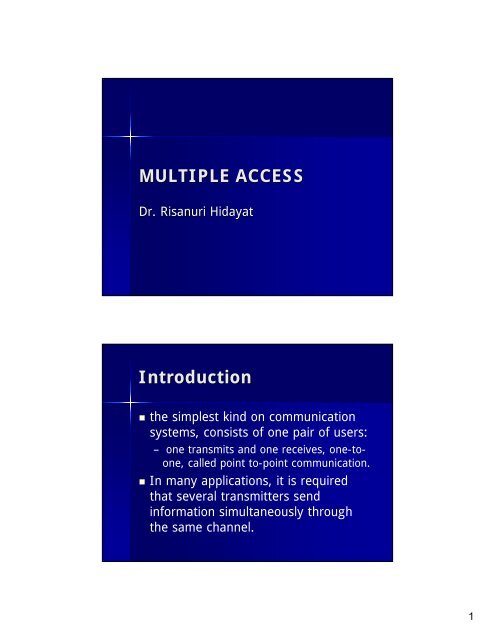
<strong>MULTIPLE</strong> <strong>ACCESS</strong><br />
Dr. Risanuri Hidayat<br />
<strong>Introduction</strong><br />
• the simplest kind on communication<br />
systems, consists of one pair of users:<br />
– one transmits and one receives, one-toone,<br />
called point to-point communication.<br />
• In many applications, it is required<br />
that several transmitters send<br />
information simultaneously through<br />
the same channel.<br />
1
<strong>Introduction</strong><br />
• As an example:<br />
– a cellular telephone system. A base<br />
station is placed in the center of each cell<br />
to provide the communication services of<br />
all mobile phone users over the area<br />
covered by the radio waves.<br />
– several mobile phone users may need to<br />
communicate with the same base station<br />
at the same time.<br />
<strong>Introduction</strong><br />
• other examples of multiple access<br />
communications:<br />
– ground stations communicating with a<br />
satellite,<br />
– local-area network,<br />
– packet-radio network,<br />
– cable televisionnetwork,<br />
–etc<br />
2
<strong>Introduction</strong><br />
• Problem: interference each other.<br />
• For example,<br />
– in wired telephone systems, it causes crosstalk<br />
between different telephone links. In cellular<br />
telephony systems, it causes<br />
– serious interference between users, if the same<br />
radio frequency is used simultaneously by<br />
distinct users.<br />
<strong>Introduction</strong><br />
• scenario of multiple access<br />
3
Frequency-division Multiple Access (FDMA)<br />
• Radio-frequency modulation enables several<br />
transmissions to coexist in time and space<br />
without mutual interference by using<br />
different carrier frequencies.<br />
– Currently information transmitted over most of<br />
the radio and television broadcast systems is in<br />
analogue form.<br />
– Digital broadcast systems that provide better<br />
quality of audio and video will become popular in<br />
the future.<br />
FDMA<br />
4
The spectrum<br />
Time-division Multiple Access (TDMA)<br />
• In time-division multiple access (TDMA)<br />
systems, all users use the same frequency<br />
band, but the time domain is partitioned<br />
into slots assigned to each user<br />
5
TDMA<br />
TDMA<br />
• In a TDMA system, user k can transmit data<br />
only in the time slots assigned to user k.<br />
• Therefore. each user's data are not<br />
transmitted continuously.<br />
• Under this scenario. one may ask why the<br />
voice can be transmitted and received<br />
continuously in a TDMA system without any<br />
feeling of time-sharing. This problem is<br />
solved by partitioning the continuous voice<br />
signal into small segments.<br />
6
TDMA<br />
• For example, for a four-user TDMA system, assume that each<br />
• slot occupies 1 ms. Then each user can use one slot every<br />
4ms.<br />
• The voice signal is then each user can use one slot every 4ms.<br />
The voice signal is then partitioned into segments of 4 ms<br />
each. Each segment is then converted (and compressed) into<br />
digital form.<br />
• Assume that a total of B bits of voice data is produced for<br />
each segment of voice signal. The transmitter then transmits<br />
the B bits during each allowed 1 ms slot,<br />
• The receiver receives each user's data at the corresponding<br />
time slot and reconstructs the voice signal in the following 4<br />
m:. All reconstructed voice segments are concatenated in<br />
time, resulting in a continuous voice signal.<br />
TDMA<br />
7
TDMA<br />
TDMA<br />
• Note that the bit rate as we, as the<br />
bandwidth of a communication system<br />
will be increased if the TDMA system<br />
is used.<br />
8
Examples of TDMA and<br />
FDMA System<br />
• systems that use these both FDMA and<br />
TDMA technologies<br />
– GSM Mobile Phone System (Both FDMA and<br />
TDMA)<br />
– T1 to T4 Systems (TDMA)<br />
– Digital Enhanced Cordless Telecommunication<br />
(DECT) (FDMA and TDMA)<br />
– Digital Audio Broadcasting (DAB) (FDMA and<br />
TDMA)<br />
GSM Multiple Access<br />
• For the GSM system, RF are in the range of 900,<br />
1800 and 1900MHz.<br />
– Each RF channel consists of‘124 sub channels and each<br />
subchannel has a bandwidth 0.2 MHz with eight TDMA<br />
systems.<br />
– Thus, each GSM has a bandwidth around 124 x0.2 ≈25<br />
MHz.<br />
– Each carrier frequency is shared by eight users in the<br />
TDMA fashion.<br />
– The total number of users is 124 x 8 ≈ 1000.<br />
– So, the GSM system allows maximum 1000 users to access<br />
one base station.<br />
– The GSM system uses Gaussian Minimal-shift Keying<br />
(GMSK), that is quite similar to the FSK technique for<br />
digital modulation.<br />
9
T1 –T4 Multiple Access<br />
• The T1 to T4 systems are transmission lines along<br />
which data are transmitted by, using the base-band<br />
pulse transmission method. There is no carrier<br />
frequency involved, so these systems all use the<br />
TDMA technique.<br />
– bit rate for T1 is 1.544Mbps with 24 channels, and each<br />
channel transmits data with 64Kbps.<br />
– The T2 system has 6.312Mbps and is equal to four T1s,<br />
and thus 96 channels.<br />
– The T3 system has 44.13 Mbps and is equivalent to seven<br />
T2s and has 672 channels.<br />
– Finally, T4 has 274.17 Mbps, is equal to six T3s, and has<br />
4032 channels.<br />
DECT<br />
• In the home we often use cordless phones. Thus,<br />
some wireless communication technique must be<br />
used. Our present cordless phone system actually<br />
allows people in the house to talk to each other.<br />
– The channel spacing of DECT is 1.728 MHz located in the<br />
1880-1900 MHz.<br />
– DECT employs the TDMA technology with 24-timeslot per<br />
carrier frequency.<br />
– Thus, a single DECT carrier can support multiple calls over<br />
a single RF transceiver. The modulation technique<br />
employed in the DECT is the Gaussian Frequency-shift<br />
Keying (GFSK) which is also a special form of the FSK<br />
10
Code-division Multiple Access (CDMA)<br />
• In the code-division muLtiple access<br />
(CDMA) method, each user is given a<br />
unique code to represent ls and 0s.<br />
• All of the signals thus overlap both in<br />
time and in frequency.<br />
• The basic requirement is that the<br />
codes are orthogonal<br />
Two-user CDMA System<br />
User 1<br />
User 2<br />
11
Two-user CDMA<br />
User 1<br />
User 2<br />
Two-user CDMA<br />
• s1(t) and s2(t) also overlap in the frequency<br />
domain<br />
• Signals s1(t) and s2(t) are mutually ortho7onal over<br />
(0,T)<br />
12
Two-user CDMA<br />
• Figure below show examples of s1(t) and<br />
s2(t) witb the message sequence<br />
– 1010 1101 for user 1 and<br />
– 0110 1011 for user 2,<br />
• where the signaling interval T is assumed to<br />
• be one second. Assume that both<br />
transmitted signals are received peridically.<br />
Two-user CDMA<br />
13
Two-user CDMA<br />
CDMA model of 2 users<br />
14
K-users CDMA<br />
• For a general K-user CDMA system, each<br />
user is assigned a particular signature<br />
waveform which corresponds to a sequence<br />
of +1 and -1 of length N.<br />
• Let s k : (s k0 ,s k1 ,...,s k(N-1) ) be the sequence of<br />
user k, where each s kj equals +1 or -1 for<br />
j=0, 1,...,N-1.<br />
K-users CDMA<br />
• where Tc= T/N<br />
• p(t) is a rectangular signal within (0, Tc)<br />
– p(t)=1 for 0
K-users CDMA<br />
• For example, a sequence<br />
(+1,+1,-1,+1,-1, -1,+1,-1)<br />
• of length 8 corresponds to the signature signal<br />
shown in Figure 6-11.<br />
• It can be proved that the bandwidth of a CDMA<br />
signal has a broader spectrum than that of the<br />
original base-band signal.<br />
• Therefore, the transmitted signal is expanded in the<br />
spectrum, and consequently a CDMA system is also<br />
called a spread spectrum system.<br />
K-users CDMA<br />
16
K-users CDMA<br />
• Let there be K users.<br />
– In the CDMA system, user k uses his own code<br />
sequence s k (t) to represent binary symbol I.<br />
User k sends m k s k (t) where m k = ±1.<br />
–If I(0) is sent, m k = 1(-1), we require that the K<br />
sequences be mutually orthogonal.<br />
– These K sequences are mixed together to be<br />
send as the message signal.<br />
• Thus the send signal is,<br />
K-users CDMA<br />
• Since the s k (t) are orthogonaL, m k can be<br />
easily detected by performing an inter<br />
product of s(t) and s k (t). It can be easily<br />
seen that<br />
• If the inner product is positive, then m k =+1,<br />
otherwise m k =-1<br />
17
Hadamard Matrices<br />
• The problem now is how to find a set<br />
of k orthogonal signature waveforms<br />
so that for<br />
k != k’<br />
Hadamard Matrices<br />
• From the equation, the inner product of<br />
sk(t) and sk’(t) is zero if and only if the<br />
inner product of the two vectors sk and sk’<br />
is zero.<br />
• For example.<br />
– in the two-user system.<br />
– s1 = (+1, +1) and s2 = (+1, -1).<br />
• It is obvious that the inner product of s1<br />
and s2 is zero and therefore<br />
=0.<br />
18
Hadamard Matrices<br />
• For a set of N-dimensional signature<br />
sequences (vectors), there are at most<br />
N orthogonal vectors.<br />
• We may generate a set of orthogonal<br />
vectors by Walsh functions.<br />
• Walsh functions are generated by<br />
special square matrices called<br />
Hadamard-matrices<br />
Hadamard Matrices<br />
19
Hadamard Matrices<br />
• It can be shown that the inner product<br />
of different rows from H 2m equals zero.<br />
• Therefore, the signature sequence sk<br />
for user k can be assigned as the k th<br />
row of H N with N = K = 2 m .<br />
• This method guarantees that two<br />
arbitrary different signature signals are<br />
orthogonal.<br />
Hadamard Matrices<br />
20
Hadamard Matrices<br />
Hadamard Matrices<br />
• Each user will use one of the rows. That is,<br />
– when user k sends 1, it sends sk, the the k th row<br />
of H8.<br />
– when user k sends 0, it sends -sk,<br />
• For instance,<br />
– user 2 will send<br />
S2= [+1 -1 +1 -1 +1 -1 +1 -1] if he intends to<br />
send 1<br />
– user 3 will send<br />
S3 =[-1 -1 +1 +1 -1 -1 +1 +1] if he intends to<br />
send 0.<br />
21
Hadamard Matrices<br />
• Consider the case where users 1,2 and 3<br />
send 1, 0 and 0 respectively.<br />
• That is,<br />
– m1= +1, m2= -1 and m3= -1.<br />
• The following signals will be sent:<br />
Hadamard Matrices<br />
• The received signal will be<br />
• the inner product to recover y1, y2 and y3,<br />
we compute<br />
z.s1, z.s2 and z.s3 as<br />
22
Hadamard Matrices<br />
Since x1> 0, then m1 = +1<br />
Since x2< 0, then m2 = -1<br />
Hadamard Matrices<br />
Since x3< 0, then m3 = -1<br />
23
Advantages of CDMA<br />
• The bandwidth of the CDMA is larger because each symbol<br />
consists of a number of bits and each bit must be of smaller<br />
pulse length. And a small pulse length will give us a larger<br />
bandwidth.<br />
• What is the advantage of having a larger bandwidth?<br />
• Note that the signal, after it leaves the transmitter, may go<br />
into different directions and reflections may occur. Thus, one<br />
signal becomes several signals and they will all reach the<br />
receiver. This problem is called the multipath problem.<br />
• A larger bandwidth will make us easier to overcome this<br />
difficulty. The CDMA technology is used in the thirdgeneration<br />
mobile systerns because, when we use a mobile<br />
phone, we may be moving and the multipath problem can be<br />
a serious one.<br />
• In such an environment, CDMA is of course quite desirable.<br />
Carrier-sense Multiple Access (CSMA)<br />
• Carrier-sense multiple access (CSMA) is widely used<br />
in a local-area network (LAN) where several host<br />
computers are connected. All of the computers will<br />
talk to one another.<br />
24
Carrier-sense Multiple Access (CSMA)<br />
• Ethernet employs a bus. Naturally, only one<br />
user can have access to it.<br />
• It is important to note that Ethernet is a<br />
computer network.<br />
• Information flowing through it is data, not<br />
say voice. Thus there is no requirement that<br />
the information has to be received by<br />
someone in real time.<br />
Carrier-sense Multiple Access (CSMA)<br />
• Let us assume that there is only one computer, say computer<br />
A, which is sending data to computer B.<br />
• Data are in digital form and prepared into frames, or packets.<br />
Each frame will contain some control information.<br />
• For instance, we have to let the network know who is sending<br />
the frame, who is proposed to receive the frame and so on.<br />
• As the frame propagates from computer A to the Ethernet<br />
bus, it fully occupies the bus. Thus all computers connected to<br />
the bus can receive the framre.<br />
• Since the control information of the frame tells us that<br />
computer B is to receives the frame. all other computers<br />
ignore it and only computer B receive it.<br />
25
Carrier-sense Multiple Access (CSMA)<br />
• Since the Ethernet allows a sender to fully<br />
occupy it, each computer must check<br />
whether anyone is occupying the bus.<br />
• The computer has to have the ability to<br />
sense whether there is any signal<br />
transmitted over the bus.<br />
• This is why this kind of checking whether<br />
there is a signal occupying the bus is called<br />
'carrier sense'.<br />
CSMA/CD<br />
• Since a bus allows only one user to occupy it, when two<br />
computers simultaneously send signals to the bus, collision<br />
occurs and this must be resolved. The Ethernet enables each<br />
sender to be able to monitor whether a collision occurs or not.<br />
• If a sender senses a collision, it backs off immediately. That<br />
is, it stops sending signals to the bus. It does not send the<br />
signal back right away. Instead, it waits for a certain period of<br />
time and transmits again.<br />
• A random number generator determines the length of this<br />
period of time.<br />
• Thus, if two senders simultaneously back off, the probability<br />
that they will send signals back at the same time is very<br />
small.<br />
• This kind of CSMA system is called carrier-sense multiple<br />
access with collision detection (CSMA/CD).<br />
26
CSMA/CA<br />
• Another way of solving the collision problem in a CSMA<br />
system is to avoid collisions at the very beginning.<br />
• The system requires each user to send an exceedingly short<br />
message signal to the bus to reserve the system. If a collision<br />
of this reservation occurs, it is solved by the method<br />
discussed in the above paragraph.<br />
• Because these reservation messages are very short, the<br />
overhead caused by resolving their collision is quite slight.<br />
• After a sender successfully reserves the bus, it can send<br />
signals and only it can send signals.<br />
• This kind of system is called a carrier-sense multiple-access<br />
with collision avoidance (CSMA/CA).<br />
• IEEE 802.11a WLAN system uses this technology.<br />
27